Stateful Failover for IP Security (IPsec) allows a router to continue processing and forwarding IPsec packets after a planned or unplanned outage occurs. A backup (secondary) router automatically takes over the tasks of the active (primary) router if the active router loses connectivity for any reason. This process is transparent to the user and requires neither adjustment nor reconfiguration of any remote peer.
IPsec Overview
IPsec is a framework of open standards that provides data confidentiality, data integrity, and data authentication among participating peers. It provides these security services at the IP layer; it uses Internetwork Key Exchange (IKE) to handle negotiation of protocols and algorithms based on local policy, and to generate the encryption and authentication keys to be used by IPsec. You can use IPsec to protect one or more data flows between a pair of hosts, between a pair of security gateways, or between a security gateway and a host.
Stateful Failover for IPsec
Stateful Failover for IPsec is designed to work in conjunction with Stateful Switchover (SSO) and Hot Standby Router Protocol (HSRP).
HSRP provides network redundancy for IP networks, helping ensure that user traffic immediately and transparently recovers from failures in network edge devices or access circuits. That is, HSRP monitors both the inside and outside interfaces so that if either interface goes down, the whole router is deemed to be down and ownership of IKE and IPsec security associations is passed to the standby router (which transitions to the HSRP active state).
SSO allows the active and standby routers to share IKE and IPsec state information so that each router has enough information to become the active router at any time. To configure Stateful Failover for IPsec, a network administrator should enable HSRP, assign a virtual IP address, and enable the SSO protocol.
Enabling HSRP: IP Redundancy and a Virtual IP Address
HSRP provides two services-IP redundancy and a virtual IP (VIP) address. Each HSRP group can provide either or both of these services. IPsec Stateful Failover uses the IP redundancy services from only one HSRP standby group. It can use the VIP address from one or more HSRP groups. Use the following guidelines to configure HSRP on the outside and inside interfaces of the router.
• Both the inside (private) and outside (public) interfaces must belong to separate HSRP groups, but the HSRP group number can be the same.
• The state of the inside and outside interfaces must be the same-both interfaces must be in the active state or standby state; otherwise, the packets will not have a route out of the private network.
• Standby priorities should be equal on both active and standby routers. If the priorities are not equal, the higher-priority router will unnecessarily take over as the active router, negatively affecting uptime.
• The interface access control list (ACL) should allow HSRP traffic to flow through.
Each time an active device relinquishes control to become the standby device, the active device reloads. This function helps ensure that the state of the new standby device synchronizes correctly with the new active device.
SSO: Interacting with IPsec and IKE
SSO is a method of providing redundancy and synchronization for many Cisco IOS® Software applications and features. SSO is necessary for IPsec and IKE to learn about the redundancy state of the network and to synchronize its internal application state with its redundant peers.
Prerequisites: The HSRP should be configured before enabling SSO.
Prerequisites and Restrictions for Stateful Failover for IPsec
This document assumes that you have a complete IKE and IPsec configuration.
The IKE and IPsec configuration that is set up on the active device must be duplicated on the standby device. In other words, the cryptographic configuration must be identical with respect to Internet Security Association and Key Management Protocol (ISAKMP) policy, ISAKMP keys (preshared), IPsec profiles, IPsec transform sets, all cryptographic map sets that are used for Stateful Failover, and all ACLs that are used in match address statements on the cryptographic map sets.
• Both the active and standby devices must run the identical version of the Cisco IOS Software, and both the active and standby devices must be connected through a hub or switch.
• HSRP requires the inside interface to be connected through LANs.
Device Requirements
• The active and standby Cisco IOS Software routers must be running the same Cisco IOS Software release, Release 12.3(11) T or later.
• Stateful Failover for IPsec requires that your network contain two identical routers that are available to be either the primary or secondary device. Both routers should be the same type of device, have the same CPU and memory, and have either no encryption accelerator or identical encryption accelerators.
Supported Deployment Scenarios: Stateful Failover for IPsec
It is recommended that you implement IPsec Stateful Failover in one of the following deployment scenarios:
• Single-interface scenario
• Dual-interface scenario
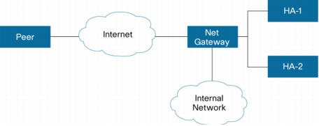
Single Interface
In a single-interface scenario, the VPN gateways use one LAN connection for both encrypted traffic arriving from remote peers and decrypted traffic flowing to inside hosts (Figure 1).
The single-interface design allows customers to save money on router ports and subnets. This design is typically used if all traffic flowing in and out of the organization does not traverse the VPN routers.
The role of HSRP is simplified in a single-interface design because if the only interface is disabled, the entire device is deemed unavailable.
Figure 1. Single-Interface Network Topology
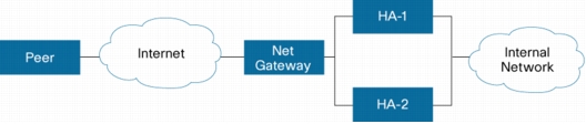
Dual Interfaces
In a dual-interface scenario, a VPN gateway has more than one interface, enabling traffic to flow in and out of the router through separate interfaces (Figure 2).
This scenario is typically used if traffic flowing in and out of a site must traverse the routers, so the VPN routers provide the default route out of the network.
HSRP configured for mutual tracking means that if the outside interface does fail, the inside interface on the same router will also be deemed down, allowing for complete router failover to the secondary router.
Figure 2. Dual Interface Network Topology
How to Configure Cisco Stateful Failover for IPsec
Dual-interface configuration tasks for Stateful Failover for IPsec include:
• Enabling HSRP: IP Redundancy and a Virtual IP Address
• Enabling SSO
• Enabling Stateful Failover for a IKE and IPsec
• Managing Antireplay Interval
Enabling HSRP: IP Redundancy and a Virtual IP Address
Use the following commands to enable HSRP on both interfaces of each router (Table 1):
1. enable
2. configure terminal
3. interface type number
4. standby standby-group-number name standby-group-name
Configures an interface type for the router and enters interface configuration mode
Step 4
standby standby-group-number name standby-group-name
Example:
Router(config-if)# standby 1 name HA-out
Assigns a user-defined group name to the HSRP redundancy group
Note: The standby-group-number argument should be the same for both routers that are on directly connected interfaces. However, the standby-group-name argument should be different between two (or more) groups on the same router.
The standby-group-number argument can be the same on the other pair of interfaces as well.
Step 5
standby standby-group-number ip ip-address
Example:
Router(config-if)# standby 1 ip 209.165.201.1
Assigns an IP address that is to be "shared" among the members of the HSRP group and owned by the primary IP address
Note: The virtual IP address must be configured identically on both routers (active and standby) that are on directly connected interfaces.
Step 6
standby standby-group-number track interface-name
Example:
Router(config-if)# standby 1 track Ethernet1/0
Configures HSRP to monitor the second interface so that if either of the two interfaces goes down, HSRP causes failover to the standby device
Note: Although this command is not required, it is recommended for dual-interface configurations.
Step 7
standby [group-number] preempt
Example:
Router(config-if)# standby 1 preempt
Enables the active device to relinquish control because of an interface tracking event
(Optional) Configures the time between hello packets and the time before other routers declare the active hot standby or standby router to be down
• holdtime: Holdtime is the amount of time the routers take to detect types of failure. A larger hold time means that failure detection will take longer.
For the best stability, it is recommended that you set the hold time between 5 and 10 times the hello interval time; otherwise, a failover could falsely occur when no actual failure has happened.
Configures the delay period before the initialization of HSRP groups
Note: It is suggested that you enter 120 as the value for the reload-delay argument and leave the min-delay argument at the preconfigured default value.
Examples
The following example shows how to configure HSRP on a router:
interface Ethernet0/0
ip address 209.165.201.1 255.255.255.224
standby 1 ip 209.165.201.3
standby 1 preempt
standby 1 name HA-out
standby 1 track Ethernet1/0
standby delay minimum 120 reload 120
After you have successfully configured HSRP on both the inside and outside interfaces, you should enable SSO as described in the following section.
Enabling SSO
Use the following commands to enable SSO, which is used to transfer IKE and IPsec state information between two routers (Table 2):
Defines the redundancy scheme that is to be used; currently, "standby" is the only supported scheme
• standby-group-name: Must match the standby name specified in the standby name interface configuration command. Also, the standby name should be the same on both routers.
Note: Only the active or standby state of the standby group is used for SSO. The VIP address of the standby group is neither required nor used by SSO.
Step 5
exit
Example:
Router(config-red-interdevice)# exit
Exits interdevice configuration mode
Step 6
ipc zone default
Example:
Router(config)# ipc zone default
Configures the interdevice communication protocol, Inter-Process Communication (IPC), and enters IPC zone configuration mode
Use this command to initiate the communication link between the active router and standby router.
Step 7
association 1
Example:
Router(config-ipczone)# association 1
Configures an association between the two devices and enters IPC association configuration mode.
Step 8
protocol sctp
Example:
Router(config-ipczone-assoc)# protocol sctp
Configures Stream Control Transmission Protocol (SCTP) as the transport protocol and enters SCTP protocol configuration mode
Step 9
local-port local-port-number
Example:
Router(config-ipc-protocol-sctp)# local-port 5000
Defines the local SCTP port number that is used to communicate with the redundant peer and puts you in IPC transport-SCTP local configuration mode
• local-port-number: There is not a default value. This argument must be configured for the local port to enable interdevice redundancy. Valid port values are 1 to 65535.
The local port number should be the same as the remote port number on the peer router.
Defines at least one local IP address that is used to communicate with the redundant peer
The local IP addresses must match the remote IP addresses on the peer router. There can be either one or two IP addresses, which must be in the global Virtual Routing and Forwarding (VRF) process. A virtual IP address cannot be used.
Defines the remote SCTP port number that is used to communicate with the redundant peer and puts you in IPC transport-SCTP remote configuration mode
Note: remote-port-number: There is not a default value. This argument must be configured for the remote port to enable interdevice redundancy. Valid port values are 1 to 65535.
The remote port number should be the same as the local port number on the peer router.
Defines at least one remote IP address of the redundant peer that is used to communicate with the local device
All remote IP addresses must refer to the same device.
A virtual IP address cannot be used.
Examples
The following example shows how to enable SSO:
!
redundancy inter-device
scheme standby HA-in
!
!
ipc zone default
association 1
no shutdown
protocol sctp
local-port 5000
local-ip 10.0.0.1
retransmit-timeout 300 10000
path-retransmit 10
assoc-retransmit 10
remote-port 5000
remote-ip 10.0.0.2
!
Enabling Stateful Failover for IKE and IPsec
There is no specific command-line interface (CLI) necessary to enable Stateful Failover for IKE. It is enabled for a particular VIP address when a Stateful Failover crypto map is applied to an interface.
Use the following commands to enable Stateful Failover for IPsec (Table 3). All IPsec state information is transferred from the active router to the standby router through the SSO redundancy channel that was specified in the task "Enabling SSO":
Binds the crypto map on the specified interface to the redundancy group
Note: Although the standby group does not have to be the same group that was used when enabling SSO, it does have to be the same group that was used with the standby ip command on this interface.
This crypto map uses the same VIP address for both IKE and IPsec to communicate with peers.
Use the following commands to modify the interval in which an IP redundancy-enabled crypto map forwards antireplay updates from the active router to the standby router (Table 4):
Modifies the interval at which inbound and outbound replay counters are passed from an active device to a standby device
• inbound in-value: This value is the number of inbound packets that are processed before an antireplay update is sent from the active router to the standby router. The default value is one update every 1,000 packets.
• outbound out-value: This value is the number of outbound packets that are processed before an antireplay update is sent from the active router to the standby router. The default value is one update every 100,000 packets.
Step 4
exit
Example:
Router (config)# exit
Exits global configuration mode
Configuration Examples for Stateful Failover
This section includes configuration of the active and standby routers.