This document provides a sample configuration for Cisco® Enhanced Easy VPN Remote connecting to a primary Easy VPN server with crypto map configuration, and connecting to an enhanced Easy VPN server with dial backup when the primary VPN server fails. This enhanced Easy VPN configuration uses Dynamic Virtual Tunnel Interface (DVTI).
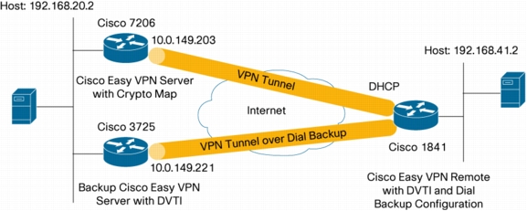
Figure 1.Network Diagram
CISCO ENHANCED EASY VPN WITH DVTI
Cisco Enhanced Easy VPN is a new method for configuring Easy VPN using DVTIs. It can be used on both the Easy VPN Server and Easy VPN Remote routers. It relies on Virtual Tunnel Interface (VTI) to create a virtual access interface for every new Easy VPN tunnel. The configuration of the virtual access interface is cloned from a virtual template configuration. The cloned configuration includes the IP Security (IPSec) configuration and any Cisco IOS® Software feature configured on the virtual template interface, such as quality of service (QoS), NetFlow, or access control lists (ACLs).
With Cisco Enhanced Easy VPN, users can provide highly secure connectivity for remote-access VPNs. Enhanced Easy VPN can be combined with Cisco AVVID (Architecture for Voice, Video and Integrated Data) to deliver converged voice, video, and data over IP networks.
BENEFITS
• Simplifies Management-Customers can use the Cisco IOS virtual template to clone, on demand, new virtual access interfaces for IPSec. This simplifies VPN configuration complexity, which translates into reduced costs. In addition, existing management applications now can monitor separate interfaces for different sites.
• Provides a Routable Interface-Cisco IOS IPSec DVTIs support all types of IP routing protocols. Customers can use these capabilities to connect larger office environments, such as branch offices.
• Improves Scaling-IPSec DVTIs use single security associations per site to cover different types of traffic, thus enabling improved scaling.
• Offers Flexibility in Defining Features-An IPSec DVTI is an encapsulation within its own interface. This offers flexibility of defining features for clear-text traffic on IPSec VTIs, and features for encrypted traffic on physical interfaces.
CONFIGURATION SUMMARY
This spoke router uses reliable static routing to discover when the primary Cisco Easy VPN Server fails. Reliable static routing uses the IP SLA monitor feature to monitor a remote destination. The reliable static routing does polling of the Easy VPN server availability every 10 seconds. When connectivity to the primary server fails, the reliable static routes are removed from the routing table and Easy VPN replaces the active crypto map with the backup crypto map. This enables a floating static route to become active and initiate a crypto session over the backup path. The floating static route causes the traffic to be encrypted by the backup path and to be forwarded out the dialup interface.
During the primary network path failure, the IP SLA monitor continues to monitor the primary server availability. When the IP SLA monitor detects that the primary Easy VPN Server is reachable, it will reinstall the reliable static route in the routing table, replacing the floating static route, and will reactivate the primary crypto map. While traffic is being forwarded to the primary server, the backup path becomes idle, causing the dialup to time out and bring down the backup interface.
The traffic is forwarded to or from the IPSec tunnel interface by virtue of the IP routing table lookup. Routes are dynamically learned during Internet Key Exchange (IKE) Mode configuration exchange and inserted into the routing table pointing to the virtual access interface.
This configuration allows for split tunneling. With split tunneling, remote users can send traffic destined to the Internet directly without going onto the IPSec tunnel.
The remote router is using dynamic IP addresses, a typical configuration for DSL and cable connectivity. The remote router is also using Network Extension Mode. In this mode, the remote subnet is visible to the hub network. This enables the support of devices such as voice over IP (VoIP) phones located at the remote site. This configuration can be used for User Mode as well.
This configuration shows two types of Easy VPN tunnels: a traditional Easy VPN tunnel using the primary path and an Enhanced Easy VPN tunnel with DVTI using the backup path. The two different types of tunnels were used for the purpose of demonstration only; both tunnels can be of the same type. With a traditional Easy VPN tunnel, one or more IPSec security associations are created for each IPSec tunnel (depending on the server configuration); each IPSec security association allows a specific source and destination IP address on the IPSec tunnel. With Enhanced Easy VPN, only one IPSec security association is created for each IPSec tunnel with any source to any destination IP addresses.
For more information about the IPSec DVTI feature, see "IPSec Virtual Tunnel Interface" (a link is provided in the Related Information section of this document).
LIMITATIONS
This guide provides a sample of Easy VPN configuration with DVTI configuration only.
• This guide does not cover a full security audit on the router. It is recommended that users run a Cisco Router and Security Device Manager (SDM) security audit in Wizard Mode to secure the router.
• An initial router configuration step is not shown in the steps. The full configuration is shown in the following section.
• This configuration guide enables split tunneling. Split tunneling is enabled on the hub by the ACL command under the crypto isakmp client configuration mode. To disable the split tunneling on the remote, remove the ACL command from the Easy VPN Server.
• The spoke is configured with Port Address Translation (PAT) to provide connectivity over the Internet. The spoke configuration requires Cisco IOS Software Release 12.4(4)T to work.
• This configuration uses Network Extension Mode. For details on configuring User Mode, please review documentation for Cisco Easy VPN Remote or Server.
• This configuration does not include multicast.
COMPONENTS USED
The sample configuration uses the following releases of the software and hardware:
• Cisco IOS Software Release 12.4(4)T
• Cisco 1841, 3725, and 7206 routers
Figure 1 illustrates a sample network configuration.
The information presented in this document was created from devices in a specific lab environment. All of the devices started with a cleared (default) configuration. If you are working in a live network, it is imperative to understand the potential impact of any command before implementing it.