Cisco IOS IP Service Level Agreement (SLA) is a feature embedded in Cisco IOS Software. It allows Cisco customers to understand IP service levels, increase productivity, lower operational costs, and reduce the frequency of network outages. The Cisco IOS IP SLA feature performs active monitoring of network performance and can be used for network troubleshooting, network readiness assessment and health monitoring.
Enterprise video is rapidly becoming the dominant consumer of network bandwidth, as well as a major factor in network design. With the advent of telepresence, video conferencing, and video calls, it is extremely important to ensure there is sufficient reliability and network capacity for sustaining these applications. The growing trend is that video traffic will exceed 50 percent of the network capacity. This can be attributed to the larger video bandwidth requirements relative to previous data streams.
Enterprise video represents different challenges for networks in pre-deployment assessment, service monitoring, as well as troubleshooting. IP Service Level Agreement Video Operation (IPSLA VO) provides new functionality to the Cisco IPSLA feature set allowing routers and switches to stress the network in the same way as actual video applications. IPSLA VO can be used to expose the weaknesses in a network and raises alerts based on pre-defined thresholds. Once the network stress points are exposed, next steps could possibly be to deploy Quality of Service (QoS), add additional bandwidth or reset user expectations.
Prior to IPSLA VO the most common method to help test video was to use IPSLA UDP probes, since video traffic streams are UDP-based. The main drawback to using this approach is that platform independent software features, such as IPSLA, have inherent limitations in generating the high data rates (4 Mbps - 16 Mbps) which are typical of video applications. IPSLA VO probes are designed to stress the network, whereas previous IP SLA probes were designed for measurements within the existing network infrastructure. The existing UDP-based IPSLA probes rely on an operating system timer which is insufficient for the packet generation requirements for a true video stream. IPSLA VO as described in this document addresses this limitation, by relying on platform specific timers that will enable a more precise timer interrupt, as well as the ability to generate high data rates. Using platform dependent timers eliminates protocol overhead and process scheduling delays that can contribute to the limitations of the current software to generate high rates of video traffic.
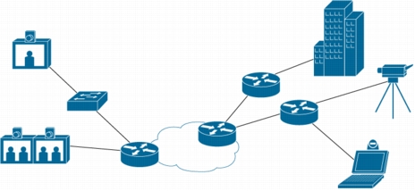
Figure 1. Typical Video Network
A typical video network can incorporate many different types of video endpoints representing different characteristics. IPSLA VO is available initially on the Cisco Catalyst 3K platforms beginning with Cisco IOS Software Release 12.2(58)SE and is packaged with profiles representing IPTV (unicast), Cisco IP Cameras for video surveillance and Cisco telepresence. IPSLA VO also supports the addition of custom profiles that the operator can upload to the router.
Best Practices
IPSLA VO incorporates the best practices found in many existing IPSLA designs and adds some additional recommendations due to the new functionality and potentially high data rates.
• IPSLA Responder
The responder functionality will increase the IPSLA RTT accuracy by subtracting the processing delay of the devices. IPSLA VO requires an IPSLA responder, whereas this functionality is optional on some other IPSLA probes.
• Location of IPSLA Devices
The judicious location of the IPSLA sender and responders within a network will greatly increase the IPSLA's ability to scale. A full mesh of probes will increase exponentially the amount of probes needed to cover an entire network and can easily overwhelm the available resources of a device. If possible, place the devices closest to the point of measurement.
• Multi-Operation Scheduler
This will allow the device to stagger the starting of various operations in order to smooth out the consumption of CPU resources.
• Network Time Protocol (NTP)
NTP configuration and synchronization between devices is required in order to have meaningful statistics for IPSLA VO. It is highly recommended for other IPSLA operations as well.
• Duration
IPSLA updates the statistics at the end of each operation. It is highly recommended that due to the network stress involved with IPSLA VO that test durations should be no more than 60 seconds.
IP SLA Video Packet flow
IPSLA is comprised of two main components, the IPSLA sender and the IPSLA responder. The sender is responsible for the generation, receipt and analysis of the traffic to target devices. The responder is responsible for adding timestamps and increasing the accuracy of the sender traffic.
IPSLA VO uses the existing IPSLA control channel (by default over UDP port 1967) but adds some additional functions that are unique as well.
The IPSLA sender will initiate an operation based upon the configuration of the device and sends a control message to the IPSLA responder with the specified port number and duration of the operation. If the IPSLA sender receives an "OK" reply from the responder it will begin sending test packets.
With IPSLA VO, IPSLA passes control of the test packets to the platform component. The platform components are responsible for the generation of the test packets on the sender and the responder "test sink".
When the responder "test sink" receives a signal that no more test packets will arrive from the sender, the test sink is turned off and a message is sent from the responder containing the statistics that was gathered by the responder. This sender reads this message and updates all relevant fields. IP SLA updates the counters at the end of an operation. If an operation is configured for a long period of time, there will not be any information until it is completed.
Note that all video operations are one-way and require the responder to collect and verify packets sent from the IPSLA sender. The sender gets the computed statistics through the proprietary control message protocol and makes three attempts to retrieve the statistics before it times out.
CLI Configuration
IPSLA VO adds additional functionality to the existing IPSLA feature set. This additional functionality is reflected in additional keywords and parameters in the configuration. The CLI will be familiar to anyone with prior IPSLA experience.
IPSLA-sw(config)#ip sla 1
IPSLA-sw(config-ip-sla)#video ?
Hostname or A.B.C.D Destination IP address or hostname
IPSLA-sw(config-ip-sla)#video 10.4.3.19 ?
<1-65535> Port Number
IPSLA -sw(config-ip-sla)#video 10.4.3.19 3000 ?
source-ip Source address
A source IP address must be configured for use with IPSLA VO.
The "show ip sla statistics [operation]" command can provide information regarding any problems that IPSLA VO is encountering. A sample output and the explanations are listed below:
show ip sla statistics 1
IPSLAs Latest Operation Statistics
IPSLA operation id: 1
Type of operation:
Packets:
Latency one-way time:
Number of Latency one-way Samples: 0
Source to Destination Latency one way Min/Avg/Max: 0/0/0 milliseconds
NTP sync state: SYNC
Inter Packet Delay Variation, RFC 5481 (IPDV):
Number of SD IPDV Samples: 0
Source to Destination IPDV Min/Avg/Max: 0/0/0 milliseconds
Packet Loss Values:
Loss Source to Destination: 0
Source to Destination Loss Periods Number: 0
Source to Destination Loss Period Length Min/Max: 0/0
Source to Destination Inter Loss Period Length Min/Max: 0/0
Out Of Sequence: 0 Tail Drop: 0
Number of successes: 0
Number of failures: 0
Operation time to live: Forever
Table 1.
Latest Operation Return Code
Explanation of Control Plane Codes
OK
The video session succeeded without error, and within all specified threshold and timeout parameters. Only meaningful with NTP sync, otherwise a false positive.
No Connection
This normally means that either the destination doesn't exist (invalid IP address, or unreachable) or that the responder is not enabled on that destination device. The SLA video operation REQUIRES the responder to be both reachable and functional for the session to start.
Over threshold
In the case of video, since there are no RTT values, if any time stamp delta (receive time-send time) is greater than the provisioned threshold value. If no NTP sync, then this error code is meaningless.
Timeout
In the case of video, since there are no RTT values, if any time stamp delta (receive time-send time) is greater than the provisioned timeout value. If no NTP sync, then this error code is meaningless.
Responder failure
A video specific failure, normally caused by video session on responder timing out, and clearing out all saved data before the sender transmits the Stat Retrieval message, which will then be rejected because no active session remains that matches the request.
Responder session timer is equal to the duration plus 15 seconds (3x retries of the Stat Retrieval control message).
Authentication failure
This is caused by failure of the key-chain MD5 authentication protocol. Either the sender or responder is missing the correct key-chain from the other device. This is a common error for all SLA operations, not just for video.
Format failure
Control message incompatibility between sender and responder. For video, means destination device does not support video.
Busy
The sender is unable to start a new video session due to bandwidth limitations. Each device can only support a certain number of video sessions, depending on the platform, and bandwidth of the selected profile.
Port in use
For video, this means that the responder is out of available resources for another video session. This is similar to the error Busy, but a different code to distinguish it from the sender bandwidth issue.
IPSLA can be configured to raise traps and syslog messages based on a configured threshold value and error conditions. These thresholds are not specific to IPSLA VO, and may be available on the other IPSLA probe types. The various reactions that can be configured are:
iaJitterSD Inter Arrival Jitter from Source to Destination
packetLossSD Packet Loss in the direction from Source to Destination
rtt Round Trip Time
timeout Timeout
Debug Commands
IPSLA supports debug commands for the sender and responder, and can provide additional detail as to the IPSLA operation. This information may be needed if the Technical Assistance Center (TAC) is engaged. Please keep in mind that debug commands will require additional CPU resources and should be used sparingly.
Sender:
debug ip sla trace
debug ip sla error
Responder:
debug ip sla trace 0
debug ip sla error 0
IPSLA Video Operation SNMP
IPSLA VO has full SNMP support using the CISCO-IP-SLA-VIDEO-MIB.my.