With the introduction of Over the ToP (OTP), Cisco has empowered enterprise customers to regain control of their WAN deployments. By focusing on simplicity, OTP helps remove the complexity of the deployment of branch networks utilizing Multiprotocol Label Switching (MPLS) Virtual Private Network (VPN), and adds the ability to utilize lower cost public networks.
Traditional MPLS VPN support deployments consist of a set of sites interconnected by an MPLS provider core network. At each customer site, one or more Customer Edge (CE) devices attach to one or more Provider Edge (PE) devices. MPLS VPN support for Enhanced Interior Gateway Routing Protocol (EIGRP) requires service providers to configure the EIGRP between PE and CE to those customers that require native support for EIGRP. Yet PE/CE deployments offer a number of challenges for enterprise customers, specifically, the following:
• Either EIGRP or Border Gateway Protocol (BGP) must be run between the PE/CE
• Service providers must enterprise routes via Multiprotocol internal BGP (MP-iBGP)
• Provider often limits the number of routes being redistributed
• Route flaps within sites and results in BGP convergence events
• Route metric changes result in new extended communities flooded into the core
In addition, the need for the service provider to carry site specific routes mean the CE devices must be co-supported, and the enterprise customer must consider the following:
• Managed services is required, even if not needed
• Control of traffic flow using multiple providers can be problematic
• Changing providers requires coordination of switch over to prevent route loops
OTP simplifies this. With OTP, enterprise customers can view the WAN as a virtual extension of the network and transparently extend their infrastructure OVER the provider's network. The advantage of this approach includes the following:
• No special requirements on the service provider (this is a provider independent solution)
• No special requirements on the enterprise customers network
• Support for both IPv4 and IPv6
• No route redistribution or site tag management
• No limitation on the number of routes being exchanged between sites
• A single routing protocol solution (convergence is not depending on the service provider)
• Works with both traditional managed and non-managed internet connections
• Compliments an L3 any-to-any architecture (optional hair pinning of traffic)
• Support for multiple WAN connections and multiple WAN providers
• Support connections are not part of the MPLS VPN backbone (aka "backdoor" links)
Drawback of Existing Solutions
First, let's recap the challenges/drawbacks of existing options.
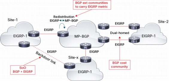
Using EIGRP on PE/CE Link:
BGP extended communities to carry EIGRP metric information across MP-BGP cloud. This allows to have internal EIGRP routes end to end, and to compare metric with the backdoor link. Here are the six defined types:
• 0x8801 (AS#, delay)
• 0x8802 (Reliability, Hop #, BW)
• 0x8803 (Load, MTU)
• 0x8804 (Remote AS#, Origin RID)
• 0x8805 (External Protocol, External metric)
• 0x8800 (Route Type, Tag)
BGP cost extended community is used to support a multi-homed site. The cost community has the format stated below:
Cost:POI:ID:value
Cost
Extended Community type, set to 0x4301
Point of Insertion (POI)
Defines at which step in BGP path selection process this attribute is used. Set to 128 for the absolute POI (pre-bestpath)
ID
128 (Internal) or 129 (external)
Value
EIGRP composite metric
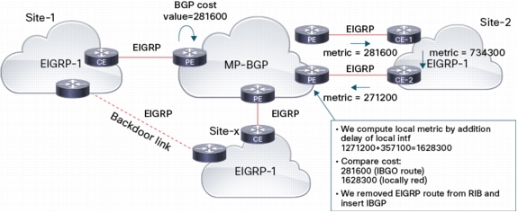
The goal is to prefer the iBGP route from originating PE, over the locally redistributed EIGRP route that might be learned in a multi-homed site. Cost community is inserted during EIGRP to BGP redistribution on the originating PE.
On the remote PE, it's compared with the cost community of BGP locally redistributed route from EIGRP (if any). The cost of the locally redistributed EIGRP route is higher since it is incremented while being propagated within the local site between the PEs. The iBGP route is then preferred over the EIGRP route received from 2nd PE and is installed in VRF RIB despite EIGRP getting a lower admin distance (90 < 200) than iBGP (it's done automatically, no need to tune the admin distance).
Note: This routing feedback avoidance mechanism involves only PEs (CEs and customer routers are not involved)
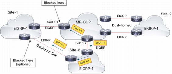
• Site of Origin (SoO)
Since DUAL has no visibility across the MPLS cloud, common parameters between BGP and EIGRP are needed to avoid routing feedback when backdoor links are present. SoO ext community already exists in BGP (used in multihomed site to avoid routing feedback of local routes) SoO support for EIGRP was added in release 12.3(8)T
The goal is to avoid injecting in MPLS/VPN routes from another site (learned through backdoor link):
• SoO marking:
Ingress PE sets SoO in BGP update:
– According to site-map attached to VRF interface if there is no SoO in EIGRP redistributed route
– Equal to SoO value already present in EIGRP redistributed route if any egress PE sets SoO in EIGRP update according to SoO value in BGP update received
• SoO checking:
– During the import process the SoO value in BGP update is checked against the SoO value of the site-map attached to VRF interface. The update is propagated to CE only if there is no match (this check is done regardless of protocol used on PE/CE link).
– At reception of EIGRP update, the SoO value in the EIGRP update is checked against the SoO value of site-map attached to the incoming interface. This update is accepted only if there is no match (this check can optionally be done on backdoor router).
Pros/Cons of the EIGRP on PE/CE Link Option:
• Allows E2E internal EIGRP routes (simplifies the backdoor link scenario)
• WAN connections are 'transparent' for end-customers (there is no other protocol involved)
– Slow convergence (BGP, import process, etc.)
– Backdoor links require SoO filtering
– Very few providers offer EIGRP PE/CE
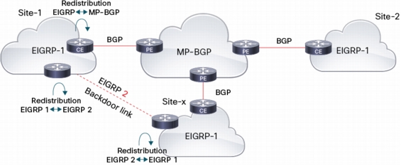
Using BGP on a PE/CE Link:
If the provider does not support EIGRP, EIGRP customers are typically left using eBGP on PE/CE. This implies that some (basic) BGP skills are needed on the customer side, or they will have to go for a managed CPE solution (where the provider takes care of the CE). BGP easily handles a dual-homed site, however some special care should be taken when there are backdoor links. Indeed, routes learned through MPLS/VPN are all external routes, and can't be compared with internal routes learned through the backdoor link. The solution is to use a separate EIGRP process on the backdoor link and utilize a mutual redistribution with the `campus' EIGRP process.
Pros/Cons of the BGP on PE/CE Link Option:
• Providers friendly (no need for redistribution on PE)
• Easy to manage dual-homed sites
• Slow convergence
• A need to use different EIGRP AS# for backdoor links
• BGP knowledge and skills needed at the customer site
EIGRP OTP Architecture
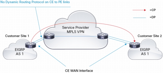
As the name implies, suppose EIGRP Over the ToP allows the customer to establish EIGRP adjacencies across the MPLS/VPN provider cloud. An EIGRP targeted adjacency between CEs is created. This EIGRP neighborship is done via unicast packets, using the CE 'WAN' IP address. This "over the top" peering allows EIGRP to exchange customer prefixes directly between CEs. Customer prefixes are NOT injected in the providers VRF routing table. In order to allow for proper forwarding of user traffic across the MPLS/VPN cloud, user packets are encapsulated on the CE. The encapsulation header uses the WAN IP address of the CEs, which are known in the MPLS/VPN cloud.
Control Plane
OTP control plane consists in an EIGRP targeted adjacency between CEs. Neighborship is established using the CE WAN address, i.e. address of CE on the PE/CE link, so there is no need for any dynamic routing protocol between the PE/CE. The PE just needs to redistribute the connected routes.
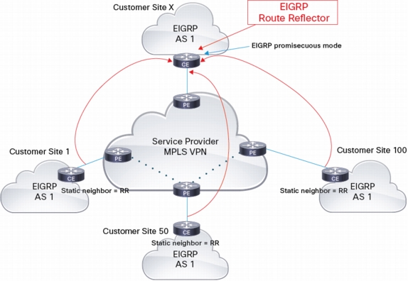
This adjacency is using unicast packets and the CE needs to know the IP of the remote CE. In the first phase of OTP, only static neighbors are allowed. With manual neighbor configuration, it wouldn't scale to establish full mesh peering between all CEs. Instead, the concept of Route Reflector, i.e. CEs peer with RRs only is used and RRs reflect the routes they receive to other CEs. Each CE is configured with the RRs WAN address and each RR is configured in EIGRP promiscuous mode, i.e. to accept incoming 'connections' (similar to BGP listen feature).
RR reflects the routes untouched, i.e. without changing the metric, and keeping next-hop unchanged
(no next-hop-self).
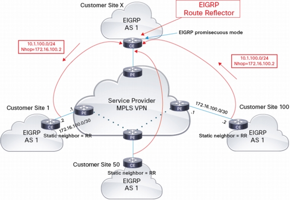
Since the next-hop is not changed (customer site 1 receives an update from the RR with next-hop = customer site 100), the RR doesn't play any role in the data plane, so it could be placed in any site. User traffic does NOT follow control plane traffic; it takes the optimum path in the MPLS/VPN cloud. Below is an entry in the routing table on the CE:
CE#show ip route
...
D 10.1.100.0/24 [90/1536640] via 172.16.100.2, 2w3d, LISP0
It points to a LISP interface (automatically created) and with next-hop learned through EIGRP.
How does OTP handle the challenges described in the Introduction?
a) Dual/multi homed sites are handled by creating a separate EIGRP session with RR (one per connection). DUAL has full visibility of all links so it handles potential routing feedback. Normal EIGRP mechanisms (see here) can be used to select primary/fallback links or to configure load balancing (even unequal cost load sharing is possible).
b) Backdoor connections: DUAL has full visibility on OTP and backdoor connections, so normal EIGRP loop prevention and metric tuning can be used to handle backdoor connections.
Data Plane
Since the customer prefixes are not known in the VRF of provider, customer traffic can't be natively forwarded through the provider cloud, but needs to be encapsulated by CEs before being sent through the provider cloud.
OTP leverages existing LISP encapsulation which:
• Allows dynamic multi-point tunneling
• Provides instance ID field to optionally support virtualization across WAN (see EVN WAN Extension section)
OTP does NOT use LISP control plane (map server/resolver, etc.) instead it uses EIGRP to exchange routes and provide the next-hop, which LISP encapsulation uses to reach remote prefixes.
For a given remote prefix:
encapsulation header source IP = local WAN address
encapsulation header dst IP = next-hop of related EIGRP route.
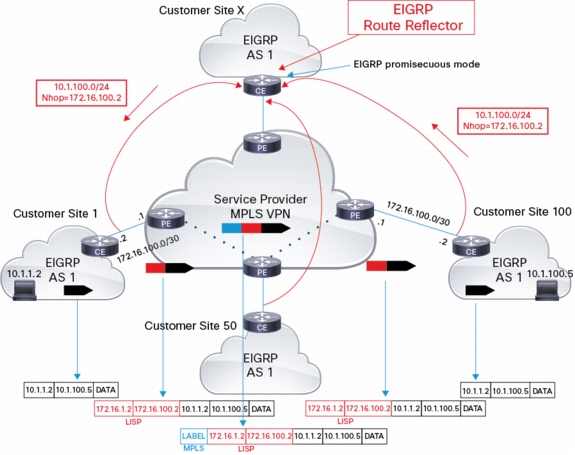
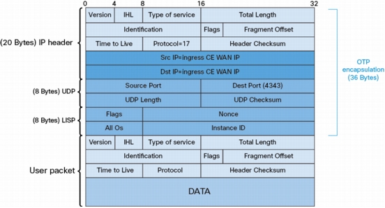
The diagram below illustrates the encapsulation details of a user packet when travelling across MPLS/VPN cloud, from left to right:
• Left CE adds LISP encapsulation with source IP set to its local WAN IP (172.16.1.2) and destination IP set to the remote CE WAN IP (172.16.100.2)
• Left PE forwards the LISP encapsulation packet by adding the MPLS label(s) used to reach the connected network of remote CE (172.16.100.0/30)
• Packet travels across MPLS cloud using optimal path to reach egress PE (i.e. the packet doesn't path through RR or top PE)
• Right PE removes MPLS label and forwards LISP encapsulated packet to right CE
• Right CE removes the LISP encapsulation and forwards packet to end user
OTP has been designed to operate within several WAN network topologies to fit the needs of different enterprise customers. Support for point-to-point peering, route reflectors to simplify large scale branch office deployment, and data encryption, allows customers to extend full network capability to mobile workers, telecommuters, and remote data centers. In the next few sections the basics related to some of the more common deployments will be covered.
OTP Peering
OTP does not provide for dynamic discovery of other peers. Instead it relies on manual configuration to specify which routers peer with which routers using the "neighbor" option under EIGRP. OTP supports two modes, point-to-point for finer control, and route-refactor for greater scaling.
Point-to-Point Peering: Point-to-point offers the simplest form of configuration within OTP, and allows OTP to form a peer with a targeted router. This option is controlled by the additional "remote" keyword on the neighbor statement. Once the configuration has been entered, EIGRP will begin sending Hello messages to the address specified. When a Hello message is likewise received from the proper address, routes will then be exchanged.
Route Reflector Peering: If the network has many sites, then OTP offers Route Reflectors (RRs) to form a half-mesh topology and ensure connectivity among all sites in the network. A Route Reflector is an EIGRP peer that receives route updates from remote sites and "reflects" the routes to other sites. Route Reflectors are configured using the keyword "unicast-listen". This option enables the Route Reflectors to listen for unicast Hello messages from other sites, and upon receiving the first Hello message, automatically forms a peering relationship. OTP supports the use of dual or multiple Route Reflectors for redundancy.
Site-to-Site traffic
While some customers may desire all traffic to pass thought the hub, it does not represent the most efficient use of bandwidth, and could lead to congestion. To improve OTP's ability to scale to 500 remote sites, OTP can be configured to preserve the next-hop address of the advertising site when routing information is sent to other sites using the "no next-hop-self" configuration under EIGRP. For more information on this command see [EIGRP Command Reference]
Site Redundancy: The add path support feature enables hubs to advertise multiple best paths to connected sites. A typical OTP deployment would consists of dual hubs (for hub redundancy) connected to more than one service provider (for service-provider redundancy) and provides up to four additional paths to connected sites. This option is configured using the "add-paths" configuration under EIGRP. If, for example there are two spokes (spoke-1 and spoke-2) at a site, and add-path is configured on the hub, both spoke-1 and spoke-2 will be advertised to other sites, thereby allowing for both redundancy (in the event of lost of connectivity to one of the spokes) and load balancing traffic to spoke-1 and spoke-2. For more information on this command see [Add Path Support in EIGRP]
OTP Over Public Internet
In addition to being able to work over traditional MPLS/VPN managed solutions, OTP has been designed with low cost public networks in mind, by offering GETVPN support. GETVPN is managed encryption without the provisioning and management nightmare, which simplifies the provisioning and management of a VPN connection. Key benefits for pairing OTP and GET VPN includes the following:
• Simplifies branch-to-branch instantaneous communications-Ensures low latency and jitter by enabling full-time, direct communications between sites, without requiring transport through a central hub.
• Maximizes security-Provides encryption for MPLS networks while maintaining network intelligence, such as full-mesh connectivity, natural routing path, and Quality of Service (QoS).
• Complies with governmental regulation and privacy laws-Helps meet security compliance and internal regulation by encrypting all WAN traffic.
• Offers management flexibility-Eliminates complex peer-to-peer key management with group encryption keys.
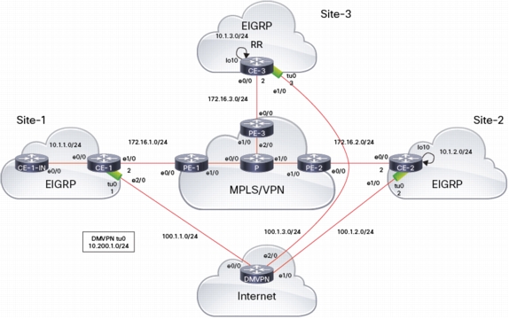
Information on how to configure OTP can be found at [EIGRP Over the Top]. To illustrate some of the configuration and show commands referenced, see the following topology below:
There are three sites, each connected via MPLS/VPN and backdoor connections are created via DMVPN tunnel across the Internet. This example uses OTP across the MPLS/VPN cloud. EIGRP over the DMVPN tunnel is also used. CE-3 is the NHS.
Configuration of Static Neighbor
On all CE devices, define statically the IP address of EIGRP RR(s) and define which interface is the WAN interface (i.e. used to reach RRs and all other CEs) .
• A.B.C.D: IP address of remote neighbor. Peered typically only with EIGRP RR. To avoid a single point of failure, it is recommend to use 2x RRs. In this case, 2x neighbor commands are needed (one per RR)
• WAN-intf: interface used to reach PE. This determines the source IP of the LISP encapsulation.
• remote <2-100>: determines the TTL value of the EIGRP packets (does NOT influence TTL of LISP packets, they are sent with TTL = 255)
• lisp-encap [1-1999]: enables LISP encapsulates to reach the prefix learned through that peer. By default, OTP uses LISP Top Id 0. If this LISP Top Id is already used on the router, specify which Id OTP should use.
In this setup, define on CE-1 and CE-2 a static neighbor, defining the IP address of RR (CE-3). When the first static neighbor using LISP encapsulation is defined, LISP interface is automatically created:
*Jul 19 08:42:17.757: %LINEPROTO-5-UPDOWN: Line protocol on Interface LISP0, changed state to up
CE-1(config-router-af)#
*Jul 19 08:42:23.076: %DUAL-5-NBRCHANGE: EIGRP-IPv4 1: Neighbor 172.16.3.2 (Ethernet1/0) is up: new adjacency
CE-1(config-router-af)#
Caution: WAN-intf IP address should be covered by the network statement for static neighbor/OTP to kick in
In this setup, use 'network 10.0.0.0' (to cover inside networks) and 'network 172.16.0.0' (to cover WAN addresses) on all CEs.
The bare minimum to start OTP on CE-1 is to have the network statement including 172.16.1.2 (local WAN IP address).
Configuration of Route-Reflector
RRs should be configured in EIGRP promiscuous mode, specifying the interface to use as a source IP (the IP that should be configured as the static neighbor on all CEs). This EIGRP feature is similar to BGP 'listen' feature and provides similar options.
• lisp-encap [1-1999]: enables LISP encapsulates to reach the prefix learned through dynamic peers. By default, OTP uses LISP Top Id 0. If this LISP Top Id is already used on the router, specify which Id OTP should be used
• (optional) allow-list: uses a standard named acl to specify which remote peers could establish a peering
• max-neighbors: allow to specify a maximum number of peers the RR will accept
*Jul 19 10:56:36.324: %LINEPROTO-5-UPDOWN: Line protocol on Interface LISP0, changed state to up
Caution: The RR should be configured with no next-hop-self and with split-horizon disabled (it's NOT done automatically). This config is done in EIGRP af-interface config mode for WAN-intf:
Configure SHA2 or MD5 authentication to secure remote peers. The key chain is defined in global config mode while authentication mode and key chain reference is done on the EIGRP af-interface config mode for WAN-intf:
• Interface bandwidth/delay can be tuned via LISP0 interface:
interface lisp0
bandwidth <1-10000000>
delay <1-16777215>
Unlike regular EIGRP rules, metric is modified before being sent out to the OTP neighbor and the receiving router does NOT modify metric. This means delay needs to be modified on the egress CE LISP interface (not on ingress CE)! Default bandwidth and delay of LISP0 interface are really low, making the path through OTP not very attractive from a metric point of view:
CE-1#show interface lisP 0
LISP0 is up, line protocol is up
Hardware is LISP
Interface is unnumbered. Using address of Ethernet1/0 (172.16.1.2)
MTU 17940 bytes,BW 56 Kbit/sec,DLY 5000 usec,
reliability 5/255, txload 4/255, rxload 4/255
Encapsulation LISP, loopback not set
Keepalive set (10 sec)
Last input never, output never, output hang never
Last clearing of "show interface" counters never
Input queue: 0/75/0/0 (size/max/drops/flushes); Total output drops: 0
EIGRP-IPv4 VR(OTP) Topology Entry for AS(1)/ID(10.1.3.1) for 10.1.1.0/24
State is Passive, Query origin flag is 1, 1 Successor(s), FD is 3407872000, RIB is 26624000
Descriptor Blocks:
10.200.1.1 (Tunnel0), from 10.200.1.1, Send flag is 0x0 <----- route learned from CE-1 via DMVPN
Composite metric is (3407872000/131072000), route is Internal
Vector metric:
Minimum bandwidth is 10000 Kbit
Total delay is 51000000000 picoseconds
Reliability is 255/255
Load is 1/255
Minimum MTU is 1436
Hop count is 1
Originating router is 172.16.1.2
ECMP Mode: Advertise by default
172.16.2.2 (Ethernet0/0), from 172.16.2.2, Send flag is 0x0
^^^^^^^^^^ ----- route learned from CE-2 via OTP
Composite metric is (18715209142/18649673142), route is Internal
Vector metric:
Minimum bandwidth is 56 Kbit
Total delay is 107000000000 picoseconds
Reliability is 255/255
Load is 1/255
Minimum MTU is 1436
Hop count is 3
Originating router is 172.16.1.2
172.16.1.2 (Ethernet0/0), from 172.16.1.2, Send flag is 0x0
^^^^^^^^^^ ----- route learned from CE-1 via OTP
Composite metric is (12161609142/12096073142), route is Internal
Vector metric:
Minimum bandwidth is 56 Kbit
Total delay is 7000000000 picoseconds
Reliability is 255/255
Load is 1/255
Minimum MTU is 1500
Hop count is 1
Originating router is 172.16.1.2
CE-3#
With default bandwidth and delay of the LISP0 interface, OTP routes are less preferable than routes learned via the DMVPN tunnel. To make OTP route for 10.1.1.0/24 more preferable, change the delay/bandwidth on the CE-1 LISP0 interface:
EIGRP-IPv4 VR(OTP) Topology Entry for AS(1)/ID(10.1.2.1) for 10.1.1.0/24
State is Passive, Query origin flag is 1, 1 Successor(s), FD is 851968000, RIB is 6656000
Descriptor Blocks:
172.16.3.2(Ethernet0/0), from 172.16.3.2, Send flag is 0x0
Composite metric is (851968000/786432000), route is Internal
Vector metric:
Minimum bandwidth is 10000 Kbit
Total delay is 12000000000 picoseconds
Reliability is 255/255
Load is 1/255
Minimum MTU is 1500
Hop count is 1
Originating router is 172.16.1.2
10.200.1.3 (Tunnel0), from 10.200.1.3, Send flag is 0x0
Composite metric is (4128768000/851968000), route is Internal
Vector metric:
Minimum bandwidth is 10000 Kbit
Total delay is 62000000000 picoseconds
Reliability is 255/255
Load is 1/255
Minimum MTU is 1436
Hop count is 2
Originating router is 172.16.1.2
CE-2#
The metric on CE-2 is the same as on CE-3 (the RR doesn't change the metric of reflected routes) but the next-hop had been reset (172.16.3.2 = WAN-intf of CE-3). This leads to sub-optimal routing since it forces packets to flow (via LISP encaps) up to CE-3 and then down to CE-1:
Note: The Identification field in the IP header of LISP encapsulation is incremented for each packet -> this allows for detecting packet loss in a capture.
Finally, below is the capture of a targeted EIGRP packet from CE-1 to CE-3 (RR):
EIGRP targeted packet (captured on PE-1 e0/0 in)
Internet Protocol Version 4, Src: 172.16.1.2 (172.16.1.2),Dst: 172.16.3.2(172.16.3.2)
Targeted EIGRP packets are unicasted, using TTL configured in neighbor command.
They are marked with IP precedence 6 (CS6) as any EIGRP packet.
MTU and Fragmentation Issues
Since OTP adds an extra header (36 bytes), it needs to deal with potential MTU/fragmentation issues. The DF bit is always set in LISP encapsulation. This is to prohibit the re-assembly operation on the egress CE. The idea here is to force fragmentation before encapsulation, so re-assembly is done by end-users. For the ingress CE to be able to perform fragmentation before encapsulation, it needs to know the max MTU that can go through the provider cloud with OTP encapsulation.
This is hopefully done automatically if the MTU of the WAN interface is supported end to end across the provider cloud.
If this is not the case (i.e. there are lower MTU links within the provider cloud), change manually the IP MTU of the WAN interface to match the lowest MTU within the provider cloud. Otherwise, the PMTUD is broken for end-users and this may lead to connectivity issues over OTP.
Note: Check the calculated max mtu by looking at the CEF adjacencies on the LISP interface. In the case below, the WAN-intf gets 1500 MTU, so L3 mtu = 1464 (1500 - 36):
CE#show adjacency lisP 0 int | i mtu
L3 mtu 1464
mtu update from interface suppressed
What About Big Packets Across Setup?
If CE-2 is pinged with a 1500 bytes packet from CE-1-IN, without DF bit set, it fails:
CE-1-IN#ping 10.1.2.1 size 1500
Type escape sequence to abort.
Sending 5, 1500-byte ICMP Echos to 10.1.2.1, timeout is 2 seconds:
.....
Success rate is 0 percent (0/5)
CE-1-IN#
This is because the MTU of CE-1 WAN-intf (1500) is not supported end to end through the provider cloud. The MPLS interface has a 500 bytes MTU, so end-to-end MTU with 2x MPLS labels is 1492. When the CE-1 receives a 1500 packet, it fragments it according to L3 mtu of CEF adjacency of next-hop (1464):
CE-1#show ip cef 10.1.2.1
10.1.2.0/24
nexthop172.16.2.2LISP0
CE-1#
CE-1#show adjacency lisP 0 in
Protocol Interface Address
IP LISP0172.16.2.2(6)
144 packets, 86476 bytes
epoch 0
sourced in sev-epoch 8
Encap length 36
4500000000004000FF1120C8AC100102
AC100202000010F7000000008088EC9B
00000000
L2 destination address byte offset 0
L2 destination address byte length 0
Link-type after encap: ip
LISP
Next chain element:
IP adj out of Ethernet1/0, addr 172.16.1.1
parent oce 0xB0F3B6F0
frame originated locally (Null0)
L3 mtu 1464
mtu update from interface suppressed
Flags (0x4808E6)
Fixup disabled
HWIDB/IDB pointers 0xB172E300/0xB22E8288
IP redirect disabled
Switching vector: IPv4 midchain adj oce
Post encap features: LISP
LISP stack to 172.16.2.2 in Default (0x0)
nh tracking enabled: 172.16.2.2/32
IP adj out of Ethernet1/0, addr 172.16.1.1
nexthop adj observers:
- LISP ios adj mgr
LISP source RLOC 172.16.1.2
term adj IP adj out of Ethernet1/0, addr 172.16.1.1
Adjacency pointer 0xB1908598
Next-hop 172.16.2.2
The big fragment (1500 bytes) then gets dropped by PE1 since it exceeds MTU.
Running 'debug ip icmp' on CE-1 confirms this:
CE-1#deb ip icmp
ICMP packet debugging is on
CE-1#
ICMP: dst (172.16.1.2) frag. needed and DF set unreachable rcv from 172.16.1.1 mtu:1492
CE-1#
ICMP: dst (172.16.1.2) frag. needed and DF set unreachable rcv from 172.16.1.1 mtu:1492
CE-1#
Any packet (without a DF bit) bigger than 1464 will be dropped in the same manner.
Only the packets that can pass through with LISP encapsulates without fragmentation are successful: 1492 - 36 = 1456 bytes
CE-1-IN#ping 10.1.2.1 size 1456
Type escape sequence to abort.
Sending 5, 1456-byte ICMP Echos to 10.1.2.1, timeout is 2 seconds:
!!!!!
Success rate is 100 percent (5/5), round-trip min/avg/max = 1/1/1 ms
CE-1-IN#
Packets between 1457 and 1464 are not fragmented by CE-1 but are also dropped by PE1:
CE-1-IN#ping 10.1.2.1 size 1457
Type escape sequence to abort.
Sending 5, 1457-byte ICMP Echos to 10.1.2.1, timeout is 2 seconds:
.....
Success rate is 0 percent (0/5)
CE-1-IN#
In practice, most applications use PMTUD so packets are sent with a DF bit to allow for the end-user to adapt MTU of the connection when receiving ICMP type/code 3/4 (packets that are too big).
PMTUD will NOT work properly if there is a mismatch between the MTU of the WAN-intf and end-to-end MTU.
In this setup, when an applications using PMTUD needs to send a packet of 1500 bytes, it will receive back a ICMP packet that is too big from CE-1 with mtu=1464.
CE-1-IN#deb ip icmp
ICMP packet debugging is on
CE-1-IN#ping 10.1.2.1 size 1500 df
Type escape sequence to abort.
Sending 5, 1500-byte ICMP Echos to 10.1.2.1, timeout is 2 seconds:
Packet sent with the DF bit set
M
ICMP: dst (10.1.1.2) frag. needed and DF set unreachable rcv from 10.1.1.1 mtu:1464.M
ICMP: dst (10.1.1.2) frag. needed and DF set unreachable rcv from 10.1.1.1 mtu:1464.M
Success rate is 0 percent (0/5)
CE-1-IN#
ICMP: dst (10.1.1.2) frag. needed and DF set unreachable rcv from 10.1.1.1 mtu:1464
CE-1-IN#
It will then adapt the MTU of the connection to 1464 and these packets will be dropped on PE1. The ICMP 3/4 generated by PE1 to CE-1 will not adapt the l3 mtu of adjacency (the mtu update from the interface suppressed), i.e. there is no mechanism like such as tunnel PMTUD for LISP. The real MTU of the connection will then not be sent to the end-user.
CE-1-IN#ping 10.1.2.1 size 1464 df
Type escape sequence to abort.
Sending 5, 1464-byte ICMP Echos to 10.1.2.1, timeout is 2 seconds:
Packet sent with the DF bit set
.....
Success rate is 0 percent (0/5)
CE-1-IN#
Note: The ICMP 3/4 received by CE-1-IN!
CE-1#deb ip icmp
ICMP packet debugging is on
CE-1#
ICMP: dst (172.16.1.2) frag. needed and DF set unreachable rcv from 172.16.1.1 mtu:1492
ICMP: dst (172.16.1.2) frag. needed and DF set unreachable rcv from 172.16.1.1 mtu:1492
CE-1#show adjacency lisp0 in | i mtu
L3 mtu 1464
mtu update from interface suppressed
The PMTUD is broken and the application will fail. The solution is to manually adapt ip mtu of the WAN-intf :
CE-1(config)#int e1/0
CE-1(config-if)#ip mtu 1492
CE-1(config-if)#
CE-1#show adjacency lisp0 in | i mtu
L3 mtu 1456
mtu update from interface suppressed
End-users then receive the correct MTU to avoid fragmentation through OTP cloud:
CE-1-IN#ping 10.1.2.1 size 1500 df-bit
Type escape sequence to abort.
Sending 5, 1500-byte ICMP Echos to 10.1.2.1, timeout is 2 seconds:
Packet sent with the DF bit set
M
*Jul 24 10:58:11.370: ICMP: dst (10.1.1.2) frag. needed and DF set unreachable rcv from 10.1.1.1mtu:1456.M
*Jul 24 10:58:13.373: ICMP: dst (10.1.1.2) frag. needed and DF set unreachable rcv from 10.1.1.1 mtu:1456.M
Success rate is 0 percent (0/5)
CE-1-IN#
*Jul 24 10:58:15.374: ICMP: dst (10.1.1.2) frag. needed and DF set unreachable rcv from 10.1.1.1 mtu:1456