Feedback Feedback
|
Table Of Contents
Configuring a Cisco Wireless Services Module and Wireless Control System
Verifying the Hardware and Software
Configuring Communication Between the Supervisor 720 and Cisco WiSM
Configuring Communication Between the Supervisor 720 and Cisco WiSM Using 12.2.18SXF2 to 12.2.18SXF5
Configuring Communication Between the Supervisor 720 and Cisco WiSM Using 12.2.18SXF6
Configuring the RADIUS Server for WPA/WPA-2 Authentication
Configuring the Infrastructure for Access Point Placement
Configuring the WCS and Adding the Cisco WiSM
Upgrading WLC Software Using the WLC CLI
Upgrading WLC Software Using the WLC Web Interface
Upgrading WLC Software Using the WCS
Best Practices for Upgrading WLC Software
WLC Controller Configuration Backup and Restore
Managing WLC Configurations Using the WLC Web Interface
Managing WLC Configurations Using WCS
Integrating Cisco WiSM and Firewall Service Module
Firewall Services Module Overview
Firewall and Cisco WiSM Implementation Configuration
Integrating Cisco WiSM and VPN Service Module
VPNSM Configuration with the Cisco WiSM
Configuring a Cisco Wireless Services Module and Wireless Control System
Last Revised: April 08, 2009
This document provides a technical overview of the Cisco Wireless Services Module (WiSM) and software extensions to the Supervisor 720 and Cisco Wireless Control System (WCS). It is not an extensive tutorial on wireless LAN technology or a deployment guide. You should work closely with your Cisco account representative if you need more detailed deployment information on the Cisco unified wireless network.
The guide includes the following information and procedures for configuring and deploying the Cisco WiSM:
•
Configuring Communication Between the Supervisor 720 and Cisco WiSM
•
•
•
•
•
•
Key Terms
Table 1 defines key terms used throughout this document.
Cisco WiSM Concepts
The Cisco WiSM is a member of the Cisco wireless LAN controller family. It works in conjunction with Cisco Aironet lightweight access points, the Cisco WCS, and the Cisco wireless location appliance to deliver a secure and unified wireless solution that supports wireless data, voice, and video applications. The Cisco WiSM consists of two Cisco 4404 controllers; therefore, the IT staff must be aware that two separate controllers exist on a single module. The first controller is considered the WiSM-A card, while the second controller is considered the WiSM-B card. Interfaces and IP addressing have to be considered on both cards independently. WiSM-A manages 150 access points, while WiSM-B manages a separate lot of 150 access points. These controllers can be grouped together in a mobility group, forming a cluster.
There are multiple types of interfaces on each controller of the Cisco WiSM: three of them are pre-defined types that must be present and that are configured at setup time:
•
•
•
•
•
The management interface is the default interface for in-band management of the controller and connectivity to enterprise services such as AAA server. If the service port is in use, the management interface must be on a different subnet than the service port.
The AP-Manager interface is used as the source IP address for all Layer 3 communications between the controller and the lightweight access points. The AP-Manager must have a unique IP address and should be on the same subnet as the management interface.
Note
The virtual gateway interface is used to support mobility management, DHCP relay, and embedded Layer 3 security, like guest web authentication and VPN termination. The virtual interface must be configured with an unassigned and unused gateway IP address. If multiple controllers are configured in a mobility group, the virtual interface must be the same on all controllers for seamless roaming.
The service-port interface is mapped only to the physical service port. The service port interface must have an IP address on a different subnet from the management and AP-Manager interfaces. A default-gateway cannot be assigned to the service-port interface, but static routes can be defined through the controller command-line interface for remote network access to the service port.
Note
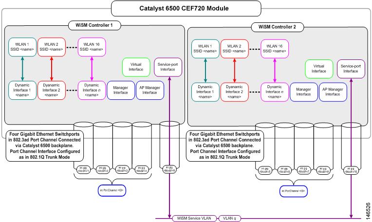
Each Cisco wireless LAN controller can support up to 512 operator-defined interfaces. Each operator-defined interface controls VLAN and other communications between controllers and all other network devices connected to an individual physical port.
Up to 16 WLANs can be configured per controller. A WLAN designation associates an SSID to an interface and is configured with security, quality of service (QoS), radio policies, and other parameters specific to the WLAN.
Figure 1 illustrates the typical relationship between the ports and the interfaces.
Figure 1 Relationship Between Ports and Interfaces
Another Cisco unified wireless network architecture concept is mobility group. A mobility group is a cluster of controllers. Wireless devices can roam seamlessly within a mobility group. WLC devices within a mobility group also coordinate dynamic radio management calculations for the access points within the mobility group. For Cisco WiSM, both the WiSM modules should be part of the same mobility group for seamless routing among 300 access points. Each Catalyst 6500 chassis supports five Cisco WiSMs (up to 1500 access points). Each Cisco wireless LAN controller cluster supports 12 Cisco WiSMs (up to 3600 access points).
Note
Configuration Rules
When structured as the logical network diagram shown in Figure 1, the following rules apply to configure the Cisco WiSM.
General Rules
These general rules apply:
•
•
•
Interface Assignment Rules
These management interface rules apply:
•
•
This AP manager interface rules applies:
•
These dynamic interface rules apply:
•
•
Configuration Overview
The following procedures are required to set up the Cisco WiSM:
•
•
•
Verifying the Hardware and Software
Before configuring the Cisco WiSM, verify that the proper versions of the hardware and software are installed for the following:
•
•
•
•
Hardware Components
The Catalyst 6500 or Cisco 7600 chassis in which the Cisco WiSM is installed needs a Supervisor 720 module. The supported slots for the Cisco WiSM are shown in the WiSM Troubleshooting FAQ (document 70608) at this URL:
http://www.cisco.com/en/US/products/hw/switches/ps708/products_qanda_item09186a00806e39b7.shtmlThe Cisco WiSM module needs 254.94 Watts for its operation. Ensure that your Catalyst chassis provides the necessary power. All Catalyst 6500 chassis except the Catalyst 6503 require the fan tray 2 module, which in turn requires the 2500-W power supply for proper operation. The 2500-W power supplies use a 20-A circuit with a NEMA plug.
Before proceeding, ensure that the module is detected by the supervisor and that the status LED is green. If the status LED is not green, the supervisor may not have the correct software release to detect the Cisco WiSM module or to detect a hardware problem in the module. The output from a show module command specifies that the Cisco WiSM module is installed in slot 3.
Sup720#sh modMod Ports Card Type Model Serial No.--- ----- -------------------------------------- ------------------ -----------3 10 WiSM WLAN Service Module WS-SVC-WiSM-1-K9 SAD100604C44 48 48-port 10/100 mb RJ45 WS-X6148-45AF SAL08154UT35 2 Supervisor Engine 720 (Active) WS-SUP720-3BXL SAL0913827EMod MAC addresses Hw Fw Sw Status--- ---------------------------------- ------ ------------ ------------ -------3 0016.4625.c838 to 0016.4625.c847 1.2 12.2(14r)S5 12.2(18)SXF2 Ok4 0011.206d.7ef0 to 0011.206d.7f1f 1.0 5.4(2) 8.5(0.46)RFW Ok5 0013.7f0d.114c to 0013.7f0d.114f 4.3 8.1(3) 12.2(18)SXF2 OkMod Sub-Module Model Serial Hw Status---- --------------------------- ------------------ ----------- ------- -------3 Centralized Forwarding Card WS-SVC-WISM-1-K9-D SAD100605LG 1.2 Ok4 IEEE Voice Daughter Card WS-F6K-FE48-AF SAD082007YH 1.1 Ok5 Policy Feature Card 3 WS-F6K-PFC3BXL SAL091597AS 1.6 Ok5 MSFC3 Daughterboard WS-SUP720 SAL09158X9K 2.3 OkMod Online Diag Status---- -------------------3 Pass4 Pass 5 PassSoftware Components
The minimum software requirements to support Cisco WiSM module are given in Table 2:
Note
Topology Example
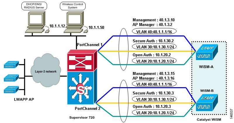
Figure 2 illustrates the topology on which the configuration examples in this document are based.
Figure 2 Topology Example
In the configuration example, the Cisco WiSM is installed in slot 3 of the Catalyst 6506 chassis. Two WLANs are configured: one for open authentication (SSID "open") and one for EAP authentication (SSID "secure"). Dynamic interfaces are created for the open SSID and the EAP SSID and are mapped to the appropriate VLAN. For open SSID, VLAN 20 is used; for EAP SSID, VLAN 30 is used. The management and AP-Manager interfaces are configured to use VLAN 40. All network services (AAA, DHCP, and DNS) are configured on VLAN 1. The WCS is also on VLAN 1.
Configuring Communication Between the Supervisor 720 and Cisco WiSM
If you are using a software release between 12.2.18SXF2 and 12.2.18SXF5, eight Gigabit interfaces are created ranging from Gig3/1 to Gig3/8 after the Cisco WiSM controller is detected by the Supervisor. In this case, the Cisco WiSM controller is installed in slot 3. See Configuring Communication Between the Supervisor 720 and Cisco WiSM Using 12.2.18SXF2 to 12.2.18SXF5
If you are using software release 12.2.18SXF6, you will not be able to configure the Gigabit interfaces. See Configuring Communication Between the Supervisor 720 and Cisco WiSM Using 12.2.18SXF6.
Configuring Communication Between the Supervisor 720 and Cisco WiSM Using 12.2.18SXF2 to 12.2.18SXF5
! -- Create the vlan in the Supervisor 720 to communicate with the management and
ap-manager ports of the Cisco WiSM controller.
Sup720(config)# vlan 40Sup720(config)# description Management VLAN for WiSM! -- Assign an appropriate IP address and subnet mask for VLAN 40Sup720(config)# interface Vlan40Sup720(config-if)# ip address 40.1.1.1 255.255.0.0Sup720(config-if)# no shutdownSup720(config-if)# exit! - Create two port-channel interfaces for the two independent controllers in the Cisco WiSM and assign vlan 40 as the native interface.Sup720(config)# interface Port-channel 1Sup720(config-if)# switchportSup720(config-if)# switchport trunk encapsulation dot1qSup720(config-if)# switchport trunk native vlan 40Sup720(config-if)# switchport mode trunkSup720(config-if)# mls qos trust dscpSup720(config-if)# spanning-tree portfastSup720(config)# interface Port-channel 2Sup720(config-if)# switchportSup720(config-if)# switchport trunk encapsulation dot1qSup720(config-if)# switchport trunk native vlan 40Sup720(config-if)# switchport mode trunkSup720(config-if)# mls qos trust dscpSup720(config-if)# spanning-tree portfast! -- Configure the below Giga-bit interfaces as trunk ports with vlan 40 as the native vlan (please make sure that native vlan is not getting tagged while doing the Cisco WiSM configuration).The Gigabit interfaces 3/1 to 4 correspond to the first controller in Cisco WiSM and should be a member of channel group one.
Sup720(config)# interface range GigabitEthernet3/1-4Sup720(config-if)# switchportSup720(config-if)# switchport trunk encapsulation dot1qSup720(config-if)# switchport mode trunkSup720(config-if)# switchport trunk native vlan 40Sup720(config-if)# spanning-tree portfastSup720(config-if)# channel-group 1 mode onSup720(config-if)# no shutdownSup720(config-if)# exitSimilarly, the Gigabit interfaces 3/5-8 correspond to the second controller in Cisco WiSM and should be a member of channel group two.
Sup720(config)# interface range GigabitEthernet3/5-8Sup720(config-if)# switchportSup720(config-if)# switchport trunk encapsulation dot1qSup720(config-if)# switchport mode trunkSup720(config-if)# switchport trunk native vlan 40Sup720(config-if)# spanning-tree portfastSup720(config-if)# channel-group 2 mode onSup720(config-if)# no shutdownSup720(config-if)# exit! - Create a vlan in the Supervisor 720, this vlan is local to the chassis and is used for communication between Cisco WiSM and Catalyst Supervisor 720 over a Gigabit interface on the Supervisor and service-port in the Cisco WiSM.Sup720(config)# vlan 192! -- Assign an appropriate IP address and subnet mask for VLAN 192Sup720(config)# interface Vlan 192Sup720(config-if)# ip address 192.168.10.1 255.255.255.0Sup720(config-if)# no shutdownSup720(config-if)# exitCreate a DHCP scope for the service port of the Cisco WiSM in Supervisor 720 or on a standalone DHCP server. Then associate the above VLAN for the service port.
Sup720(config)# ip dhcp pool wism-service-portSup720(dhcp-config)#network 192.168.10.0 255.255.255.0Sup720(dhcp-config)#default-router 192.168.10.1! -- Configure the following command to use vlan 192 to communicate with the service-port.Sup720(config)# wism service-vlan 192Use the show wism status command to verify that the Cisco WiSM received an IP address from the DHCP server.
Sup720#sh wism statusService Vlan : 192, Service IP Subnet : 192.168.10.1/255.255.255.0WLANSlot Controller Service IP Management IP SW Version Status----+-----------+----------------+--------------------------+-----------+---------------3 1 192.168.10.3 169.254.1.1 3.2.63.0 Oper-Up3 2 192.168.10.4 169.254.1.1 3.2.63.0 Oper-UpSup720#Configuring Communication Between the Supervisor 720 and Cisco WiSM Using 12.2.18SXF6
Note
Note
Note
! -- Create the vlan in the Supervisor 720 to communicate with the management and
ap-manager ports of the Cisco WiSM controller.
Sup720(config)# vlan 40Sup720(config)# description Management VLAN for WiSM! -- Assign an appropriate IP address and subnet mask for VLAN 40Sup720(config-if)# interface Vlan40Sup720(config-if)# description Management VLAN for WiSMSup720(config-if)# ip address 40.1.1.1 255.255.0.0Sup720(config-if)# no shutdownSup720(config-if)# exitThe Supervisor automatically creates two port-channel interfaces for the two independent controllers in the Cisco WiSM as soon as the module is detected. Usually the port-channels have a high number such as 287 and 288 as shown below.
Sup720#sh ip int brief | inc PortPort-channel1287 unassigned YES unset administratively down downPort-channel1288 unassigned YES unset administratively down downThe following commands can be used to configure the port-channel with native and allowed VLANs. In this case, VLAN 40 is added as the native VLAN.
Note
Sup720(config)# wism module 3 controller 1 ?allowed-vlannative-vlanSup720(config)# wism module 3 controller 1 native-vlan 40Sup720(config)# wism module 3 controller 2 native-vlan 40
Note
no wism module x controller y allowed-vlan 11-1000
The Gigabit interface 3/1 to 4 corresponding to the first controller in the Cisco WiSM are automatically assigned to channel group 287 and the necessary commands are added automatically.
interface GigabitEthernet3/1-4switchportswitchport trunk encapsulation dot1qswitchport trunk native vlan 40switchport mode trunkswitchport nonegotiateno ip addressno snmp trap link-statusmls qos trust cosno cdp enablechannel-group 287 mode onendSimilarly, the Gigabit interfaces 3/5 to 8 corresponding to the second controller in the Cisco WiSM should be members of channel group 288.
interface GigabitEthernet3/5-8switchportswitchport trunk encapsulation dot1qswitchport trunk native vlan 40switchport mode trunkswitchport nonegotiateno ip addressno snmp trap link-statusmls qos trust cosno cdp enablechannel-group 288 mode onendAdditionally, Cisco recommends allowing only VLANs that are configured in the Cisco WiSM through the port-channel and Gigabit interfaces with the following command. Later in the example, VLAN30 is created in the Cisco WiSM and mapped to a secure SSID.
Sup720(config)# wism module 3 controller 1 allowed-vlan 30,40Sup720(config)# wism module 3 controller 2 allowed-vlan 30,40! - Create a vlan in the Supervisor 720, this vlan is local to the chassis and is used for communication between Cisco WiSM and Catalyst Supervisor 720 over a Gigabit interface on the Supervisor and service-port in the Cisco WiSM.Sup720(config)# vlan 192! -- Assign an appropriate IP address and subnet mask for VLAN 192Sup720(config)# interface Vlan 192Sup720(config-if)# ip address 192.168.10.1 255.255.255.0Sup720(config-if)# no shutdownSup720(config-if)# exitCreate a DHCP scope for the service port of the Cisco WiSM in the Supervisor 720 or on a standalone DHCP server. Then associate the above VLAN for the service port.
Sup720(config)# ip dhcp pool wism-service-portSup720(dhcp-config)#network 192.168.10.1 255.255.255.0Sup720(dhcp-config)#default-router 192.168.10.1! -- Configure the following command to use vlan 192 to communicate with the service-port.Sup720(config)# wism service-vlan 192Use the show wism status command to verify that the Cisco WiSM received an IP address from the DHCP server.
Sup720#show wism statusService Vlan : 192, Service IP Subnet 192.168.10.1/255.255.255.0WLANSlot Controller Service IP Management IP SW Version Status----+--------------+----------------+--------------------+------------+--------------3 1 192.168.10.3 0.0.0.0 4.0.155.5Service Port Up3 2 192.168.10.4 0.0.0.0 4.0.155.5Sup720#show wism mod 3 controller 2 statusWiSM Controller 2 in Slot 3Operational Status of the Controller : Oper-UpService VLAN : 192Service Port : 10Service Port Mac Address : 0011.92ff.8742Service IP Address : 192.168.10.4Management IP Address : 40.1.3.15Software Version : 4.0.155.5Port Channel Number : 288Allowed vlan list : 30,40Native VLAN ID : 40WCP Keep Alive Missed : 0Configuring the Cisco WiSM-A
The initial configuration of the Cisco WiSM controller consists of initiating a session from the supervisor. The Cisco WiSM controller is inserted into the appropriate slot and powered up. After the administrator establishes a session with the Cisco WiSM, the basic configuration is completed with the help of the setup script. With the completion of basic configuration, the administrator can configure the Cisco WiSM controller through the console CLI or through the Cisco WiSM controller web-interface. An administrator needs to configure WiSM-A and WiSM-B separately in the Cisco WiSM module, initially from the CLI and then from the web interface. Refer to Configuring Cisco WiSM-B for steps for configuring the WiSM-B.
The system name, Cisco WiSM controller administrative user credentials, the management, the AP manager, virtual interfaces, the mobility group name, one SSID, a RADIUS server, and other options are configured by the setup script. For the management interface, leave the VLAN untagged because it corresponds to the native VLAN on the switch trunk port. For a Cisco WiSM controller, an untagged VLAN is assigned VLAN number 0, which may not correspond to the VLAN number on the switchport. In our example, the switchport's native VLAN is VLAN number 40; but on the Cisco WiSM controller, the management interface is assigned to VLAN 0. In our example, the default values for the other options are accepted.
The syntax for the session command to access to Cisco WiSM from the supervisor is as follows:
Sup720t# session slot <Module # > processor < Proc #>In this example, the module is installed in slot 3, and processor number one is configured first (such as, WiSM-A).
Sup720# sess slot 3 proc 1The default escape character is Ctrl-^ and then x.
You can also type exit at the remote prompt to end the session.
Trying 192.168.10.3 ... Open(WiSM-slot3-1)Welcome to the Cisco Wizard Configuration ToolUse the '-' character to backupSystem Name [Cisco_ff:87:23]:Enter Administrative User Name (24 characters max): adminEnter Administrative Password (24 characters max): *****Service Interface IP Address Configuration [none][DHCP]: dhcpManagement Interface IP Address: 40.1.3.10Management Interface Netmask: 255.255.0.0Management Interface Default Router: 40.1.1.1Management Interface VLAN Identifier (0 = untagged):Management Interface DHCP Server IP Address: 10.1.1.12AP Transport Mode [layer2][LAYER3]: layer3AP Manager Interface IP Address: 40.1.3.2AP-Manager is on Management subnet, using same valuesAP Manager Interface DHCP Server (10.1.1.12):Virtual Gateway IP Address: 1.1.1.1Mobility/RF Group Name: mobile-1Network Name (SSID): secure-1Allow Static IP Addresses [YES][no]: noConfigure a RADIUS Server now? [YES][no]: yesEnter the RADIUS Server's Address: 10.1.1.12Enter the RADIUS Server's Port [1812]:Enter the RADIUS Server's Secret: ciscoEnter Country Code (enter 'help' for a list of countries) [US]:Enable 802.11b Network [YES][no]: YESEnable 802.11a Network [YES][no]: YESEnable 802.11g Network [YES][no]: YESEnable Auto-RF [YES][no]:Configuration saved!The following command verifies the status of all of the above interfaces in the Cisco WiSM.
(WiSM-slot3-1) >show interface summaryInterface Name Port Vlan Id IP Address Type Ap Mgr_______________ _____ ________ ___________ ____ ______ap-manager LAG untagged 40.1.3.2 Static Yesmanagement LAG untagged 40.1.3.10 Static Noservice-port N/A N/A 192.168.10.3 Static Novirtual N/A N/A 1.1.1.1 Static NoAfter executing the above configuration on the Cisco WiSM, execute the following commands in the Supervisor 720 to verify the status of the controller.
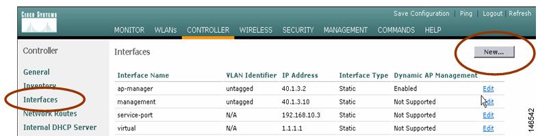
Sup720#show wism statusService Vlan : 192, Service IP Subnet : 192.168.10.1/255.255.255.0WLANSlot Controller Service IP Management IP SW Version Status----+-----------+----------------+----------------+-----------+---------------3 1 192.168.10.3 40.1.3.10 3.2.63.0 Oper-Up3 2 192.168.10.4 169.254.1.1 3.2.63.0 Oper-UpSup720#show wism mod 3 cont 1 statusWiSM Controller 1 in Slot 3Operational Status of the Controller : Oper-UpService VLAN : 192Service Port : 9Service Port Mac Address : 0011.92ff.8722Service IP Address : 192.168.10.3Management IP Address : 40.1.3.10Software Version : 3.2.63.0WCP Keep Alive Missed :0Use the web interface for all configuration of the Cisco WiSM from this point forward. Open the controller web interface by opening the IE browser and point it to the management interface IP address. Only HTTPS is on by default. The URL is https://<management_IP>.
Step 1
Figure 3 Controller > Interfaces
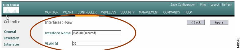
Enter an interface name and VLAN tag. Click Apply. Figure 4 illustrates the configuration of the VLAN 30 interface.
Figure 4 Entering an Interface Name and VLAN Tag
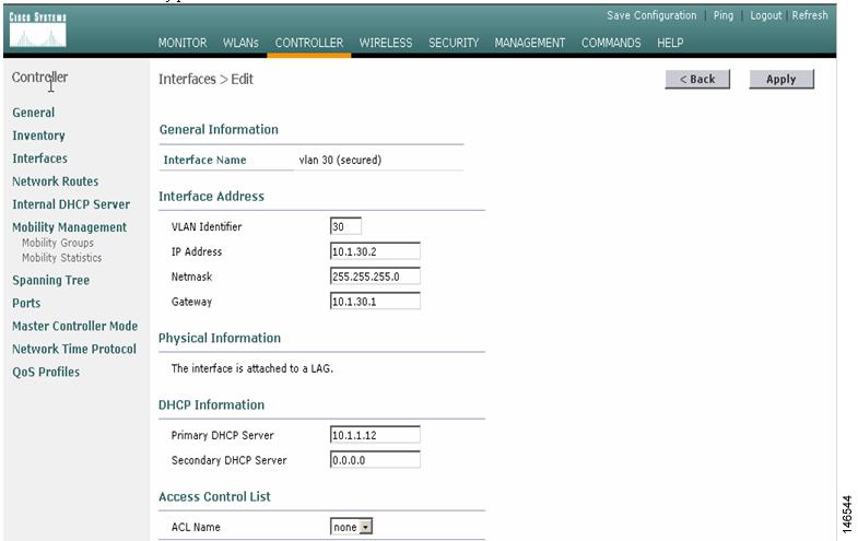
Step 2
Figure 5 Controller > Interfaces > Edit
Repeat this process for each dynamic interface.
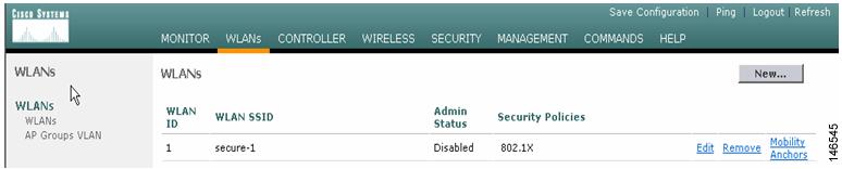
Navigate to WLANs > WLANs > WLANs interface to configure WLANs. The WLAN configured with the setup script secure-1 should be listed (see Figure 6). The WLAN is by default mapped to the management interface and is moved to the VLAN 30 interface in the example.
Step 3
Figure 6 Choosing Edit
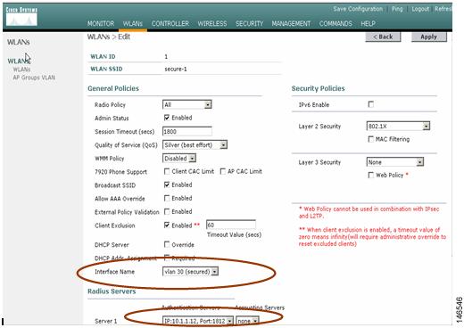
Step 4
Figure 7 Completing the Configuration
Step 5
Configuring Cisco WiSM-B
Establish a session with Cisco WiSM-B from the supervisor and use the initial script to configure the controller.
Sup720# sess slot 3 proc 2The default escape character is Ctrl-^ and then x. You can also type exit at the remote prompt to end the session.
Trying 192.168.10.4... Open(WiSM-slot3-2)Welcome to the Cisco Wizard Configuration ToolUse the '-' character to backupSystem Name [Cisco_0f:f5:a3]:Enter Administrative User Name (24 characters max): adminEnter Administrative Password (24 characters max): *****Service Interface IP Address Configuration [none][DHCP]: dhcpManagement Interface IP Address: 40.1.3.15Management Interface Netmask: 255.255.0.0Management Interface Default Router: 40.1.1.1Management Interface VLAN Identifier (0 = untagged): 0Management Interface Port Num [1 to 4]: 1Management Interface DHCP Server IP Address: 10.1.1.12AP Transport Mode [layer2][LAYER3]: layer3AP Manager Interface IP Address: 40.1.3.16AP-Manager is on Management subnet, using same valuesAP Manager Interface DHCP Server (10.1.1.12):Virtual Gateway IP Address: 1.1.1.1Mobility/RF Group Name: mobile-1Network Name (SSID): secure-1Allow Static IP Addresses [YES][no]: noConfigure a RADIUS Server now? [YES][no]: yesEnter the RADIUS Server's Address: 10.1.1.12Enter the RADIUS Server's Port [1812]:Enter the RADIUS Server's Secret: ciscoEnter Country Code (enter 'help' for a list of countries) [US]:Enable 802.11b Network [YES][no]:Enable 802.11a Network [YES][no]:Enable 802.11g Network [YES][no]:Enable Auto-RF [YES][no]:Configuration saved!Resetting system with new configuration...Sup720#show wism statusService Vlan : 192, Service IP Subnet : 192.168.10.1/255.255.255.0WLANSlot Controller Service IP Management IP SW Version Status----+-----------+----------------+----------------+-----------+---------------3 1 192.168.10.3 40.1.3.10 3.2.63.0 Oper-Up3 2 192.168.10.4 40.1.3.15 3.2.63.0 Oper-UpConfiguring the RADIUS Server for WPA/WPA-2 Authentication
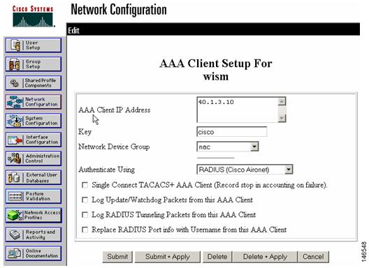
The Cisco WiSM must be defined on the RADUIS server as an AAA client, which allows the Cisco WiSM to authenticate credentials to its database. Using the Cisco Secure ACS RADIUS server, choose Network Configuration, define the IP address of the Cisco WiSM management interface and the shared RADIUS key, and specify RADIUS (Cisco Aironet) as the authentication type as shown in Figure 8.
Figure 8 Specifying Authentication Type
Make sure the second controller is also added in the ACS server as a separate NAS.
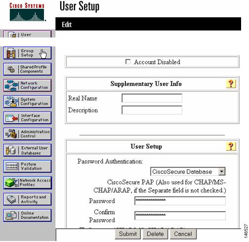
Create some users in the ACS server for initial testing as shown in Figure 9. To configure the Cisco Secure ACS server so that all authentication requests are forwarded to the domain controller or other external database, refer to the Cisco secure configuration guide.
Figure 9 Creating Users in ACS
Configuring the Infrastructure for Access Point Placement
To make the access points register with the controller, put the access points in the same network as the management interface of the Cisco WiSM, in this case, VLAN 40. The example below shows how to configure one port in the switch where the access point is connected.
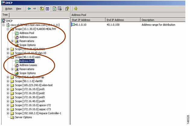
Sup720(config)# interface FastEthernet6/5Sup720(config-if)# switchportSup720(config-if)# switchport access vlan 40Sup720(config-if)# exitCreate the necessary scope in the DHCP server so that the access points can obtain an IP address before registering with the Cisco WiSM. Similarly, create a scope in the DHCP server for the clients to obtain an IP address after it is authenticated from the AAA server. Figure 10 shows scopes for VLAN 40 (used by access points) and VLAN 30 (used by wireless clients).
Figure 10 Creating a Scope in DHCP
After the access point gets an IP address from the DHCP server, it tries to discover the Cisco WiSM and register with it. To verify that if the access points are registered with the Cisco WiSM, do a show ap summary command on the Cisco WiSM.
(WiSM-slot3-1) > show ap sumAP Name Slots AP Model Ethernet MAC Location Port__________ _____ ________ _______________ ______________ ____AP1-cc:50 2 AP1030 00:0b:85:23:cc:50 default_location 29ap:01:88:e0 2 AP-1200 00:0b:85:01:88:e0 pod3 29View the detailed configuration of the access point by entering the show ap config general <AP name> command.
(WiSM-slot3-1) > show ap config general AP1-cc:50Cisco AP Identifier.............................. 5Cisco AP Name.................................... AP1-cc:50AP Regulatory Domain............................. 80211bg: -A 80211a: -ASwitch Port Number .............................. 29MAC Address...................................... 00:0b:85:23:cc:50IP Address Configuration......................... DHCPIP Address....................................... 40.1.0.14IP NetMask....................................... 255.255.0.0Gateway IP Addr.................................. 40.1.1.1Cisco AP Location................................ default_locationCisco AP Group Name..............................Primary Cisco Switch.............................Secondary Cisco Switch...........................Tertiary Cisco Switch............................Administrative State ............................ ADMIN_DISABLEDOperation State ................................. REGISTEREDMirroring Mode .................................. DisabledAP Mode ......................................... LocalRemote AP Debug ................................. DisabledS/W Version .................................... 3.2.63.0Boot Version ................................... 2.1.78.0Mini IOS Version ......--More-- or (q)uit.......................... --Stats Reporting Period .......................... 180LED State........................................ EnabledILP Pre Standard Switch.......................... DisabledILP Power Injector............................... DisabledNumber Of Slots.................................. 2AP Model......................................... AP1030AP Serial Number................................. WCN0916004QAP Certificate Type.............................. Manufacture InstalledConfiguring the WCS and Adding the Cisco WiSM
WCS is the management software used to manage WLC devices and provide advanced management tools like wireless coverage display and location-based services. WCS uses SNMP to manage WLC devices, so the WLC devices need to have SNMP configured correctly.
Step 1
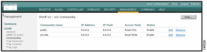
In this example, SNMPv2 is used. Configure SNMPv2 through the Cisco WiSM web interface by navigating to Management > SNMP > Communities. The Cisco WiSM defaults are read-only community public and read-write community private (see Figure 10).
Step 2
Figure 11 Adding or Modifying Communities
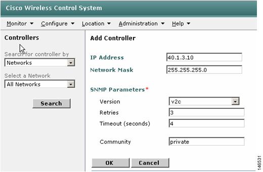
Step 3
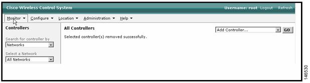
Figure 12 Adding Controllers
Step 4
Figure 13 Verifying IP Reachability
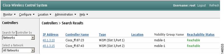
Step 5
Figure 14 WCS Detecting Controllers
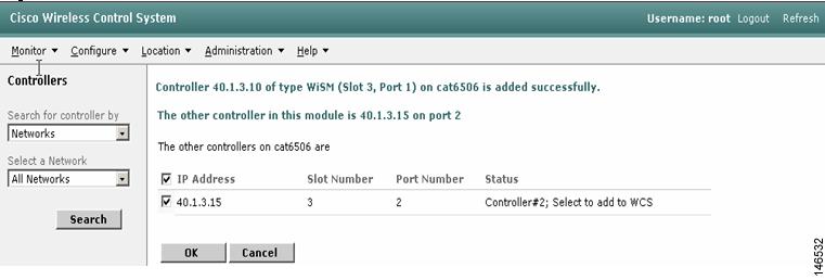
Step 6
Figure 15 Choosing Controllers to Add
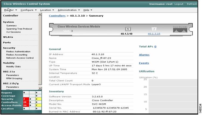
Step 7
Figure 16 Controller Details
Step 8
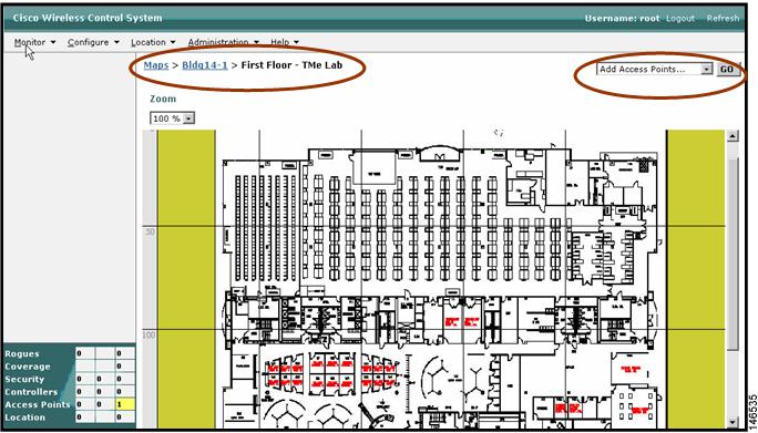
Figure 17 Importing a Floor Plan
Step 9
Figure 18 Placing Access Points onto Floorplan
Step 10
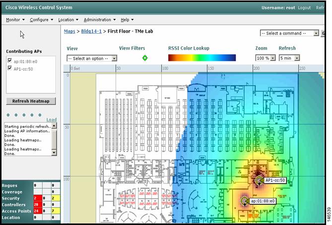
Step 11
Figure 19 Access Point Coverage Area
Configuring DHCP Options 43
Refer to the following appendices in the Deploying Cisco 440X Series Wireless LAN Controllers for various Option 43 configurations:
•
http://www.cisco.com/en/US/docs/wireless/technology/controller/deployment/guide/dep.html#wp1068287
•
http://www.cisco.com/en/US/docs/wireless/technology/controller/deployment/guide/dep.html#wp1069100
•
http://www.cisco.com/en/US/docs/wireless/technology/controller/deployment/guide/dep.html#wp1069651
Upgrading WLC Software
You can upgrade WLC software any of three ways:
•
•
•
Upgrading WLC Software Using the WLC CLI
To upgrade a WLC through the controller CLI, follow these steps:
Step 1
Step 2
Step 3
> transfer download serverip <TFTP Server IP>> transfer download path <path>> transfer download filename <code filename>> transfer download startNote that if you put the code in the TFTP root directory, the "path" parameter is optional.
Step 4
> save configStep 5
> reset systemUpgrading WLC Software Using the WLC Web Interface
To upgrade a controller through the WLC GUI, follow these steps:
Step 1
Step 2
Step 3
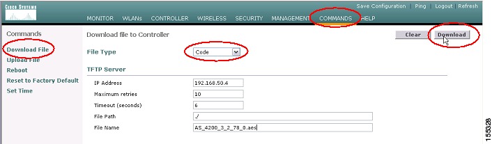
Figure 20 WLC Code Download
Step 4
Figure 21 WLC Code Download
Step 5
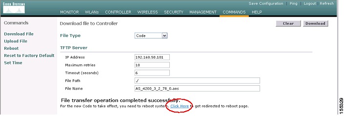
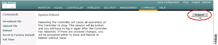
Figure 22 WLC Code Download--Controller Reboot
Step 6
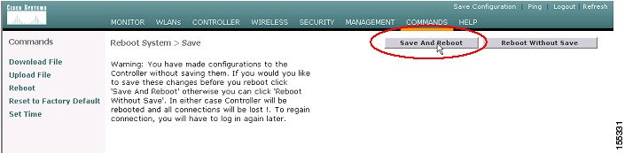
Figure 23 WLC Save and Reboot
When the WLC reboots, you will eventually lose browser connectivity with the controller. Wait a couple of minutes and then refresh the page. A successful page refresh indicates a completed update.
Upgrading WLC Software Using the WCS
To upgrade a WLC using WCS, follow these steps:
Step 1
Step 2
Step 3
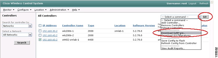
Figure 24 WCS Software Download to WLC
Step 4
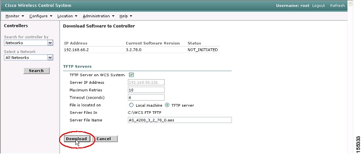
Figure 25 WCS Software Download to WLC
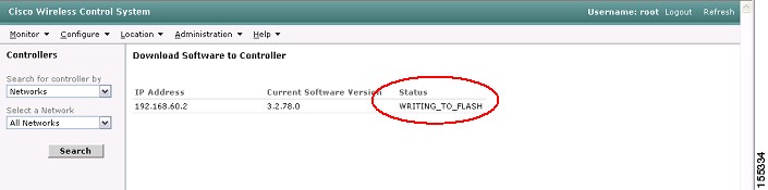
While the code is downloading and the WLC upgrading, you will see status messages in the WCS interface (see Figure 26).
Figure 26 WCS Software Download Status
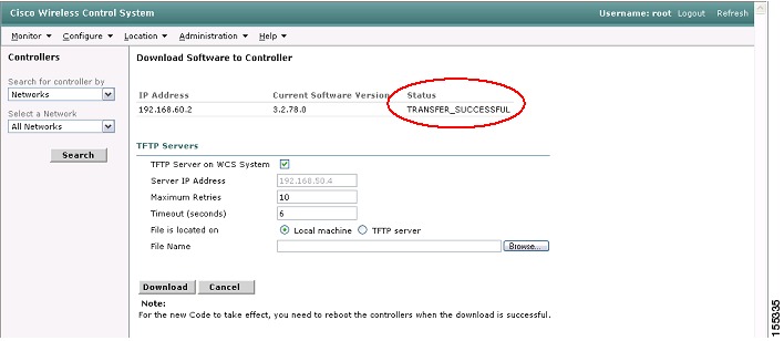
Step 5
Figure 27 WCS Software Download Success
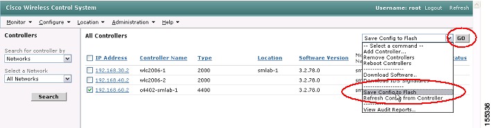
Step 6
Figure 28 WCS Save Configuration to WLC Flash
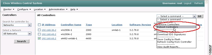
Step 7
Figure 29 WCS Reboot WLC
Best Practices for Upgrading WLC Software
A controller can download a new image without disrupting service but it needs to be rebooted manually to load the new code. Once the new code is loaded on reboot, the upgrade of all access point code is automatically triggered. Cisco controllers currently upgrade four access points at a time. Take this into account when allotting a change window for upgrading your WLC.
To compute the minimum change window, use this formula:
Change Window = Controller reboot time + (Number of APs / 4 )* 3 minutes per APLet's take a worst-case example. Suppose we have a Cisco 4404 controller with 100 access points joined to it. The controller reboot time is approximately 3.5 minutes. So our minimum change window is:
4.5 minutes + (100 APs / 4) * 3 minutes per AP = 78.5 minutes = 1 hour 18.5 minutes.You should allow yourself some time for troubleshooting.
As another best practice, if you have multiple WLC devices in the network, you should keep the software revisions consistent across all WLC devices. This is because an access point down-revs its code when it joins a WLC with a lower code revision than what is currently running on the access point. This is an issue that leads to increased downtime each time an access point joins a new controller. Keep this in mind when you have multiple controllers in the network and redundancy deployed. You should account for this change in your planned service window.
Recovering a Password
To recover a password, refer to:
http://www.cisco.com/en/US/products/ps6308/products_password_recovery09186a008071faa7.shtml
WLC Controller Configuration Backup and Restore
Backup and restore operations for a WLC's configurations can be performed from both the WLC itself and the WCS.
Note
Caution
Managing WLC Configurations Using the WLC Web Interface
Follow these steps to backup WLC Configurations from the WLC Web Interface:
Step 1
Step 2
Step 3
Step 4
Step 5
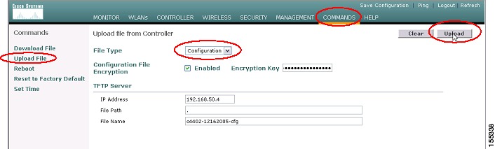
Step 6
Figure 30 WCS Configuration Upload
Step 7
Follow these steps to reload a configuration to a WLC:
Step 1
Step 2
Step 3
Step 4
Step 5
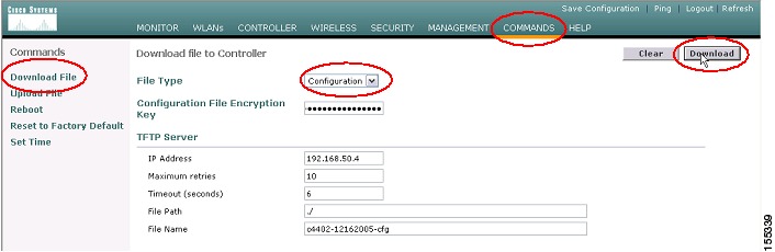
Step 6
Figure 31 WCS Configuration Download to WLC
Step 7
Managing WLC Configurations Using WCS
When a controller is added to WCS, its complete configuration is pulled from the WLC and stored locally. When you use the WCS to change a WLC configuration, it is automatically updated in the WCS database.
If you make a change from on the WLC independent of WCS, you can refresh the configuration on WCS using the following steps:
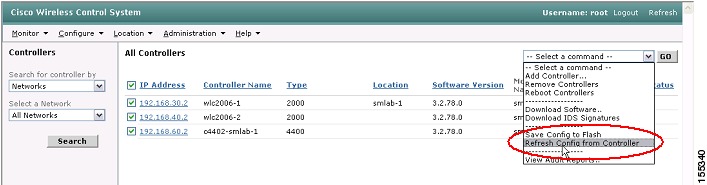
Step 1
Step 2
Figure 32 WCS Refresh Configuration from WLC
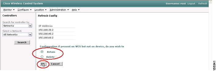
Step 3
Figure 33 WCS Retain Configuration
Step 4
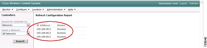
Figure 34 WCS Refresh Configuration Success
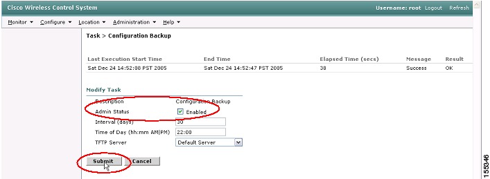
The WCS can also perform scheduled and full on-demand configuration backups:
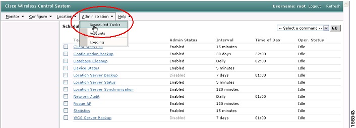
Step 1
Figure 35 WCS Scheduled Configuration Backup
Step 2
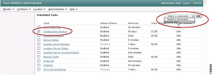
Figure 36 WCS Scheduled Configuration Backup
Step 3
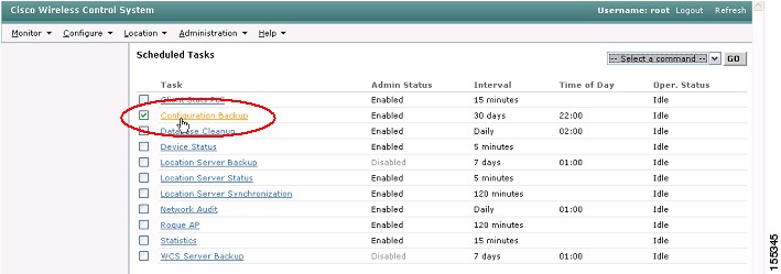
Figure 37 WCS Scheduled Configuration Backup
Step 4
Step 5
Figure 38 WCS Scheduled Configuration Backup
When you want to reset a WLC configuration from the WCS, you may use the Configure | Controllers interface. Select the WLC and then select the appropriate templates to apply to the WLC
Integrating Cisco WiSM and Firewall Service Module
This section includes the following topics:
•
•
Firewall Services Module Overview
The Firewall Services Module (FWSM) is a high-performance, high-speed firewall that can operate up to 5 Gbps. It resides in a single Catalyst 6500 slot and uses VLANs through the backplane to interface with hosts within its domain.
The FWSM supports a maximum of 250 logical (VLAN) interfaces. The FWSM uses VLAN interfaces as its entry and exit points into the networks it serves. The interface schema used is the same as that in the Cisco PIX firewall. Each interface is assigned a security level from 0 to 100, where the lowest security level is 0, and the highest security level is 100. By default, the FWSM has an inside and an outside VLAN interface.
The inside interface has an assigned security level of 100, and the outside interface has an assigned security level of 0. The other logical interfaces that can be created on the FWSM are arbitrarily assigned a security level deemed appropriate by the administrator. These interfaces are often referred to as demilitarized zone (DMZ) interfaces. The definition of what security level is assigned to a particular interface is based on the security policies of that organization.
How the FWSM Works
The main feature of the FWSM architecture is the Adaptive Security Algorithm (ASA). The ASA algorithm establishes some fundamental rules that dictate how the FWSM operates. These rules include the following:
•
•
•
•
•
•
•
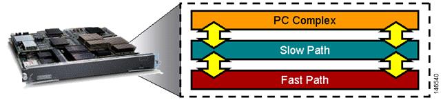
The firewall performs the following three levels of processing (see Figure 39):
•
•
•
Figure 39 Firewall Levels of Processing
PC complex is primarily responsible for any L7 processing and associated management tasks such as the following:
•
•
•
•
•
•
•
The slow and fast path processing is performed by network processors located on the FWSM. Slow path processing includes ACL route lookups, TCP intercept, session management, port address translation allocations, and more. Fast path processing facilitates support for multimedia protocols such as H.323, Real-Time Streaming Protocol (RTSP), Session Initiation Protocol (SIP), and so on, performing Network Address Translation (NAT), DNS guard, fragmentation and virtual reassembly, session identification, and more.
During normal packet processing, a packet passes over the Catalyst 6500 backplane into the services baseboard where it is presented to the firewall fast path processing. If the fast path does not handle the particular function, it passes the packet to the slow path process and then to the PC complex if the slow path process does not handle the packet.
Firewall and Cisco WiSM Implementation Configuration
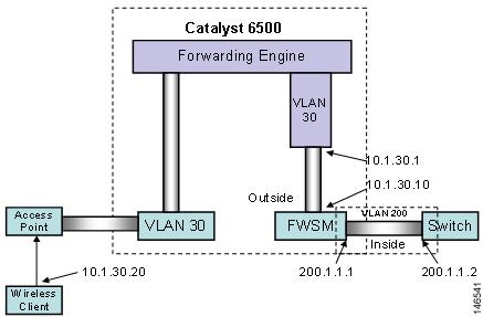
The configuration of the Cisco WiSM described in earlier sections is used as the basis of the FWSM integration example that follows. Figure 40 shows the topology that is created as part of this configuration.
Figure 40 Topology
Configuration of the FWSM begins with a properly installed module. The FWSM can be installed in any of the line card slots in any of the current Catalyst 6500 chassis models. Correct installation of the module results in the following output from a show module command.
Sup720#sh modMod Ports Card Type Model Serial No.--- ----- -------------------------------------- ------------------ -----------3 10 WiSM WLAN Service Module WS-SVC-WISM-1-K9 SAD092504J84 48 48-port 10/100 mb RJ45 WS-X6148-45AF SAL08154UT35 2 Supervisor Engine 720 (Active) WS-SUP720-3BXL SAL0913827E6 6 Firewall Module WS-SVC-FWM-1 SAD090100D9From the CLI output, you can see that the FWSM is installed in slot 6 and has six ports. The six ports mentioned here are not actually external ports but rather logical connections that the module has to the backplane. In fact, these ports are actually the connections between the baseboard and the daughter card.
Before integrating the FWSM with the Cisco WiSM service module, configure the following prerequisites:
•
•
•
•
The access points associate themselves with the controllers when an IP address has been assigned from the DHCP server. The show ap summary command lists these registered LWAPP devices.
The first configuration action assigns VLANs to the FWSM. These VLANs are essentially the firewall interfaces used by the FWSM to interface with the network. VLANs are configured using the VLAN command in the following example:
Cat6506(config)#vlan 30Cat6506(config-vlan)#vlan 200The first VLAN command causes the CLI to enter VLAN configuration mode, which is indicated by the config-vlan extension on the CLI prompt. The use of this command does not preclude the creation of the second VLAN at this configuration level.
After creating the VLANs, you must assign (or bind) them to the FWSM using the firewall vlan-group command.
Cat6506(config)#firewall vlan-group 1 30,200Using this command configures a firewall VLAN group for the FWSM to manage. In this example, it assigns VLANS 30,200 to the VLAN group and assigns a firewall group number (1). This firewall group must now be attached to the FWSM as below:
Cat6506(config)#firewall module 6 vlan-group 1The above command associates the firewall VLAN group you created with the earlier command (identified by firewall group 1) with the FWSM in slot 6.
Up to this point, the Catalyst 6500 CLI has issued commands. Use the FWSM CLI to perform subsequent configurations regarding the setting of policies on the FWSM. The administrator must establish a session with the FWSM using the following command:
Cat6506# session slot 6 processor 1User Access VerificationPassword:Type help or '?' for a list of available commands.FWSM>The session command indicates the module with which you want to establish a session. The processor number at the end of the command should remain as 1. At this stage, you can set up the security policies on your FWSM.
When inside the firewall, configure the VLANs to be used by the firewall along with their IP addresses. The configuration statements are as follows:
FWSM> enablePassword:FWSM# conf tFWSM(config)# nameif vlan30 outside security0FWSM(config)# nameif vlan200 inside security100The first time you enter enable mode in the FWSM (identified by the FWSM# prompt), the enable password is not set. You must press Enter to enter enable mode. You should set the enable password to better restrict access to this operational mode.
First, use the nameif command to define the VLAN interfaces. Each VLAN is identified with a name (in the above case, inside and outside) and assigned a security level. Security levels are assigned a value from 0 to 100, where 0 is the least secure and 100 is the most secure. These values are arbitrary and can be set to any value by the administrator. Next, assign the newly created interfaces an IP address as follows:
FWSM(config)#ip address outside 10.1.30.10 255.255.255.0FWSM(config)#ip address inside 200.1.1.1 255.255.255.0Some additional commands are optional but are useful in the ongoing administration of the FWSM. One of these commands is enable pings. By default, the FWSM does not respond to pings on any of its interfaces. If the outside or inside interface of the FWSM needs to be pinged, you must enable this on the FWSM. For example, you can enable ping replies on the inside interface (and optionally outside) of the FWSM as follows:
FWSM(config)#icmp permit any insideFWSM(config)#icmp permit any outsideCreate policies on the firewall using access control lists. In our example, we want to permit traffic from 200.1.1.0 (inside the firewall) to 10.1.30.0 (where the wireless client resides) in the following manner:
FWSM(config)#access-list 101 extended permit tcp 200.1.1.0 255.255.255.0 10.1.30.0
255.255.255.0
As in Cisco IOS software, an implicit "deny all" message can appear at the end of this access list. You must then apply the access list to the outside interface as follows:
FWSM(config)#access-group 101 in interface insideTraffic flows from the wireless domain back to the inside in the following manner:
FWSM(config)#access-list 102 extended permit tcp 10.1.30.0 255.255.255.0 200.1.1.0
255.255.255.0
Now, create a VRF instance as follows. This is the first step towards configuring the VRF on the tunnel interface.
c6506(config)#ip vrf wism-fwsmc6506(config-vrf)#rd 1:100c6506(config-vrf)#route-target export 1:100c6506(config-vrf)#route-target import 1:100With this set of commands, a VRF instance called wism-fwsm is created. A route descriptor (RD) of 1:100 is added to each of the IPV4 prefixes in the forwarding table. These RDs associate the prefixes with this VRF instance.
Next, apply the VRF to the VLAN interface as follows:
c6506#conf tEnter configuration commands, one per line, and end with CNTL/Z.
c6506(config)#interface vlan 30c6506(config)#ip vrf forwarding wism-fwsm% Interface Vlan30 IP address 10.1.30.1 removed due to disabling VRF wism-fwsmWhen applying the VRF to the VLAN interface, the IP address is removed. Add the IP address back onto the interface before proceeding with the next step.
VLAN interface 201 must also be added into the same VRF so that the tunnel interface can see VLAN 201 in its route table and thus forward data onto the FWSM.
To finish the VRF configuration, install a static route in the VRF, and the global routing table points all traffic inbound from the wireless clients into the switch, to the firewall, and vice versa.
c6506#conf tEnter configuration commands, one per line. End with CNTL/Z.c6506(config)# ip route vrf wism-fwsm 200.1.1.0 255.255.255.0 10.1.30.10The first configuration statement adds a static route into the VRF instance called wism-fwsm. It states that any data destined to network 200.1.1.0 is forwarded to the next hop address 10.1.30.10 (the VLAN interface on the FWSM). This static route is only applicable to any interface using that VRF.
The complete configuration on the 6500 is shown below:
Note
Note
Sup720#show runBuilding configuration...Current configuration : 8069 bytes!upgrade fpd autoversion 12.2service timestamps debug uptimeservice timestamps log uptimeno service password-encryptionservice counters max age 10!hostname cat6506!enable password cisco!no aaa new-modelclock timezone PDT -7firewall multiple-vlan-interfacesfirewall module 6 vlan-group 1firewall vlan-group 1 30,200ip subnet-zero!!ip dhcp excluded-address 192.168.10.1 192.168.10.2!ip dhcp pool wism-service-portnetwork 192.168.10.0 255.255.255.0default-router 192.168.10.1!ip dhcp pool net!ip vrf wism-fwsmrd 1:100route-target export 1:100route-target import 1:100!no ip domain-lookupipv6 mfib hardware-switching replication-mode ingressmls ip multicast flow-stat-timer 9no mls flow ipno mls flow ipv6no mls acl tcam share-globalmls cef error action freeze!!wism service-vlan 192!interface Port-channel1description wism-pod1switchportswitchport trunk encapsulation dot1qswitchport trunk native vlan 40switchport mode trunkmls qos trust dscpspanning-tree portfastno ip address!interface Port-channel2switchportswitchport trunk encapsulation dot1qswitchport trunk native vlan 40switchport mode trunkmls qos trust dscpspanning-tree portfastno ip address!interface Port-channel3switchportswitchport trunk encapsulation dot1qswitchport trunk native vlan 40switchport mode trunkmls qos trust dscpspanning-tree portfastno ip address!interface GigabitEthernet3/1switchportswitchport trunk encapsulation dot1qswitchport trunk native vlan 40switchport mode trunkno ip addressmls qos trust dscpspanning-tree portfastchannel-group 1 mode on!interface GigabitEthernet3/2switchportswitchport trunk encapsulation dot1qswitchport trunk native vlan 40switchport mode trunkmls qos trust dscpspanning-tree portfastno ip addresschannel-group 1 mode on!interface GigabitEthernet3/3switchportswitchport trunk encapsulation dot1qswitchport trunk native vlan 40switchport mode trunkmls qos trust dscpspanning-tree portfastno ip addresschannel-group 1 mode on!interface GigabitEthernet3/4switchportswitchport trunk encapsulation dot1qswitchport trunk native vlan 40switchport mode trunkmls qos trust dscpspanning-tree portfastno ip addresschannel-group 1 mode on!interface GigabitEthernet3/5switchportswitchport trunk encapsulation dot1qswitchport trunk native vlan 40switchport mode trunkmls qos trust dscpspanning-tree portfastno ip addresschannel-group 2 mode on!interface GigabitEthernet3/6switchportswitchport trunk encapsulation dot1qswitchport trunk native vlan 40switchport mode trunkmls qos trust dscpspanning-tree portfastno ip addresschannel-group 2 mode on!interface GigabitEthernet3/7switchportswitchport trunk encapsulation dot1qswitchport trunk native vlan 40switchport mode trunkmls qos trust dscpspanning-tree portfastno ip addresschannel-group 2 mode on!interface GigabitEthernet3/8switchportswitchport trunk encapsulation dot1qswitchport trunk native vlan 40switchport mode trunkmls qos trust dscpspanning-tree portfastno ip addresschannel-group 2 mode on!interface FastEthernet4/1switchportno ip address!< snip >!interface FastEthernet4/13switchportswitchport access vlan 40no ip address!interface FastEthernet4/14switchportswitchport access vlan 40no ip address!< snip >!interface FastEthernet4/25description Host for the inside of FWSM 200.1.1.20switchportswitchport access vlan 200no ip address!interface Vlan1ip address 10.1.1.2 255.255.255.0!interface Vlan30ip vrf forwarding wism-fwsmip address 10.1.30.1 255.255.255.0ip helper-address 10.1.1.11!interface Vlan40ip address 40.1.1.1 255.255.0.0ip helper-address 10.1.1.11!interface Vlan192ip address 192.168.10.1 255.255.255.0!interface Vlan200ip address 200.1.1.2 255.255.255.0!!router eigrp 100network 10.0.0.0network 192.168.0.0no auto-summary!ip classlessip route vrf wism-fwsm 200.1.1.0 255.255.255.0 10.1.30.10!no ip http server!!control-plane!dial-peer cor custom!line con 0line vty 0 4password ciscono login!endcat6506#The complete configuration on the FWSM is shown below:FWSM# show run: Saved:FWSM Version 2.3(2)nameif vlan30 outside security0nameif vlan200 inside security100enable password 8Ry2YjIyt7RRXU24 encryptedpasswd 2KFQnbNIdI.2KYOU encryptedhostname FWSMftp mode passivefixup protocol dns maximum-length 512fixup protocol ftp 21fixup protocol h323 H225 1720fixup protocol h323 ras 1718-1719fixup protocol rsh 514fixup protocol sip 5060no fixup protocol sip udp 5060fixup protocol skinny 2000fixup protocol smtp 25fixup protocol sqlnet 1521namesaccess-list deny-flow-max 4096access-list alert-interval 300access-list 102 extended permit tcp any host 10.1.30.254 eq wwwaccess-list 101 extended permit tcp 200.1.1.0 255.255.255.0 any eq wwwpager lines 24logging buffer-size 4096mtu outside 1500mtu inside 1500ip address outside 10.1.30.10 255.255.255.0ip address inside 200.1.1.1 255.255.255.0no failoverfailover lan unit secondaryfailover polltime unit 1 holdtime 15failover polltime interface 15failover interface-policy 50%icmp permit any outsideicmp permit any insideno pdm history enablearp timeout 14400global (outside) 1 interfacenat (inside) 1 0.0.0.0 0.0.0.0static (inside,outside) 10.1.30.254 200.1.1.20 netmask 255.255.255.255access-group 102 in interface outsideaccess-group 101 in interface inside!interface outside!interface inside!route outside 0.0.0.0 0.0.0.0 10.1.30.1 1timeout xlate 3:00:00timeout conn 1:00:00 half-closed 0:10:00 udp 0:02:00 icmp 0:00:02 rpc 0:10:00 h323 0:05:00 h225 1:00:00 mgcp 0:05:00 sip 0:30:00 sip_media 0:02:00timeout uauth 0:05:00 absoluteaaa-server TACACS+ protocol tacacs+aaa-server TACACS+ max-failed-attempts 3aaa-server TACACS+ deadtime 10aaa-server RADIUS protocol radiusaaa-server RADIUS max-failed-attempts 3aaa-server RADIUS deadtime 10aaa-server LOCAL protocol localno snmp-server locationno snmp-server contactsnmp-server community publicsnmp-server enable traps snmpfloodguard enablefragment size 200 outsidefragment chain 24 outsidefragment size 200 insidefragment chain 24 insidetelnet timeout 5ssh timeout 5terminal width 80Cryptochecksum:fd9eac84597419d0969d1d906705d122: end[OK]FWSM#: endThe configuration is now complete. Data from the wireless clients is forwarded to the tunnel interface and then forwarded to the outside interface of the FWSM. The firewall now needs its security policies applied to determine what traffic can or cannot pass.
Integrating Cisco WiSM and VPN Service Module
This section includes the following topics:
•
•
•
VPNSM Overview
The VPN Services Module (VPNSM) was introduced as a high-performance VPN option to further extend the existing VPN portfolio of products from Cisco. The VPNSM is part of the Catalyst 6500 service module family, which comprises the Firewall Services Module (FWSM), Content Switching Module (CSM), Intrusion Detection System Module (IDSM), Network Analysis Module (NAM), and the Secure Socket Layer Module (SSL).
The VPNSM, like other service modules, is geared to provide high-performance services accelerated by hardware offering up to 1.9 Gbps of Triple Data Encryption Standard (3DES) data (at 500-byte packets) and 1.6 Gbps of 3DES traffic at a smaller packet size of 300 bytes.
The VPNSM offers the following features:
•
•
•
•
•
•
•
•
•
•
•
•
•
How VPNSM Works
Unlike some of the other Catalyst 6500 services modules, the VPNSM does not rely on either the SPAN facility or VACL capture facility to process VPN traffic. The VPNSM must be placed in the path of traffic so that it can apply VPN processing to any traffic matching the configured ACL criteria; therefore, you should carefully consider design and implementation of the VPNSM.
Physical modifications to the network may be required in order to place the VPNSM in the path of the necessary traffic. Also, unlike many of the other service modules, the VPNSM is configured directly from the Cisco IOS CLI. There is no need to access (or Telnet) into the module to configure it.
When a VPN module is installed into a Catalyst 6500/7600 chassis, it determines whether Catalyst 6500 interfaces and ports in that chassis belong to the inside network (local LAN) or the outside network (outside world). The determination of whether ports are inside or outside impacts the way VLANs are set up and how they interact with VPNSM. All ports that connect to the outside world (external networks) are referred to as Catalyst outside ports, and those within the local LAN network are referred to Catalyst inside ports. If an Ethernet 10/100 port (for example, port 5) on module 3 (port 3/5) was connected to an inside server, then that port is designated as a Catalyst inside port. If the same port were connected to the WAN router, then that port is designated as a Catalyst outside port.
While the VPN module has no external (physical) ports, it has two logical ports that connect the VPN module to the backplane of the Catalyst 6500/7600. These two logical ports are configured as Gigabit Ethernet (GE) ports from the command line interface (CLI). The VPN ports can be seen from the following show module command from the supervisor CLI:
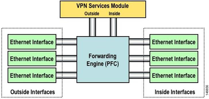
c6506# sh modMod Ports Card Type Model Serial No.--- ----- -------------------------------------- ------------------ -----------2 2 IPSec VPN Accelerator WS-SVC-IPSEC-1 SAD0837063H3 10 WiSM WLAN Service Module= WS-SVC-WiSM-1-K9 SAD092504J84 48 48-port 10/100 mb RJ45 WS-X6148-45AF SAL08154UT35 2 Supervisor Engine 720 (Active) WS-SUP720-3BXL SAL0913827E6 6 Firewall Module WS-SVC-FWM-1 SAD090100D9Mod MAC addresses Hw Fw Sw Status--- ---------------------------------- ------ ------------ ------------ -------2 0003.e470.05cc to 0003.e470.05cf 1.3 7.2(1) 8.5(0.46)RFW Ok3 0001.0002.0003 to 0001.0002.0012 0.1 12.2(14r)S5 12.2(PP_R31_ Ok4 0011.206d.7ef0 to 0011.206d.7f1f 1.0 5.4(2) 8.5(0.46)RFW Ok5 0013.7f0d.114c to 0013.7f0d.114f 4.3 8.1(3) 12.2(PP_R31_ Ok6 0012.8005.d418 to 0012.8005.d41f 3.0 7.2(1) 2.3(2) OkMod Sub-Module Model Serial Hw Status---- --------------------------- ------------------ ----------- ------- -------3 Centralized Forwarding Card FARFEL SAD092608SU 0.2 Ok4 IEEE Voice Daughter Card WS-F6K-FE48-AF SAD082007YH 1.1 Ok5 Policy Feature Card 3 WS-F6K-PFC3BXL SAL091597AS 1.6 Ok5 MSFC3 Daughterboard WS-SUP720 SAL09158X9K 2.3 OkMod Online Diag Status---- -------------------2 Pass3 Pass4 Pass5 Pass6 PassThe VPN designates one of these logical GE ports as the VPN inside port and the other logical GE port as the VPN outside port. The designation of which VPN port is the inside and outside port is fixed and cannot be changed. Port 1 is always treated as the VPNSM inside port, and Port 2 is always treated as the VPNSM outside port. The VPN inside port is used to transfer data to and from the Catalyst inside ports, and the VPN outside port is used to transfer data to and from the Catalyst outside ports, as shown in Figure 22.
Figure 41 Catalyst and VPN Inside and Outside Ports
Normally, the Catalyst outside ports are connected either directly to the LAN/WAN or to a WAN device that connects to an external network. The VPN outside port is grouped with the Catalyst outside ports so the VPN processing of packets comes into the VPNSM. You need to place the VPN outside port and the Catalyst outside ports in the same VLAN to accomplish this. This VLAN is normally set as a Layer 2 VLAN, and no associated VLAN interface is set on the MSFC. However, to interoperate with the Cisco WiSM, the VLAN interface that is associated with the VPN outside interface is set up as a Layer 3 interface.
An interface VLAN is created on the MSFC. This port is placed in the same VLAN as the VPN inside port. This interface VLAN has the security configuration assigned to it. For instance, any crypto maps that are configured are usually applied to this VLAN interface. Do not add any other ports to this VLAN. Cisco recommends that any Catalyst inside ports use the PFC to L3 switch data to the VPNSM.
VPNSM Configuration with the Cisco WiSM
To integrate Cisco WiSM with the VPNSM, we use the following process: VRFs on the ingress tunnel interface push ingress VPN packets to the outside VPNSM interface as the next hop. The VRF may need to be primed with a static route that has the destination VPN peer address as its next hop. Other traffic not destined for the VPNSM is forwarded as required.
This configuration assumes that the Cisco WiSM setup described earlier in this paper is working and that the wireless client can successfully authenticate and register with the network.
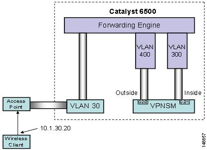
The integration of the VPNSM with the wireless setup is based on the diagram in Figure 23.
Figure 42 Topology of the VPNSM with the Cisco WiSM
First, we need to explore the basic VPN configuration statements that allows a VPN client to connect with the VPNSM. Those key configuration statements are listed below:
c6506(config)#crypto isakmp policy 1c6506(config-isakmp)#encr 3desc6506(config-isakmp)#hash md5c6506(config-isakmp)#auth pre-sharec6506(config-isakmp)#group 2c6506(config-isakmp)#exitThis set of statements defines a crypto policy, which is used to define the crypto environment that connects the VPN client with the VPNSM. This policy defines the use of the 3DES algorithm for encrypting traffic. The MD5 hash algorithm is used to protect passwords; and group 2 refers to the use of Diffie-Hellman Group 2 (1024 bit) key generation.
The following statement defines the ISAKMP key that the VPN client uses to establish a VPN session with the VPNSM:
c6506(config)#crypto isakmp key cisco1 address 0.0.0.0 0.0.0.0The key is defined as cisco1. The address component of the statement sets classification criteria for the address of the incoming VPN client address. The use of 0.0.0.0 is a catch-all and provides a match for all incoming connections.
The following statements are ISAKMP tuning values used to set the interval between keepalives and the amount of idle time allowed in the ISAKMP setup before the session is closed:
c6506(config)#crypto isakmp keepalive 10c6506(config)#crypto isakmp xauth timeout 45The following set of statements defines the attributes using the group access information name of vpnsm-with-remclient. The attributes include the key and the address pool used when assigning an IP address to the client.
c6506(config)#crypto isakmp client configuration group wism-vpnsmc6506(config-isakmp-group)#key cisco1c6506(config-isakmp-group)#domain cisco.comc6506(config-isakmp-group)#pool pool-1c6506(config-isakmp-group)#crypto dynamic-map dynmap 1c6506(config-crypto-map)#exitAfter the initial VPN tunnel has been set up, the following transform set defines a set of crypto attributes for data transmission. It defines the usable encryption algorithm options to be negotiated between the VPNSM and the VPN client for this VPN session.
c6506(config)#crypto ipsec transform-set transform-1 esp-3des esp-sha-hmacThe following crypto map indicates the transform set to use. The use of reverse route is to instruct the switch to install a route into the local routing table that points back to the client on successful VPN setup.
c6506(config)#crypto dynamic-map dynmap 1c6506(config-crypto-map)#set transform-set transform-1c6506(config-crypto-map)#reverse-routec6506(config-crypto-map)#exitc6506(config)#crypto map client-map client authentic list vpnusersc6506(config)#crypto map client-map isakmp authorization list vpnsm-with-remclientc6506(config)#crypto map client-map client configuration address respondc6506(config)#crypto map client-map 1 ipsec-isakmp dynamic dynmapThe final collection of crypto map statements pull many of the configured elements above into a composite crypto map that is bounded to the port from which the remote client peers.
Next, the interface with which the VPN client peers must be defined. In the above example, VLAN 300 has been created for this purpose. It is set up as a Layer 3 interface with an IP address assigned to it. It uses the crypto map command to identify which crypto policy is being used. The crypto policy indicates which crypto features are available to set up and manage data through the VPN tunnel.
The following local pool command defines a set of IP addresses that are assigned to each authenticated incoming user. In the example above, an address pool named remote-pool has been set up to serve addresses from a 172.16 network. Addresses 10.10 through 10.254 are available for this pool.
c6506(config)#ip local pool pool-1 172.16.10.10 172.16.10.254The following set of statements authenticates incoming VPN connections to the VPNSM. They reference some of the group definitions stated earlier in this configuration section.
c6506(config)#aaa new-modelc6506(config)#aaa authen login def localc6506(config)#aaa authen login vpnusers local nonec6506(config)#aaa author network vpnusers localNow configure the VPNSM logical interfaces as follows:
c6506(config)#interface g2/1c6506(config-if)#no ip addressc6506(config-if)#switchportc6506(config-if)#switchport trunk encap dot1qc6506(config-if)#switchport trunk allowed vlan 300c6506(config-if)#switchport mode trunkc6506(config-if)#int g2/2c6506(config-if)#no ip addressc6506(config-if)#switchportc6506(config-if)#switchport trunk encap dot1qc6506(config-if)#switchport trunk allowed vlan 400c6506(config-if)#switchport mode trunkIn the above example, the VPNSM has been installed in slot 2. Port is always deemed the inside VPN port, and Port 2 is the outside VPN port. This nomenclature is fixed (internal to the VPNSM) and cannot be changed. Both ports are set up as 802.1q trunk ports and have no IP address associated with them.
The main configuration option specifies which VLANs the user wants to allow across each of the ports. The inside port VLAN must match the VLAN interface which has the crypto maps applied to it. The permitted VLANs on the VPNSM outside port must match the VLAN on which the outside switch port is located.
c6506(config)#int vlan 300c6506(config-if)#ip add 22.1.1.2 255.255.255.0c6506(config-if)#crypto map client-mapc6506(config-if)#crypto engine slot 2c6506(config)#interface Vlan400c6506(config-if)#ip address 22.1.1.3 255.255.255.0c6506(config-if)#00:57:14: %CRYPTO: Wrong config: MAC addresses are the same between VLAN 300 and VLAN 400.c6506(config-if)#mac-add 0000.cccc.ddddc6506(config-if)#crypto connect vlan 300c6506(config-if)#crypto engine slot 2When you configure the VPNSM for normal operation, each VLAN that contains ports receiving traffic from the wireless world needs to have the crypto connect command applied to it.
In the configuration example above, VLAN interface 400 is the interface facing the outside. The crypto connect vlan command ties this port to the VPN inside port. The VLAN specified as part of the crypto connect command is the VLAN interface where the crypto map is applied (containing the crypto policy for incoming sessions). The first time a crypto connect vlan command is applied in the configuration, a hardware crypto engine that sits on the VPNSM is activated.
VLAN 400 also needs to operate in Layer 3 mode; therefore, you need an IP address to route packets from the tunnel interface to the outside interface. However, the VPNSM continues to operate at Layer 2, so the IP address must be in the same subnet as the inside interface. Using VRF, you can assign two IP addresses in the same subnet to two different VLAN interfaces.
In addition, a different MAC address for this interface is needed. When defining a VLAN interface, the MAC is assigned by the supervisor to be part of the static pool on the box, and all the virtual interfaces get the same MAC address by default. Generally, when interfaces are in different subnets, this is not a problem. However, with VLAN interfaces that are connected to the VPNSM, at least one interface between VLAN interface 300 and 300 must be manually configured with a MAC address.
The following VRF configuration is necessary for the tunnel interface and for the interface VLAN outside:
c6506(config)#ip vrf wism-vpnsmc6506(config-vrf)#rd 2:100c6506(config-vrf)#route-target export 2:100c6506(config-vrf)#route-target import 2:100With this set of commands, we have created a VRF instance called wism-vpnsm. A route descriptor (RD) of 2:100 is added to each of the IPV4 prefixes in the forwarding table to associate them with this VRF instance.
Next, the VRF needs to be applied to the tunnel interface and to the outside VLAN
interface that is associated with the outside VPNSM interface. This is done as follows:
c6506#conf tEnter configuration commands, one per line. End with CNTL/Z.c6506(config)#interface vlan 30c6506(config-if)#ip vrf forwarding wism-vpnsmc6506(config-if)#ip address 10.1.30.1 255.255.255.0c6506(config-if)#interface vlan400c6506(config-if)#ip vrf forwarding wism-vpnsm% Interface Vlan400 IP address 22.1.1.3 removed due to enabling VRF wism-vpnsmc6506(config-if)#ip address 22.1.1.3 255.255.255.0When the VRF is applied to the interface, the IP address is removed. The IP address needs to be reapplied onto the interface before you proceed to the next step.
The WLAN traffic coming from the VLAN interface is destined to the IP address of the VPN server (22.1.1.2 in this example, which is the IP address on the inside VLAN of the VPNSM). The router checks its VRF wism-vpnsm routing table and sees that this destination IP address is directly connected to the outside interface (VLAN 400). If IPsec is the only traffic you receive from the tunnel interface, then no static route statement in the VRF domain is needed. All packets are routed out of interface VLAN 400 because it is in the same subnet as the destination. However, if you have something besides encrypted traffic, you need to use a vrf static route in the VRF domain to forward the packets where appropriate.
For the reverse path of traffic destined to the wireless client, the reverse route injection feature configured with crypto dynamic-map ensures that a host route for the VPN client gets installed in the default VRF routing table, pointing to the inside interface of the VPN module.
Some final configuration statements must be applied to complete the configuration. A static ARP entry must be added into the VRF MAC table for the inside VLAN interface and also for the VLAN outside interface. Because ARP is not supported through the VPN blade, the supervisor needs the IP/MAC mapping to forward the packets.
c6506(config)#arp vrf wism-vpnsm 22.1.1.2 0005.dc56.9400 ARPAc6506(config)#arp 22.1.1.3 0000.cccc.dddd ARPAAlso, a username and password needs to be defined for when the VPN client connects to the VPN services module. For this example, simply use the cisco username and password as follows:
c6506(config)#username cisco password 0 ciscoThe final configuration for the 6500 is the following:
Note
c6506#show runBuilding configuration...Current configuration : 10194 bytes!upgrade fpd autoversion 12.2service timestamps debug uptimeservice timestamps log uptimeno service password-encryptionservice counters max age 10!hostname cat6506!boot system flash disk0:s72033-adventerprisek9_wan_dbg-mz.PP_R31_INTEG_051018enable password cisco!username cisco password 0 ciscousername test password 0 ciscoaaa new-modelaaa authentication login default localaaa authentication login vpnusers local noneaaa authorization network vpnusers local!aaa session-id commonclock timezone PDT -7firewall multiple-vlan-interfacesfirewall module 6 vlan-group 1firewall vlan-group 1 30,200ip subnet-zero!!ip dhcp excluded-address 10.0.2.1 10.0.2.20ip dhcp excluded-address 172.16.23.1 172.16.23.20ip dhcp excluded-address 192.168.10.1 192.168.10.2!ip dhcp pool 172network 172.16.23.0 255.255.255.0default-router 172.16.23.1domain-name cisco.com!ip dhcp pool wism-service-portnetwork 192.168.10.0 255.255.255.0default-router 192.168.10.1!ip dhcp pool net!ip dhcp pool screamnetwork 10.101.101.0 255.255.255.0domain-name cisco.comdns-server 192.168.1.1default-router 10.101.101.1!ip dhcp snooping vlan 221ip dhcp snoopingip vrf contractor_accessrd 11:1!ip vrf wism-fwsmrd 1:100route-target export 1:100route-target import 1:100!ip vrf wism-vpnsmrd 2:100route-target export 2:200route-target import 2:200!no ip domain-lookupipv6 mfib hardware-switching replication-mode ingressmls ip multicast flow-stat-timer 9no mls flow ipno mls flow ipv6no mls acl tcam share-globalmls cef error action freeze!crypto isakmp policy 1encr 3deshash md5authentication pre-sharegroup 2crypto isakmp key cisco1 address 0.0.0.0 0.0.0.0crypto isakmp keepalive 10crypto isakmp xauth timeout 45!crypto isakmp client configuration group wism-vpnsmkey cisco1domain cisco.compool pool-1!!crypto ipsec transform-set transform-1 esp-3des esp-sha-hmac!crypto dynamic-map dynmap 1set transform-set transform-1reverse-route!!crypto map client-map client authentication list vpnuserscrypto map client-map isakmp authorization list vpnuserscrypto map client-map client configuration address respondcrypto map client-map 1 ipsec-isakmp dynamic dynmap!!redundancymode ssomain-cpuauto-sync running-configspanning-tree mode pvstno spanning-tree optimize bpdu transmission!power redundancy-mode combineddiagnostic cns publish cisco.cns.device.diag_resultsdiagnostic cns subscribe cisco.cns.device.diag_commandsfabric buffer-reserve queueport-channel per-module load-balancewism service-vlan 192!vlan internal allocation policy ascendingvlan access-log ratelimit 2000!!interface Port-channel1description wism-pod1switchportswitchport trunk encapsulation dot1qswitchport trunk native vlan 40switchport mode trunkno ip address!interface Port-channel2switchportswitchport trunk encapsulation dot1qswitchport trunk native vlan 40switchport mode trunkno ip address!interface Port-channel3switchportswitchport trunk encapsulation dot1qswitchport trunk native vlan 40switchport mode trunkno ip address!interface GigabitEthernet2/1description VPNSM inisde portswitchportswitchport trunk encapsulation dot1qswitchport trunk allowed vlan 300switchport mode trunkmtu 4500no ip addressflowcontrol receive onflowcontrol send offspanning-tree portfast trunk!interface GigabitEthernet2/2description VPNSM outside portswitchportswitchport trunk encapsulation dot1qswitchport trunk allowed vlan 400switchport mode trunkmtu 4500no ip addressflowcontrol receive onflowcontrol send offspanning-tree portfast trunk!interface GigabitEthernet3/1switchportswitchport trunk encapsulation dot1qswitchport trunk native vlan 40switchport mode trunkno ip addresschannel-group 1 mode on!interface GigabitEthernet3/2switchportswitchport trunk encapsulation dot1qswitchport trunk native vlan 40switchport mode trunkno ip addresschannel-group 1 mode on!interface GigabitEthernet3/3switchportswitchport trunk encapsulation dot1qswitchport trunk native vlan 40switchport mode trunkno ip addresschannel-group 1 mode on!interface GigabitEthernet3/4switchportswitchport trunk encapsulation dot1qswitchport trunk native vlan 40switchport mode trunkno ip addresschannel-group 1 mode on!interface GigabitEthernet3/5switchportswitchport trunk encapsulation dot1qswitchport trunk native vlan 40switchport mode trunkno ip addresschannel-group 2 mode on!interface GigabitEthernet3/6switchportswitchport trunk encapsulation dot1qswitchport trunk native vlan 40switchport mode trunkno ip addresschannel-group 2 mode on!interface GigabitEthernet3/7switchportswitchport trunk encapsulation dot1qswitchport trunk native vlan 40switchport mode trunkno ip addresschannel-group 2 mode on!interface GigabitEthernet3/8switchportswitchport trunk encapsulation dot1qswitchport trunk native vlan 40switchport mode trunkno ip addresschannel-group 2 mode on!< snip >interface Vlan1ip address 10.1.1.2 255.255.255.0!!interface Vlan30ip vrf forwarding wism-vpnsmip address 10.1.30.1 255.255.255.0ip helper-address 10.1.1.11!interface Vlan40ip address 40.1.1.1 255.255.0.0ip helper-address 10.1.1.11!interface Vlan192ip address 192.168.10.1 255.255.255.0!interface Vlan300ip address 22.1.1.2 255.255.255.0no mop enabledcrypto map client-mapcrypto engine slot 2!interface Vlan400description to Outside VPNSMmac-address 0000.cccc.ddddip vrf forwarding wism-vpnsmip address 22.1.1.3 255.255.255.0crypto engine slot 2crypto connect vlan 300!router eigrp 100network 10.0.0.0network 192.168.0.0no auto-summary!ip local pool pool-1 172.16.12.100 172.16.12.254ip classlessip route 10.1.30.0 255.255.255.0 22.1.1.3ip route 172.16.10.0 255.255.255.0 22.1.1.3ip route vrf wism-vpnsm 0.0.0.0 0.0.0.0 22.1.1.2!no ip http server!arp vrf wism-vpnsm 22.1.1.2 0005.dc56.9400 ARPAarp 22.1.1.3 0000.cccc.dddd ARPA!!radius-server source-ports 1645-1646!control-plane!dial-peer cor custom!!line con 0line vty 0 4password cisco!!no cns aaa enableendConfiguring the VPN Client
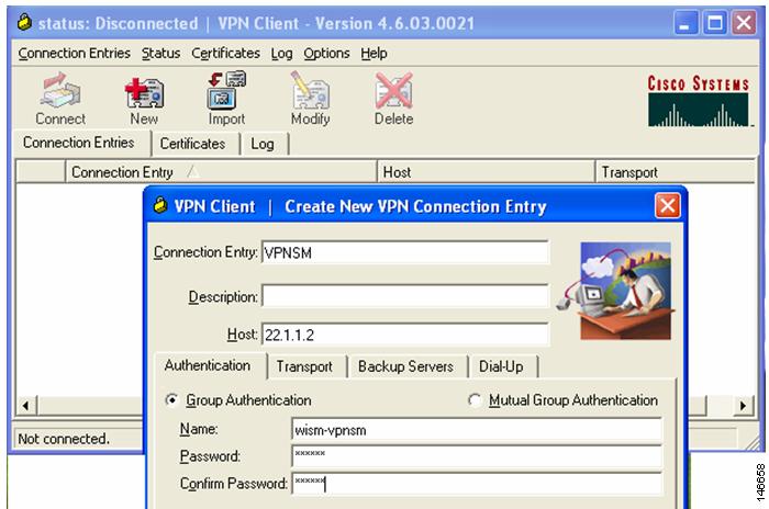
After the switch side of the VPN configuration is done, the VPN client must be configured as follows.
Step 1
Step 2
Figure 43 Create New VPN Connection Entry
Step 3
Step 4
Step 5
Step 6
The profile is now defined, and you can initiate a VPN connection with the VPNSM.
To initiate the connection, choose the connection entry just defined from the main window and click Connect.
When the VPN process is initiated, the EZ-VPN client establishes a connection with the VPNSM and initially negotiates a security association. During this phase, a common set of crypto values are agreed upon by both ends. The client is then challenged to enter a username and password to validate access rights.
After successfully logging in, the client sees a lock icon in the Windows system tray located in the bottom right-hand corner of the desktop.
CCDE, CCENT, Cisco Eos, Cisco Lumin, Cisco Nexus, Cisco StadiumVision, Cisco TelePresence, Cisco WebEx, the Cisco logo, DCE, and Welcome to the Human Network are trademarks; Changing the Way We Work, Live, Play, and Learn and Cisco Store are service marks; and Access Registrar, Aironet, AsyncOS, Bringing the Meeting To You, Catalyst, CCDA, CCDP, CCIE, CCIP, CCNA, CCNP, CCSP, CCVP, Cisco, the Cisco Certified Internetwork Expert logo, Cisco IOS, Cisco Press, Cisco Systems, Cisco Systems Capital, the Cisco Systems logo, Cisco Unity, Collaboration Without Limitation, EtherFast, EtherSwitch, Event Center, Fast Step, Follow Me Browsing, FormShare, GigaDrive, HomeLink, Internet Quotient, IOS, iPhone, iQuick Study, IronPort, the IronPort logo, LightStream, Linksys, MediaTone, MeetingPlace, MeetingPlace Chime Sound, MGX, Networkers, Networking Academy, Network Registrar, PCNow, PIX, PowerPanels, ProConnect, ScriptShare, SenderBase, SMARTnet, Spectrum Expert, StackWise, The Fastest Way to Increase Your Internet Quotient, TransPath, WebEx, and the WebEx logo are registered trademarks of Cisco Systems, Inc. and/or its affiliates in the United States and certain other countries.
All other trademarks mentioned in this document or website are the property of their respective owners. The use of the word partner does not imply a partnership relationship between Cisco and any other company. (0809R)
Copyright © 2009 Cisco Systems, Inc.
All rights reserved.