Feedback
Table Of Contents
GSM-Only Configuration Using Satellite
Configuration Examples
The Cisco MWR 2941-DC supports a variety of topology designs based on various GSM configurations, including the following common topologies:
•
A backhaul interface is used to transfer optimized GSM traffic between RAN-O devices. The traditional backhaul interface is comprised of one or more T1/E1 controllers logically combined to form a multilink connect (except HSDPA, which uses the backhaul interface for T1/E1 line clocking).
•
•
Examples
This appendix includes examples of the following real-world RAN-O configurations:
Note
•
•
•
Note
Asymmetric PWE3 Configuration
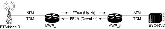
The following example shows an Asymmetric PWE3 configuration (Figure B-1).
Figure B-1 Asymmetric PWE3 Configuration
PE_1
version 12.4service timestamps debug datetime msec localtimeservice timestamps log datetime msec localtimeno service password-encryption!hostname MWR1!boot-start-markerboot-end-marker!card type e1 0 0card type e1 0 1card type e1 0 2card type e1 1 0card type e1 1 1logging buffered 2147483!no aaa new-modelmemory-size iomem 25!network-clock-select 1 E1 1/3!ipran-alt-interrupt tracingmmi polling-interval 60no mmi auto-configureno mmi pvcmmi snmp-timeout 180ip cef!!no ip domain lookupvlan ifdescr detailmultilink bundle-name authenticatedmpls label protocol ldpvpdn enable!!!!!!!!!!!!!!!!!!archivelog config!!controller E1 0/0clock source internalcem-group 1 unframed!controller E1 0/1clock source internalcem-group 20 unframed!controller E1 0/2clock source internalcem-group 12 unframeddescription connected to E1 4/0 of BERT!controller E1 0/3clock source internalcem-group 30 unframed!controller E1 0/4clock source internalcem-group 8 unframed!controller E1 0/5clock source internalcem-group 25 unframed!controller E1 1/0mode aim 1clock source internal!controller E1 1/1mode aim 1clock source internal!controller E1 1/2mode aim 1clock source internal!controller E1 1/3!!pseudowire-class mplsencapsulation mplspreferred-path peer 50.0.0.2!pseudowire-class l2tpencapsulation mplsip protocol udpip local interface Loopback50!!class cem cemclasspayload-size 32!class cem cemclass1dejitter-buffer 400!!!!!!!interface Loopback50ip address 50.0.0.1 255.255.255.255!interface CEM0/0no ip addresscem 1xconnect 50.0.0.2 1 encapsulation mpls!!interface GigabitEthernet0/0ip address 20.0.0.1 255.0.0.0load-interval 30duplex autospeed autompls label protocol ldpmpls ip!interface CEM0/1no ip addresscem 20xconnect 50.0.0.2 2 encapsulation mpls!interface GigabitEthernet0/1ip address 60.0.0.1 255.0.0.0duplex autospeed autompls ip!interface CEM0/2no ip addresscem 12xconnect 50.0.0.2 3 encapsulation mpls!!interface CEM0/3no ip addresscem 30xconnect 50.0.0.2 4 encapsulation mpls!interface CEM0/4no ip addresscem 8xconnect 50.0.0.2 5 encapsulation mpls!!interface CEM0/5no ip addresscem 25xconnect 50.0.0.2 6 encapsulation mpls!!interface ATM0/IMA0no ip addressload-interval 30mcpt-timers 2000 6000 10000no ilmi-keepalivepvc 1/10 l2transportxconnect 50.0.0.2 101 encapsulation mpls!pvc 1/11 l2transportxconnect 50.0.0.2 102 pw-class mpls!pvc 1/21 l2transportencapsulation aal0cell-packing 28 mcpt-timer 2xconnect 50.0.0.2 111 encapsulation mpls!pvc 1/22 l2transportencapsulation aal0cell-packing 18 mcpt-timer 3xconnect 50.0.0.2 112 encapsulation mpls!!interface ATM0/IMA0.1 point-to-pointno snmp trap link-statuspvc 1/12 l2transportxconnect 50.0.0.2 103 encapsulation mpls!!interface ATM0/IMA0.2 multipointno snmp trap link-statuscell-packing 20 mcpt-timer 2xconnect 50.0.0.2 104 pw-class mplspvc 1/13 l2transportencapsulation aal0!pvc 1/14 l2transportencapsulation aal0!!interface ATM0/IMA0.3 point-to-pointno snmp trap link-statuspvc 1/15 l2transportencapsulation aal0cell-packing 10 mcpt-timer 3xconnect 50.0.0.2 105 pw-class mpls!!interface ATM0/IMA0.4 point-to-pointno snmp trap link-statuspvc 1/16 l2transportencapsulation aal0cell-packing 14 mcpt-timer 3xconnect 50.0.0.2 106 pw-class mpls one-to-one!interface ATM0/IMA0.6 multipointno snmp trap link-statuspvc 1/17 l2transportxconnect 50.0.0.2 107 pw-class mpls!pvc 1/18 l2transportencapsulation aal0xconnect 50.0.0.2 108 encapsulation mpls!pvc 1/19 l2transportencapsulation aal0cell-packing 12 mcpt-timer 1xconnect 50.0.0.2 109 encapsulation mpls!!interface ATM1/0no ip addressload-interval 30scrambling-payloadmcpt-timers 1000 5000 10000no ilmi-keepalivepvc 0/5 l2transportencapsulation aal0cell-packing 10 mcpt-timer 3xconnect 50.0.0.2 10 pw-class l2tp!pvc 0/6 l2transportxconnect 50.0.0.2 20 pw-class l2tp!pvc 0/7 l2transportencapsulation aal0cell-packing 28 mcpt-timer 3xconnect 50.0.0.2 30 encapsulation mpls pw-class mpls one-to-one!pvc 0/8 l2transportxconnect 50.0.0.2 40 pw-class mpls!pvc 0/9 l2transportencapsulation aal0xconnect 50.0.0.2 50 pw-class mpls one-to-one!!interface ATM1/0.1 point-to-pointno snmp trap link-statuspvc 0/15 l2transportxconnect 50.0.0.2 13 pw-class mpls!!interface ATM1/0.2 multipointno snmp trap link-statuscell-packing 2 mcpt-timer 1xconnect 50.0.0.2 12 encapsulation mplspvc 0/10 l2transportencapsulation aal0!pvc 0/11 l2transportencapsulation aal0!pvc 0/12 l2transportencapsulation aal0!pvc 0/13 l2transportencapsulation aal0!!interface ATM1/0.3 point-to-pointno snmp trap link-statuspvc 0/16 l2transportencapsulation aal0xconnect 50.0.0.2 14 encapsulation mpls!!interface ATM1/0.4 point-to-pointno snmp trap link-statuspvc 0/17 l2transportencapsulation aal0xconnect 50.0.0.2 15 pw-class mpls one-to-one!!interface ATM1/0.6 multipointno snmp trap link-statuspvc 0/26 l2transportxconnect 50.0.0.2 16 pw-class mpls!pvc 0/27 l2transportencapsulation aal0cell-packing 8 mcpt-timer 3xconnect 50.0.0.2 17 pw-class mpls!pvc 0/28 l2transportencapsulation aal0cell-packing 16 mcpt-timer 2xconnect 50.0.0.2 18 pw-class mpls!!interface ATM1/0.7 multipointno snmp trap link-status!interface ATM1/1no ip addressscrambling-payloadmcpt-timers 1000 5000 10000no ilmi-keepalivecell-packing 20 mcpt-timer 2xconnect 50.0.0.2 11 encapsulation mplspvc 0/21 l2transportencapsulation aal0!pvc 0/22 l2transportencapsulation aal0!pvc 0/23 l2transportencapsulation aal0!!interface ATM1/1.1 point-to-pointno snmp trap link-status!interface ATM1/1.2 multipointno snmp trap link-status!interface ATM1/2no ip addressscrambling-payloadima-group 0no ilmi-keepalive!ip route 9.10.0.254 255.255.255.255 9.11.49.254ip route 30.0.0.0 255.0.0.0 GigabitEthernet0/0ip route 50.0.0.2 255.255.255.255 20.0.0.2ip route 50.0.0.5 255.255.255.255 20.0.0.2!!ip http serverno ip http secure-server!!mpls ldp router-id Loopback50 force!!!!!alias exec cpu show proc cpu | i CPUalias exec hist show proc cpu historyalias exec clc clear countersalias exec cmpls clear mpls counters!line con 0exec-timeout 0 0line aux 0line vty 0 4login!endPE_2
version 12.4service timestamps debug datetime msecservice timestamps log datetime msecno service password-encryption!hostname MWR2!boot-start-markerboot-end-marker!card type e1 0 0card type e1 0 1card type e1 0 2card type e1 1 0card type e1 1 1logging buffered 1000000enable password lab!no aaa new-model!network-clock-select 1 E1 0/0network-clock-select 2 E1 0/1network-clock-select 3 E1 0/2network-clock-select 4 E1 0/3network-clock-select 5 E1 0/4network-clock-select 6 E1 0/5ipran-alt-interrupt tracingmmi polling-interval 60no mmi auto-configureno mmi pvcmmi snmp-timeout 180ip cef!!no ip domain lookupvlan ifdescr detailmultilink bundle-name authenticatedmpls label protocol ldpvpdn enable!!!!!!!!!!!!!!!!!!archivelog config!!controller E1 0/0cem-group 1 unframed!controller E1 0/1cem-group 20 unframed!controller E1 0/2cem-group 12 unframed!controller E1 0/3cem-group 30 unframed!controller E1 0/4cem-group 8 unframed!controller E1 0/5cem-group 25 unframed!controller E1 1/0mode aim 1clock source internal!controller E1 1/1mode aim 1clock source internal!controller E1 1/2mode aim 1clock source internal!controller E1 1/3clock source internal!pseudowire-class mplsencapsulation mplspreferred-path peer 50.0.0.1!pseudowire-class l2tpencapsulation l2tpv3ip protocol udpip local interface Loopback50!!class cem test!class cem cemclasspayload-size 32!!!!!!!interface Loopback50ip address 50.0.0.2 255.255.255.255!interface CEM0/0no ip addresscem 1xconnect 50.0.0.1 1 encapsulation mpls!!interface GigabitEthernet0/0ip address 30.0.0.1 255.0.0.0duplex autospeed autompls ip!interface CEM0/1no ip addresscem 20xconnect 50.0.0.1 2 encapsulation mpls!!interface GigabitEthernet0/1ip address 70.0.0.1 255.0.0.0duplex autospeed autompls ip!interface CEM0/2no ip addresscem 12xconnect 50.0.0.1 3 encapsulation mpls!!interface CEM0/3no ip addresscem 30xconnect 50.0.0.1 4 encapsulation mpls!!interface CEM0/4no ip addresscem 8xconnect 50.0.0.1 5 encapsulation mpls!!interface CEM0/5no ip addresscem 25xconnect 50.0.0.1 6 encapsulation mpls!!interface ATM0/IMA0no ip addressload-interval 30mcpt-timers 2000 6000 10000no ilmi-keepalivepvc 1/10 l2transportxconnect 50.0.0.1 101 encapsulation mpls!pvc 1/11 l2transportxconnect 50.0.0.1 102 pw-class mpls!pvc 1/21 l2transportencapsulation aal0xconnect 50.0.0.1 111 encapsulation mpls!pvc 1/22 l2transportencapsulation aal0xconnect 50.0.0.1 112 encapsulation mpls!!interface ATM0/IMA0.1 point-to-pointno snmp trap link-statuspvc 1/12 l2transportxconnect 50.0.0.1 103 encapsulation mpls!!interface ATM0/IMA0.2 multipointno snmp trap link-statuscell-packing 15 mcpt-timer 3xconnect 50.0.0.1 104 pw-class mplspvc 1/13 l2transportencapsulation aal0!pvc 1/14 l2transportencapsulation aal0!!interface ATM0/IMA0.3 point-to-pointno snmp trap link-statuspvc 1/15 l2transportencapsulation aal0xconnect 50.0.0.1 105 pw-class mpls!!interface ATM0/IMA0.4 point-to-pointno snmp trap link-statuspvc 1/16 l2transportencapsulation aal0cell-packing 7 mcpt-timer 2xconnect 50.0.0.1 106 pw-class mpls one-to-one!!interface ATM0/IMA0.6 multipointno snmp trap link-statuspvc 1/17 l2transportxconnect 50.0.0.1 107 pw-class mpls!pvc 1/18 l2transportencapsulation aal0xconnect 50.0.0.1 108 encapsulation mpls!pvc 1/19 l2transportencapsulation aal0cell-packing 9 mcpt-timer 3xconnect 50.0.0.1 109 encapsulation mpls!!interface ATM1/0ip address 1.1.1.2 255.0.0.0load-interval 30scrambling-payloadmcpt-timers 1000 5000 10000no ilmi-keepalivepvc 0/5 l2transportencapsulation aal0cell-packing 25 mcpt-timer 3xconnect 50.0.0.1 10 pw-class l2tp!pvc 0/6 l2transportxconnect 50.0.0.1 20 pw-class l2tp!pvc 0/7 l2transportencapsulation aal0cell-packing 12 mcpt-timer 2xconnect 50.0.0.1 30 encapsulation mpls pw-class mpls one-to-one!pvc 0/8 l2transportxconnect 50.0.0.1 40 pw-class mpls!pvc 0/9 l2transportencapsulation aal0xconnect 50.0.0.1 50 pw-class mpls one-to-one!pvc 0/99protocol ip 1.1.1.1 broadcastencapsulation aal5snap!!interface ATM1/0.1 point-to-pointno snmp trap link-statuspvc 0/15 l2transportxconnect 50.0.0.1 13 pw-class mpls!!interface ATM1/0.2 multipointno snmp trap link-statuscell-packing 10 mcpt-timer 2xconnect 50.0.0.1 12 encapsulation mplspvc 0/10 l2transportencapsulation aal0!pvc 0/11 l2transportencapsulation aal0!pvc 0/12 l2transportencapsulation aal0!pvc 0/13 l2transportencapsulation aal0!!interface ATM1/0.3 point-to-pointno snmp trap link-statuspvc 0/16 l2transportencapsulation aal0xconnect 50.0.0.1 14 encapsulation mpls!!interface ATM1/0.4 point-to-pointno snmp trap link-statuspvc 0/17 l2transportencapsulation aal0xconnect 50.0.0.1 15 pw-class mpls one-to-one!!interface ATM1/0.6 multipointno snmp trap link-statuspvc 0/26 l2transportxconnect 50.0.0.1 16 pw-class mpls!pvc 0/27 l2transportencapsulation aal0cell-packing 18 mcpt-timer 3xconnect 50.0.0.1 17 pw-class mpls!pvc 0/28 l2transportencapsulation aal0cell-packing 24 mcpt-timer 2xconnect 50.0.0.1 18 pw-class mpls!!interface ATM1/0.7 multipointno snmp trap link-status!interface ATM1/1no ip addressscrambling-payloadmcpt-timers 1000 5000 10000no ilmi-keepalivecell-packing 20 mcpt-timer 2xconnect 50.0.0.1 11 encapsulation mplspvc 0/21 l2transportencapsulation aal0!pvc 0/22 l2transportencapsulation aal0!pvc 0/23 l2transportencapsulation aal0!!interface ATM1/2no ip addressscrambling-payloadima-group 0no ilmi-keepalive!ip route 9.10.0.254 255.255.255.255 9.11.49.254ip route 20.0.0.0 255.0.0.0 GigabitEthernet0/0ip route 50.0.0.1 255.255.255.255 70.0.0.2ip route 50.0.0.5 255.255.255.255 70.0.0.2!!ip http serverno ip http secure-server!!mpls ldp router-id Loopback50 force!!!!!alias exec cpu show proc cpu | i CPUalias exec hist show proc cpu historyalias exec clc clear countersalias exec cmpls clear mpls counters!line con 0exec-timeout 0 0line aux 0line vty 0 4exec-timeout 0 0login!endPWE3 Redundancy Configuration
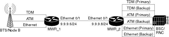
The following example shows a PWE3 Redundancy configuration (Figure B-2).
Figure B-2 PWE3 Redundancy Configuration
MWR_1
version 12.4service timestamps debug datetime msecservice timestamps log datetime msecno service password-encryption!hostname mwr-pe1!boot-start-markerboot-end-marker!card type e1 0 1card type e1 0 2card type e1 1 0card type e1 1 1logging buffered 10000000enable password lab!no aaa new-model!network-clock-select 1 E1 1/2mmi polling-interval 60no mmi auto-configureno mmi pvcmmi snmp-timeout 180ip cef!!!!no ip domain lookupvlan ifdescr detailmultilink bundle-name authenticatedmpls label protocol ldpvpdn enable!archivelog confighidekeys!!controller E1 0/0clock source internalcem-group 0 unframed!controller E1 0/1!controller E1 0/2!controller E1 0/3clock source internal!controller E1 1/0mode aim 1clock source internal!controller E1 1/1!controller E1 1/2!controller E1 1/3clock source internal!interface cem0/0cem 0xconnect 2.2.2.2 1 encapsulation mplsbackup peer 2.2.2.2 2backup delay 20 20!interface ATM1/0no ip addressscrambling-payloadno ilmi-keepalivexconnect 2.2.2.2 3 encapsulation mplsbackup peer 2.2.2.2 4backup delay 20 20pvc 0/1 l2transportencapsulation aal0!interface Loopback0no ip address!interface Loopback1ip address 1.1.1.1 255.255.255.255load-interval 30!interface Loopback101no ip address!!!!interface GigabitEthernet0/0.3encapsulation dot1q 3xconnect 2.2.2.2 5 encapsulation mplsbackup peer 2.2.2.2 6backup delay 20 20!interface GigabitEthernet0/1ip address 9.9.9.6 255.255.255.0load-interval 30speed 100full-duplexmpls ip!!ip forward-protocol ndip route 2.2.2.2 255.255.255.255 9.9.9.8!ip http serverno ip http secure-server!!snmp-server community public RO!!!control-plane!!!!!!!line con 0exec-timeout 0 0logging synchronousline aux 0line vty 0 4exec-timeout 0 0password lablogin!exception data-corruption buffer truncate!endMWR_2
!version 12.4service timestamps debug datetime msecservice timestamps log datetime msecno service password-encryption!hostname mwr-pe2!boot-start-markerboot-end-marker!card type e1 0 0card type e1 0 1card type e1 0 2card type e1 1 0card type e1 1 1logging buffered 10000000enable password lab!no aaa new-model!network-clock-select 1 E1 0/0mmi polling-interval 60no mmi auto-configureno mmi pvcmmi snmp-timeout 180ip arp proxy disableip cef!!!!no ip domain lookupvlan ifdescr detaill2tp-class l2tpmultilink bundle-name authenticatedmpls label protocol ldpmpls ldp session protectionmpls oamecho revision 4vpdn enable!!!!archivelog confighidekeys!!controller E1 0/0cem-group 0 unframed!controller E1 0/1clock source internalcem-group 0 unframed!controller E1 0/2!controller E1 0/3clock source internal!controller E1 0/4clock source internal!controller E1 0/5!controller E1 1/0mode aim 1clock source internal!controller E1 1/1clock source internal!controller E1 1/2clock source internal!controller E1 1/3mode aim 1clock source internal!! Primaryinterface cem0/0cem 0xconnect 1.1.1.1 1 encapsulation mpls!! Backupinterface cem0/1cem 0xconnect 1.1.1.1 2 encapsulation mpls!! Primaryinterface ATM1/0no ip addressscrambling-payloadno ilmi-keepalivexconnect 1.1.1.1 3 encapsulation mplspvc 0/1 l2transportencapsulation aal0!! Backupinterface ATM1/3no ip addressscrambling-payloadno ilmi-keepalivexconnect 1.1.1.1 4 encapsulation mplspvc 0/1 l2transportencapsulation aal0!!interface Loopback1ip address 2.2.2.2 255.255.255.255!! Primaryinterface GigabitEthernet0/0.3encapsulation dot1q 3xconnect 1.1.1.1 5 encapsulation mpls!! Backupinterface GigabitEthernet0/0.4encapsulation dot1q 4xconnect 1.1.1.1 6 encapsulation mpls!!!interface GigabitEthernet0/1ip address 9.9.9.8 255.255.255.0load-interval 30speed 100full-duplexmpls ipno cdp enable!ip forward-protocol ndip route 1.1.1.1 255.255.255.255 9.9.9.6!no ip http serverno ip http secure-server!!snmp-server community private RWsnmp-server community public ROsnmp-server ifindex persistsnmp-server trap link ietfno snmp-server sparse-tablessnmp-server queue-length 100snmp-server enable traps snmp authentication linkdown linkup coldstart warmstartsnmp-server enable traps ipranno cdp runroute-map test permit 10match mpls-label!!!mpls ldp router-id Loopback1 force!control-plane!no call rsvp-sync!!!line con 0exec-timeout 0 0logging synchronousline aux 0line vty 0 4exec-timeout 0 0password lablogin!exception data-corruption buffer truncate!endTDM over MPLS Configuration
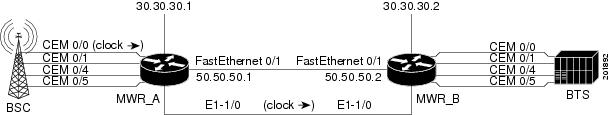
Figure B-3 shows a TDM over MPLS configuration. The configuration uses both SAToP and CESoPSN for E1 and T1.
Figure B-3 TDM over MPLS Configuration
MWR_A
!version 12.4service timestamps debug datetime msec localtime show-timezoneservice timestamps log datetime msec localtime show-timezoneno service password-encryptionservice internal!hostname mwr_A!boot-start-markerboot-end-marker!card type e1 0 0card type t1 0 2enable password xxx!no aaa new-modelclock timezone est -5!network-clock-select 1 E1 0/0mmi polling-interval 60no mmi auto-configureno mmi pvcmmi snmp-timeout 180ip cef!controller E1 0/0cem-group 0 timeslots 1-31description E1 CESoPSN example!controller E1 0/1clock source internalcem-group 1 unframeddescription E1 SATOP example!controller T1 0/4framing esfclock source internallinecode b8zscem-group 4 unframeddescription T1 SATOP example!controller T1 0/5framing esfclock source internallinecode b8zscem-group 5 timeslots 1-24description T1 CESoPSN example!controller E1 1/0clock source internal!controller E1 1/1!interface Loopback0ip address 30.30.30.1 255.255.255.255!interface CEM0/0no ip addresscem 0xconnect 30.30.30.2 300 encapsulation mpls!!interface GigabitEthernet0/0duplex autospeed autono cdp enable!interface CEM0/1no ip addresscem 1xconnect 30.30.30.2 301 encapsulation mpls!!interface GigabitEthernet0/1ip address 50.50.50.1 255.255.255.0duplex autospeed autompls ipno cdp enable!interface CEM0/4no ip addresscem 4xconnect 30.30.30.2 304 encapsulation mpls!!interface CEM0/5no ip addresscem 5xconnect 30.30.30.2 305 encapsulation mpls!!no ip classlessip route 30.30.30.2 255.255.255.255 50.50.50.2!no ip http serverno ip http secure-server!line con 0password xxxloginline aux 0password xxxloginno execline vty 0 4password xxxlogin!endMWR_B
!version 12.4service timestamps debug datetime msec localtime show-timezoneservice timestamps log datetime msec localtime show-timezoneno service password-encryptionservice internal!hostname mwr_B!boot-start-markerboot-end-marker!card type e1 0 0card type t1 0 2enable password xxx!no aaa new-modelclock timezone est -5!network-clock-select 1 E1 1/0mmi polling-interval 60no mmi auto-configureno mmi pvcmmi snmp-timeout 180ip cef!controller E1 0/0clock source internalcem-group 0 timeslots 1-31description E1 CESoPSN example!controller E1 0/1clock source internalcem-group 1 unframeddescription E1 SATOP example!controller T1 0/4framing esfclock source internallinecode b8zscem-group 4 unframeddescription T1 SATOP example!controller T1 0/5framing esfclock source internallinecode b8zscem-group 5 timeslots 1-24description T1 CESoPSN example!controller E1 1/0!controller E1 1/1!interface Loopback0ip address 30.30.30.2 255.255.255.255!interface CEM0/0no ip addresscem 0xconnect 30.30.30.1 300 encapsulation mpls!!interface GigabitEthernet0/0duplex autospeed autono cdp enable!interface CEM0/1no ip addresscem 1xconnect 30.30.30.1 301 encapsulation mpls!!interface GigabitEthernet0/1ip address 50.50.50.2 255.255.255.0duplex autospeed autompls ipno cdp enable!interface CEM0/4no ip addresscem 4xconnect 30.30.30.1 304 encapsulation mpls!!interface CEM0/5no ip addresscem 5xconnect 30.30.30.1 305 encapsulation mpls!!no ip classlessip route 30.30.30.2 255.255.255.255 50.50.50.1!no ip http serverno ip http secure-server!line con 0password xxxloginline aux 0password xxxloginno execline vty 0 4password xxxlogin!endATM over MPLS Configuration
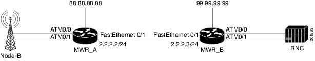
This example shows how to accomplish the following configurations (Figure B-4):
•
•
•
•
•
•
•
•
Figure B-4 ATM over MPLS Configuration
MWR_A
!version 12.4service timestamps debug datetime msecservice timestamps log datetime msecno service password-encryption!hostname mwr_A!boot-start-markerboot-end-marker!card type e1 0 0card type e1 0 1card type e1 0 2card type e1 1 0logging buffered 4096enable password lab!no aaa new-modelmemory-size iomem 25!network-clock-select 1 E1 1/0mmi polling-interval 60no mmi auto-configureno mmi pvcmmi snmp-timeout 180ip cef!!no ip domain lookupip domain name cisco.commultilink bundle-name authenticatedmpls label range 100 100000 static 16 99vpdn enable!!!!!!!!!!!!!!!!!!archivelog config!!controller E1 0/0mode aim 1clock source internal!controller E1 0/1mode aim 1clock source internal!controller E1 0/2mode aim 1clock source internal!controller E1 0/3mode aim 1clock source internal!controller E1 0/4!controller E1 0/5!controller E1 1/0!controller E1 1/1!pseudowire-class mpls-exp-5encapsulation mplsmpls experimental 5!!!!!!!!interface Loopback0ip address 88.88.88.88 255.255.255.255!interface ATM0/0no ip addressscrambling-payloadmcpt-timers 1000 2000 3000no ilmi-keepalivecell-packing 28 mcpt-timer 3xconnect 99.99.99.99 100 encapsulation mplspvc 1/35 l2transportencapsulation aal0!pvc 1/36 l2transportencapsulation aal0!pvc 1/37 l2transportencapsulation aal0!!interface GigabitEthernet0/0ip address 172.18.52.129 255.255.255.0duplex autospeed autono keepalive!interface ATM0/1no ip addressload-interval 30scrambling-payloadmcpt-timers 1000 2000 3000no ilmi-keepalivepvc 0/10!pvc 0/100 l2transportencapsulation aal5xconnect 99.99.99.99 1100 encapsulation mpls!pvc 0/101 l2transportencapsulation aal0cell-packing 28 mcpt-timer 3xconnect 99.99.99.99 1101 encapsulation mpls!pvc 0/102 l2transportencapsulation aal0cell-packing 28 mcpt-timer 3xconnect 99.99.99.99 1102 encapsulation mpls!pvc 0/103 l2transportencapsulation aal0cell-packing 28 mcpt-timer 3xconnect 99.99.99.99 1103 pw-class mpls-exp-5!!interface ATM0/1.1 multipointno snmp trap link-statuscell-packing 28 mcpt-timer 3xconnect 99.99.99.99 1200 encapsulation mplspvc 1/35 l2transportencapsulation aal0pw-pvc 2/135!pvc 1/36 l2transportencapsulation aal0pw-pvc 2/136!pvc 1/37 l2transportencapsulation aal0pw-pvc 2/137!!interface GigabitEthernet0/1description interface to 7600 fas 3/5ip address 2.2.2.2 255.255.255.0duplex autospeed autompls ipno keepalive!interface ATM0/2no ip addressscrambling-payloadno ilmi-keepalive!interface ATM0/3no ip addressscrambling-payloadno ilmi-keepalive!interface ATM0/IMA1no ip addressno ilmi-keepalive!ip route 0.0.0.0 0.0.0.0 172.18.52.1ip route 99.99.99.99 255.255.255.255 2.2.2.3!!ip http serverno ip http secure-server!!mpls ldp router-id Loopback0disable-eadi!!!!line con 0exec-timeout 0 0line aux 0line vty 0 4exec-timeout 0 0privilege level 15password labno login!endMWR_B
!version 12.4service timestamps debug datetime msecservice timestamps log datetime msecno service password-encryption!hostname mwr_B!boot-start-markerboot-end-marker!card type e1 0 0card type e1 0 1logging buffered 4096enable password lab!no aaa new-model!network-clock-select 1 E1 0/0mmi polling-interval 60no mmi auto-configureno mmi pvcmmi snmp-timeout 180ip cef!!no ip domain lookupip domain name cisco.commultilink bundle-name authenticatedmpls label protocol ldpvpdn enable!!!!!!!!!!!!!!!!!!archivelog config!!controller E1 0/0mode aim 1!controller E1 0/1mode aim 1!controller E1 0/2mode aim 1!controller E1 0/3mode aim 1!controller E1 0/4!controller E1 0/5!pseudowire-class mpls-exp-5encapsulation mplsmpls experimental 5!!!!!!!!interface Loopback0ip address 99.99.99.99 255.255.255.255!interface ATM0/0no ip addressscrambling-payloadmcpt-timers 1000 2000 3000no ilmi-keepalivecell-packing 28 mcpt-timer 3xconnect 88.88.88.88 100 encapsulation mplspvc 1/35 l2transportencapsulation aal0!pvc 1/36 l2transportencapsulation aal0!pvc 1/37 l2transportencapsulation aal0!!interface GigabitEthernet0/0ip address 172.18.52.130 255.255.255.0duplex autospeed autokeepalive 1!interface ATM0/1no ip addressscrambling-payloadmcpt-timers 1000 2000 3000no ilmi-keepalivepvc 0/2!pvc 0/100 l2transportencapsulation aal5xconnect 88.88.88.88 1100 encapsulation mpls!pvc 0/101 l2transportencapsulation aal0cell-packing 28 mcpt-timer 3xconnect 88.88.88.88 1101 encapsulation mpls!pvc 0/102 l2transportencapsulation aal0cell-packing 28 mcpt-timer 3xconnect 88.88.88.88 1102 encapsulation mpls!pvc 0/103 l2transportencapsulation aal0cell-packing 28 mcpt-timer 3xconnect 88.88.88.88 1103 pw-class mpls-exp-5!!interface ATM0/1.1 multipointno snmp trap link-statuscell-packing 28 mcpt-timer 3xconnect 88.88.88.88 1200 encapsulation mplspvc 2/135 l2transportencapsulation aal0!pvc 2/136 l2transportencapsulation aal0!pvc 2/137 l2transportencapsulation aal0!!interface GigabitEthernet0/1ip address 2.2.2.3 255.255.255.0duplex autospeed autompls ip!interface ATM0/2no ip addressscrambling-payloadima-group 0no ilmi-keepalive!interface ATM0/3no ip addressscrambling-payloadima-group 0no ilmi-keepalive!ip route 0.0.0.0 0.0.0.0 172.18.52.1ip route 88.88.88.88 255.255.255.255 2.2.2.2!!ip http serverno ip http secure-server!!mpls ldp router-id Loopback0!!!!!line con 0exec-timeout 0 0line aux 0line vty 0 4exec-timeout 0 0password lablogin!endGSM-Only Configuration
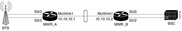
The standard GSM topology includes one or more shorthaul interface connections from the BTS to a Cisco MWR 2941-DC through separate T1/E1 connections. The Cisco MWR 2941-DC routers are connected back-to-back using an MLPPP backhaul connection (two or more T1/E1 connections). At the BSC side, the Cisco MWR 2941-DC-to-BSC connectivity is exactly the same as the BTS-to-Cisco MWR 2941-DC connections. In this example, only GSM traffic traverses the topology (Figure B-5).
Figure B-5 GSM-Only Configuration
MWR_A
!card type E1 0 0card type E1 0 1!network-clock-select 1 E1 0/1!ipran-mib snmp-access inBandipran-mib location cellSite!!controller E1 0/0framing NO-CRC4clock source internalchannel-group 0 timeslots 1-31!controller E1 0/1channel-group 0 timeslots 1-31!controller E1 0/2framing NO-CRC4clock source internalchannel-group 0 timeslots 1-31!!class-map match-any llq-classmatch ip dscp ef!!policy-map llq-policyclass llq-classpriority percent 99class class-defaultbandwidth remaining percent 1queue-limit 45!interface Multilink1ip address 10.10.10.1 255.255.255.252load-interval 30no keepaliveno cdp enableppp pfc local requestppp pfc remote applyppp acfc local requestppp acfc remote applyppp multilinkppp multilink interleaveppp multilink group 1ppp multilink fragment delay 0 1ppp multilink multiclassmax-reserved-bandwidth 100service-policy output llq-policyhold-queue 50 outip rtp header-compression ietf-format!!interface Serial0/0:0no ip addressencapsulation gsm-abisgsm-abis local 10.10.10.1 4444gsm-abis remote 10.10.10.2 4444gsm-abis set dscp efno keepalive!interface Serial0/1:0no ip addressencapsulation pppkeepalive 1ppp multilink group 1max-reserved-bandwidth 100!interface Serial0/2:0no ip addressencapsulation gsm-abisgsm-abis local 10.10.10.1 4446gsm-abis remote 10.10.10.2 4446gsm-abis set dscp efno keepalive!logging history size 500logging history debugginglogging trap warningssnmp-server community public ROsnmp-server queue-length 100snmp-server enable traps snmp linkdown linkup coldstart warmstartsnmp-server enable traps ipransnmp-server enable traps syslogsnmp-server trap link ietfsnmp-server ifIndex persistno snmp-server sparse-tablesnmp-server host 64.50.100.254 version 2c V2Cdisable-eadiMWR_B
!card type E1 0 0card type E1 0 1!network-clock-select 1 E1 0/0network-clock-select 2 E1 0/2!ipran-mib snmp-access outOfBandipran-mib location aggSite!!controller E1 0/0framing NO-CRC4channel-group 0 timeslots 1-31!controller E1 0/1clock source internalchannel-group 0 timeslots 1-31!controller E1 0/2framing NO-CRC4channel-group 0 timeslots 1-31!!class-map match-any llq-classmatch ip dscp ef!!policy-map llq-policyclass llq-classpriority percent 99class class-defaultbandwidth remaining percent 1queue-limit 45!interface Multilink1ip address 10.10.10.2 255.255.255.252load-interval 30no keepaliveno cdp enableppp pfc local requestppp pfc remote applyppp acfc local requestppp acfc remote applyppp multilinkppp multilink interleaveppp multilink group 1ppp multilink fragment delay 0 1ppp multilink multiclassmax-reserved-bandwidth 100service-policy output llq-policyhold-queue 50 outip rtp header-compression ietf-format!!interface Serial0/0:0no ip addressencapsulation gsm-abisgsm-abis local 10.10.10.2 4444gsm-abis remote 10.10.10.1 4444gsm-abis set dscp efno keepalive!interface Serial0/1:0no ip addressencapsulation pppkeepalive 1ppp multilink group 1max-reserved-bandwidth 100!interface Serial0/2:0no ip addressencapsulation gsm-abisgsm-abis local 10.10.10.2 4446gsm-abis remote 10.10.10.1 4446gsm-abis set dscp efno keepalive!logging history size 500logging history debugginglogging trap warningssnmp-server community public ROsnmp-server queue-length 100snmp-server enable traps snmp linkdown linkup coldstart warmstartsnmp-server enable traps ipransnmp-server enable traps syslogsnmp-server trap link ietfsnmp-server ifIndex persistno snmp-server sparse-tablesnmp-server host 64.50.100.254 version 2c V2Cdisable-eadiGSM-Only Configuration Using Satellite
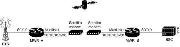
The GSM-only using satellite configuration allows for point-to-point network optimization (Figure B-6).
Figure B-6 GSM-Only Configuration Using Satellite
MWR_A
!card type E1 0 0!network-clock-select 1 E1 0/1!ipran-mib snmp-access inBandipran-mib location cellSite!!controller E1 0/0framing NO-CRC4clock source internalchannel-group 0 timeslots 1-20!controller E1 0/1channel-group 0 timeslots 1-20!!class-map match-any llq-classmatch ip dscp ef!!policy-map llq-policyclass llq-classpriority percent 99class class-defaultbandwidth remaining percent 1queue-limit 45!interface Multilink1ip address 10.10.10.1 255.255.255.252load-interval 30no keepaliveno cdp enableppp pfc local requestppp pfc remote applyppp acfc local requestppp acfc remote applyppp multilinkppp multilink interleaveppp multilink group 1ppp multilink fragment delay 0 1ppp multilink multiclassmax-reserved-bandwidth 100service-policy output llq-policyhold-queue 50 outip rtp header-compression ietf-format!!interface Serial0/0:0no ip addressencapsulation gsm-abisgsm-abis local 10.10.10.1 4444gsm-abis remote 10.10.10.2 4444gsm-abis set dscp efno keepalive!interface Serial0/1:0no ip addressencapsulation pppkeepalive 1ppp multilink group 1max-reserved-bandwidth 100!logging history size 500logging history debugginglogging trap warningssnmp-server community public ROsnmp-server queue-length 100snmp-server enable traps snmp linkdown linkup coldstart warmstartsnmp-server enable traps ipransnmp-server enable traps syslogsnmp-server trap link ietfsnmp-server ifIndex persistno snmp-server sparse-tablesnmp-server host 64.50.100.254 version 2c V2Cdisable-eadiMWR_B
!card type E1 0 0!network-clock-select 1 E1 0/0!ipran-mib snmp-access outOfBandipran-mib location aggSite!!controller E1 0/0framing NO-CRC4channel-group 0 timeslots 1-20!controller E1 0/1clock source internalchannel-group 0 timeslots 1-20!!class-map match-any llq-classmatch ip dscp ef!!policy-map llq-policyclass llq-classpriority percent 99class class-defaultbandwidth remaining percent 1queue-limit 45!interface Multilink1ip address 10.10.10.2 255.255.255.252load-interval 30no keepaliveno cdp enableppp pfc local requestppp pfc remote applyppp acfc local requestppp acfc remote applyppp multilinkppp multilink interleaveppp multilink group 1ppp multilink fragment delay 0 1ppp multilink multiclassmax-reserved-bandwidth 100service-policy output llq-policyhold-queue 50 outip rtp header-compression ietf-format!!interface Serial0/0:0no ip addressencapsulation gsm-abisgsm-abis local 10.10.10.2 4444gsm-abis remote 10.10.10.1 4444gsm-abis set dscp efno keepalive!interface Serial0/1:0no ip addressencapsulation pppkeepalive 1ppp multilink group 1max-reserved-bandwidth 100!logging history size 500logging history debugginglogging trap warningssnmp-server community public ROsnmp-server queue-length 100snmp-server enable traps snmp linkdown linkup coldstart warmstartsnmp-server enable traps ipransnmp-server enable traps syslogsnmp-server trap link ietfsnmp-server ifIndex persistno snmp-server sparse-tablesnmp-server host 64.50.100.254 version 2c V2Cdisable-eadiGSM Congestion Management
These examples show how to configure GSM congestion management for the BTS side and the BSC side.
BTS side
interface Serial0/0:0no ip addressencapsulation gsm-abisgsm-abis local 10.10.10.1 4444gsm-abis remote 10.10.10.2 4444gsm-abis congestion enablegsm-abis congestion critical 1-10gsm-abis congestion critical 31gsm-abis set dscp efno keepaliveBSC side
interface Serial0/0:0no ip addressencapsulation gsm-abisgsm-abis local 10.10.10.2 4444gsm-abis remote 10.10.10.1 4444gsm-abis congestion enablegsm-abis congestion critical 1-10gsm-abis congestion critical 31gsm-abis set dscp efno keepalive