Feedback Feedback
|
Table Of Contents
Release Notes for Cisco Wireless LAN Controllers and Mesh Access Points for Release 4.1.190.5
Cisco Aironet 1520 Access Point (NEW)
Upgrading to this Software Release
Upgrade Path to Release 4.1.190.5
Mandatory Boot Variable Update for Networks with 1520s
Battery Charge Information is not Available for AP1510s with Power Supply 1.01d Firmware
Monitoring Port LED Status on an AP1520
AP1520 Support for Four Gigabit Ethernet Ports
Parent Selection Differences Between AP1520 and AP1510
Controller GUI and CLI Changes
AP1520 Support for Four Gigabit Ethernet Ports
Obtaining Documentation, Support, and Security Guidelines
Printed in the USA on recycled paper containing 10% postconsumer waste.
Release Notes for Cisco Wireless LAN Controllers and Mesh Access Points for Release 4.1.190.5
Last revised: April 09, 2009These release notes describe features, enhancements, and caveats in Release 4.1.190.5 and IOS version AP 12.4(3g)JMA1.
Release 4.1.190.5 is supported on the following Cisco Wireless LAN controller platforms: 2100 series, 4400 series and Wireless Service Module (WiSM) for the Catalyst 6500; and is compatible with the Cisco Wireless Control System (WCS), Release 4.1 and greater.
Release 4.1.190.5 is compatible with Release 4.1.91.0 of the Cisco Wireless Control System (WCS).
Release 4.1.190.5 supports the following outdoor mesh access points:
•
Cisco Aironet 1500 Series (AP1505, AP1510, AP1520)
Note
Caution
Caution
Note
•
•
Note
Note
Contents
These release notes contain the following sections:
•
•
Overview of Features
Release 4.1.190.5 provides extended wireless mesh features beyond that offered in the main Cisco Unified Wireless Network (CUWN) release base. From this release on, mesh-specific features will only be available in the mesh release series until it is merged back into the main CUWN sequence at a future date.
Note
Although a controller installed with Release 4.1.190.5 does not support configuration and management of indoor (standard) access points (1000, 1100, 1130, 1200, 1230, 1240 and 1300 series), it does support interoperability of outdoor mesh access points with indoor access points and client roaming between indoor and outdoor access points, when the indoor access points are associated with a separate controller. Additionally, any controller dedicated to indoor access points must have software that supports the relevant indoor access points.
A single interface, Cisco WCS, is available for configuration and management of those controllers that manage indoor and outdoor access points separately.
RAP versus MAP Functionality
Access points within a mesh network operate as either a root access point (RAP) or a mesh access point (MAP). All AP1500 (AP1505, AP1510, AP1520) outdoor access points are by default configured as MAPs. At least one access point within a mesh network must be configured to function as a RAP.
Note
RAPs within the network have a wired connection to the controller and MAPs communicate among themselves and back to the RAP using wireless connections over the backhaul. MAPs use the AWPP protocol to determine the best path through the other mesh access points to the controller. All the possible paths between the MAPs and RAPs form the wireless mesh that is used to carry traffic from wireless LAN clients connected to MAPs and to carry traffic from devices connected to MAP Ethernet ports.
Table 1 details interoperability of AP1505, AP1510 and AP1520 in Release 4.1.190.5.
Hardware Features
Release 4.1.190.5 supports the following outdoor wireless access points:
•
•
•
Table 2 Hardware Features by Platform
2.4 GHz Band
X
X
X
4.9 GHz Band
-
X
X
5.47 GHz Band
-
X1
-
5.8 GHz Band
-
X2
X
DOCSIS 2.0 Cable Modem (Optional)
-
-
X
Fiber Module (Optional)
-
-
X
External Battery Status
X
X
-
Internal Battery Status
-
-
X
LED Indicator3
X
X
X
1 The 5.47 GHz band is used by the -E and -K regulatory domains.
2 The 5.8 GHz band is used by the -A, -C, -N and -S regulatory domains.
3 A detachable, removable Cisco LED indicator is available to detect power for the AP1505 and AP1510.
Cisco Aironet 1520 Access Point (NEW)
The Cisco Aironet 1520 like the AP1505 and AP1510 employs Cisco's Adaptive Wireless Path Protocol (AWPP) to form a dynamic wireless mesh network among mesh access points, and wireless access to any Wi-Fi-compliant client device.
The Cisco Aironet 1520 series lightweight outdoor mesh access point has a dual-radio configuration (802.11a and 802.11b/g). Communication between the outdoor mesh access points (MAPs) is over the 802.11a radio backhaul. Client traffic is generally transmitted over the 802.11b/g radio.
•
•
Key Features on the Cisco Aironet 1520 series include:
•
•
•
–
–
–
–
•
•
Software Features
A summary of the software features supported by each access point is provided in Table 3.
Table 3 Cisco AP 1500 Series Feature Support Matrix for 4.1.190.5
Mesh Network Functionality
Passive scanning-Access point searches for an alternative parent on its current backhaul.
X
X
X
Background Scanning-Access point searches for an alternative parent on any possible backhaul channel.
X
X
-
Optimal Parent Selection-Access point joins the best available parent.
X
X
X
Exclusion Listing-Access point avoids selecting as parent those access points which have a pattern of failing.
X
X
X
Radar-free Coordinated Sector-Access point notifies parent when radar is detected on the channel so an alternative channel can be employed by the sector.
X
X
-1
Dynamic Frequency Selection-Alternative channel is selected when radar is detected in regulated bands.
-
-
-1
Synchronized Channel Change-Parent advises children of intended channel change.
X
X
-
Reliable Link Layer, Extended Retries-Transmissions that do not succeed will extend the number of retry attempts in an effort to improve reliability.
X
X
X
Reliable Link Layer, Secondary Backhaul Radio-A secondary backhaul radio is utilized as a temporary path for traffic that cannot be sent on the primary backhaul due to intermittent interference.
-
X
-
Passive Beaconing-Log messages from an access point that cannot connect are relayed through other access points to the controller.
X
X
-
Network Services Functionality
Ethernet Bridging-Traffic is bridged from hosts connected to a wired port.
X
X
X
Containment of Bridged Multicast Traffic-Multicast traffic (e.g. video camera broadcasts) from a MAP Ethernet port is contained on a RAP Ethernet network and no forwarding occurs (In mode Multicast). This ensures that: (1) Non-LWAPP multicasts received by the RAP are not transmitted back to the MAP Ethernet networks within the mesh network (their point of origin). (2) MAP-to-MAP multicasts do not occur because they are filtered out.
X
X
-
Universal Access-Radio used for backhaul traffic provides access for client traffic
X
X
-
Support for Workgroup Bridges-Allows multiple wired hosts to connect to the wireless network through a workgroup bridge.
X
X
-
Multiple Queues for Backhaul Traffic-Extends client traffic prioritization to the backhaul traffic.
X
X
X
Static Call Admission Control (CAC)-Ensures sufficient bandwidth is available in a mesh sector before serving new T-SPEC client call requests.
-
X
-
Mesh Security
EAP Authentication-Restricts mesh node access to approved, authenticated access points. EAP-FAST authentication provides secure authentication and encryption key management.
X
X
X
Applications
High-speed Roaming-Roam speeds of up to 70 mph are supported for Cisco Compatible Extension v4 clients.
-
X
-
Location-Client location is identified by closest access point.
X
X
-
1 The AP1520 is only supported in the US in Release 4.1.190.5.
Software Images
Table 4 lists the names of the images associated with this release.
System Requirements
You can install this software release on the following Cisco Wireless LAN controller platforms: 2100 series, 4400 series and Wireless Service Module (WiSM) for the Catalyst 6500.
Release 4.1.190.5 is the first standalone mesh release for controllers.
Note
–
•
–
–
–
•
Compatibility Matrix
Table 5 outlines compatibility of controller non-mesh releases with controller mesh releases and indicates the intermediate software releases required as part of the upgrade path. A summary of upgrade path requirements is noted in the "Upgrading to this Software Release" section.
Table 5 Compatibility Matrix for Controller Mesh and Non-Mesh Releases
4.1.190.5
4.0.217.0
4.0.216.0
4.1.190.5
-
4.1.185.0
Y1
-
4.1.181.0
Y1
Y1
4.1.171.0
Y1
Y1
-
4.0.219.0
Y1
Y1
-
4.0.217.204
Y1
Y1
Y1
-
4.0.217.0
Y1
Y1
Y1
Y2
-
4.0.216.0
Y1
Y1
Y1
Y2
Y
-
4.0.206.0
Y1
Y1
Y1
Y2
Y
-
4.0.179.11
Y
Y3
-
4.0.179.8
Y
Y3
Y
-
4.0.155.5
Y
Y3
Y
Y
-
4.0.155.0
Y
Y3
Y
Y
Y
-
3.2.195.10
Y
Y3
Y
Y
Y
-
3.2.193.5
Y
Y3
Y
Y
Y
Y
-
3.2.171.6
Y
Y3
Y
Y
Y
Y
-
3.2.171.5
Y
Y3
Y
Y
Y
Y
Y
-
3.2.150.10
Y
Y3
Y
Y
Y
Y
Y
-
3.2.150.6
Y
Y3
Y
Y
Y
Y
Y
Y
-
3.2.116.21
Y
Y3
Y
Y
Y
Y
Y
Y
-
3.2.78.0
Y
Y3
Y
Y
Y
Y
Y
Y
Y
-
3.1.111.0
Y
Y
Y
Y
Y
-
3.1.105.0
Y
Y
Y
Y
Y
Y
-
3.1.59.24
Y
Y
Y
Y
Y
Y
Y
-
1 CUSTOMERS THAT REQUIRE DYNAMIC FREQUENCY SELECTION (DFS) FUNCTIONALITY SHOULD NOT USE THIS RELEASE. This release does not provide DFS functionality fixes found in release 4.0.217.204. Additionally, this release is not supported in ETSI compliant countries or Singapore.
2 Release 4.0.217.204 provides fixes for DFS. This functionality is only needed in countries where DFS rules apply.
3 An upgrade to 4.0.206.0 is not allowed in the following Country Codes when operating with the following access points: Australia (1505 and 1510), Brazil (1505 and 1510), Hong Kong (1505 and 1510), India (1505 and 1510), Japan (1510), Korea (1505 and 1510), Mexico (1505 and 1510), New Zealand (1505 and 1510), and Russia (1505 and 1510).
Upgrading to this Software Release
For instructions on downloading software to the controller using either Cisco WCS or the controller GUI or CLI, refer to the release 4.1 versions of the Cisco Wireless Control System Configuration Guide and the Cisco Wireless LAN Controller Configuration Guide.
Click this link to access those documents:
http://www.cisco.com/en/US/products/hw/wireless/tsd_products_support_category_home.html
Upgrade Path to Release 4.1.190.5
Details for upgrading your network to Release 4.1.190.5 from earlier releases of 3.1, 3.2, 4.0 and 4.1 are described below.
•
•
–
–
–
•
–
–
–
–
Mandatory Boot Variable Update for Networks with 1520s
If your network is operating with 1520s or you plan to install 1520s in your network, you must set the boot variable on the 1520 BEFORE upgrading from release 4.1.190.5 to 4.1.191.24M (or greater mesh release). Updating the boot variable ensures the 1520 joins correctly.
Note
•
–
•
Checking the Boot Variable Setting
To check the setting of the boot variable, do the following:
Step 1
debug ap enable AP_Name
debug ap command "more flash:/env_vars" Cisco_AP
A display similar to the following appears:
Tue Jan 15 00:00:15 2009: SLT-HCAB-MAP-01-fe.bb.6f: 5G_RADIO_CARRIER_SET=0020Tue Jan 15 00:00:15 2009: SLT-HCAB-MAP-01-fe.bb.6f: 5G_RADIO_ENCRYPTION_CONFIG=02Tue Jan 15 00:00:15 2009: SLT-HCAB-MAP-01-fe.bb.6f: 5G_RADIO_MAX_TX_POWER=65535Tue Jan 15 00:00:15 2009: SLT-HCAB-MAP-01-fe.bb.6f: BOOT=flash:/c1520-k9w9-mx.124-3g.JMA1/c1520-k9w9-mx.124-3g.JMA1Tue Jan 15 00:00:15 2009: SLT-HCAB-MAP-01-fe.bb.6f: DEFAULT_ROUTER=11.200.9.20Tue Jan 15 00:00:15 2009: SLT-HCAB-MAP-01-fe.bb.6f: DEVIATION_NUM=0Tue Jan 15 00:00:15 2009: SLT-HCAB-MAP-01-fe.bb.6f: DOT11G_RADIO_MODE=255Tue Jan 15 00:00:15 2009: SLT-HCAB-MAP-01-fe.bb.6f: DOT11_DEVICE_TYPE=4CTue Jan 15 00:00:15 2009: SLT-HCAB-MAP-01-fe.bb.6f: DOT11_ENCRYPTION_CONFIG=02Tue Jan 15 00:00:15 2009: SLT-HCAB-MAP-01-fe.bb.6f: DOT11_MAX_ASSOCIATION_NUM=2007Tue Jan 15 00:00:15 2009: SLT-HCAB-MAP-01-fe.bb.6f: ENABLE_BREAK=yesTue Jan 15 00:00:15 2009: SLT-HCAB-MAP-01-fe.bb.6f: FAB_PART_NUM=800-28909-02Tue Jan 15 00:00:15 2009: SLT-HCAB-MAP-01-fe.bb.6f: IP_ADDR=11.200.9.99Tue Jan 15 00:00:15 2009: SLT-HCAB-MAP-01-fe.bb.6f: MAC_ADDR=00:1d:e5:e8:aa:00Tue Jan 15 00:00:15 2009: SLT-HCAB-MAP-01-fe.bb.6f: MAC_ADDR_BLOCK_SIZE=256Tue Jan 15 00:00:15 2009: SLT-HCAB-MAP-01-fe.bb.6f: MANUAL_BOOT=noTue Jan 15 00:00:15 2009: SLT-HCAB-MAP-01-fe.bb.6f: NETMASK=255.255.0.0Tue Jan 15 00:00:15 2009: SLT-HCAB-MAP-01-fe.bb.6f: NEW_IMAGE=yesTue Jan 15 00:00:15 2009: SLT-HCAB-MAP-01-fe.bb.6f: PCA_ASSY_NUM_800=03 20 00 70 ED 02Tue Jan 15 00:00:15 2009: SLT-HCAB-MAP-01-fe.bb.6f: PCA_PART_NUM_73=49 2A A6 02Tue Jan 15 00:00:15 2009: SLT-HCAB-MAP-01-fe.bb.6f: PCA_REVISION_NUM=A0Tue Jan 15 00:00:15 2009: SLT-HCAB-MAP-01-fe.bb.6f: PCA_REVISION_NUM_800=A0Tue Jan 15 00:00:15 2009: SLT-HCAB-MAP-01-fe.bb.6f: PCB_SERIAL_NUM=FHH1101007FTue Jan 15 00:00:15 2009: SLT-HCAB-MAP-01-fe.bb.6f: PEP_PRODUCT_ID=AIR-LAP1521AG-A-K9Tue Jan 15 00:00:15 2009: SLT-HCAB-MAP-01-fe.bb.6f: PEP_VERSION_ID=V01 Tue Jan 15 00:00:15 2009: SLT-HCAB-MAP-01-fe.bb.6f: PRODUCT_MODEL_NUM=AIR-LAP1521AG-A-K9Tue Jan 15 00:00:15 2009: SLT-HCAB-MAP-01-fe.bb.6f: RADIO_CARRIER_SET=00FFTue Jan 15 00:00:15 2009: SLT-HCAB-MAP-01-fe.bb.6f: RADIO_MAX_TX_POWER=65535Tue Jan 15 00:00:15 2009: SLT-HCAB-MAP-01-fe.bb.6f: SYSTEM_REVISION_NUM_800=A0Tue Jan 15 00:00:15 2009: SLT-HCAB-MAP-01-fe.bb.6f: TOP_ASSY_NUM_800=03 20 00 71 22 02Tue Jan 15 00:00:15 2009: SLT-HCAB-MAP-01-fe.bb.6f: TOP_ASSY_SERIAL_NUM=SJC1101007FTue Jan 15 00:00:15 2009: SLT-HCAB-MAP-01-fe.bb.6f: param-any=Step 2
Note
Updating the Boot Variable
To update the boot variable on a 1520 prior to a software upgrade, do the following:
Step 1
debug ap enable AP_Name
debug ap command "debug lwapp con cli" AP_Name
debug ap command "test mesh enable telnet" AP_Name
show ap config general AP_Name
Note
Step 2
telnet IP_address
Step 3
enable
debug lwapp console cli
show version
Look for the system image as noted in the example below:
System image file is "flash:/c1520-k9w9-mx.124-3g.JMA1/c1520-k9w9-mx.124-3g.JMA1"Enter the image name (enclosed within quotes) into the boot system... command below.
config term
boot system flash:/c1520-k9w9-mx.124-3g.JMA1/c1520-k9w9-mx.124-3g.JMA1
Note
exit
Enter the following command to verify you typed the image string correctly.
more flash:/env_vars Cisco_AP
Step 4
Important Notes
This section describes information about changes to the controller CLI and GUI, and operational notes for Release 4.1.190.5.
Operational Notes
The following operational notes are relevant to this release.
Battery Charge Information is not Available for AP1510s with Power Supply 1.01d Firmware
An AP1510 with an Alpha FlexNet MPS30-48C-SL power supply must have firmware version 1.02d or greater to supply information about its remaining charge to the controller and Cisco WCS. Otherwise, the controller and WCS display incorrect battery information.
To upgrade your power supply to 1.02d (or greater) firmware, return the power supply to an Alpha service center (Argus).
> To arrange return of power supply call or email:
> US and Canada: 1 888 GO ARGUS (462-7487), International: 1 604 436 5547
> Email: support@argusdcpower.com
> For additional Alpha service centers, see:
> http://www.alpha.com/Contacts/Service-Centers/
Monitoring Port LED Status on an AP1520
When physically disconnecting a cable from an AP1520, the port LED associated with that connection might remain lit for up to 3 seconds.
AP1520 Support for Four Gigabit Ethernet Ports
The AP1520 supports four Ethernet interfaces (g0-PoE in, g1-PoE out,g2-Cable, g3-Fiber). Refer to the "Controller GUI and CLI Changes" section for details how the CLI and GUI displays are modified to report status on the four Ethernet ports.
Parent Selection Differences Between AP1520 and AP1510
When operating as a MAP, the AP1520 generally prefers to select a parent that shares the same bridge group name (BGN), rather than a wired interface (uplink) to the controller. This approach is different from the AP1510 which always places a higher priority on selecting a parent with a wired connection.
Additionally, when an AP1520 connects to a parent with a default (null) BGN, the AP1520 disables the Ethernet Bridging feature to prevent a potential bridge loop. An AP1510 does not disable Ethernet Bridging.
To ensure smooth operation, configure a bridge group name for the AP1520 and verify that the mesh access point is connecting to a parent on the same bridge group to allow Ethernet bridging.
Controller GUI and CLI Changes
The following changes can be seen in the controller GUI and CLI interfaces.
•
AP1520 Support for Four Gigabit Ethernet Ports
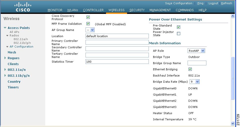
The AP1520 supports four Ethernet interfaces: g0-PoE in, g1-PoE out, g2-Cable and g3-Fiber. Both the controller CLI and GUI show the state for each of the four Gigabit Ethernet ports as noted below.
•
Note
•
•
(controller)>show mesh env summaryAP Name Temperature(C/F) Heater Ethernet Battery-------- --------------- -------- ------- -------rap1242.c9ef N/A N/A UP N/Arap1522.a380 29/84 OFF UpDnDnDn N/Arap1522.4da8 31/87 OFF UpDnDnDn N/Amap1522.4dcc 28/82 OFF DnDnDnDn N/Alap1510.2320 33/91 OFF DOWN N/Amap1522.d4af 29/84 OFF DnDnDnDn N/A•
Figure 1 Wireless > AP1520 > Details
Caveats
This section lists open, resolved and closed caveats in Release 4.1.190.5.
Open Caveats
The following caveats are open (unresolved) in this release:
•
Workaround: Query the information using the controller GUI or CLI, where applicable.
•
Workaround: Select the Tx Power Level Assignment based on the values 1 (high) to 5 (low) and ignore the dBm values associated with those numbers.
•
Workaround: None. This is a display issue only. It is not service affecting.
•
Workaround: None.
•
Workaround: None.
•
Workaround: Verify that the Bridge Group Name (BGN) for the AP1520 joining the network is properly configured to limit the number of potential parents.
•
Additionally, when an AP1520 connects to a parent with a default (null) BGN, the AP1520 disables the Ethernet Bridging feature to prevent a potential bridge loop. This behavior also differs from that of the AP1510.
Workaround: Configure a bridge group name for the AP1520 and verify that its parent is on the same bridge group to allow Ethernet Bridging.
•
Workaround: None.
•
Workaround: Verify that the entered antenna gain is within the FCC limit.
•
Workaround: Always configure and use Bridge Group Names in the network.
•
This is seen when a controller is upgraded from mesh release 4.1.190.5 to 4.1.191.24M and the 1520 has a wireless connection to the controller. It might also happen when a controller is upgraded from 4.1.190.5 to other future mesh releases.
Workaround: To recover from an incomplete 1520 boot up due to a 4.1.190.5 to 4.1.191.24M upgrade, enter the following bootloader commands in the AP console:
delete flash:/update/c1520-k9w9-mx.124-3g.JMB/c1520-k9w9-mx.124-3g.JMBset BOOT flash:/c1520-k9w9-mx.124-3g.JMA/c1520-k9w9-mx.124-3g.JMAbootTo verify the configuration, enter
set
Note
Note
Closed Caveats
•
If You Need More Information
If you need information about a specific caveat that does not appear in these release notes, you can use the Cisco Bug Toolkit to find caveats of any severity. Click this URL to browse to the Bug Toolkit:
http://tools.cisco.com/Support/BugToolKit/
(If you request a defect that cannot be displayed, the defect number might not exist, the defect might not yet have a customer-visible description, or the defect might be marked Cisco Confidential.)
Troubleshooting
For the most up-to-date, detailed troubleshooting information, refer to the Cisco TAC website at:
Click Troubleshooting. Then choose your product and then select the Troubleshoot and Alerts heading on the product page to find information on the problem you are experiencing and other service advisories.
For additional suggestions on troubleshooting mesh networks, refer to the Troubleshooting Mesh Networks document at the following Cisco.com URL:
http://www.cisco.com/en/US/products/ps6548/prod_troubleshooting_guides_list.html
Related Documentation
The following documents are related to mesh networks:
•
•
•
•
•
•
•
•
•
•
•
Note
Obtaining Documentation, Support, and Security Guidelines
For information on obtaining documentation, obtaining support, providing documentation feedback, security guidelines, and also recommended aliases and general Cisco documents, see the monthly What's New in Cisco Product Documentation, which also lists all new and revised Cisco technical documentation, at:
http://www.cisco.com/en/US/docs/general/whatsnew/whatsnew.html
This document is to be used in conjunction with the documents listed in the Related Documents section.
CCDE, CCENT, Cisco Eos, Cisco HealthPresence, the Cisco logo, Cisco Lumin, Cisco Nexus, Cisco StadiumVision, Cisco TelePresence, Cisco WebEx, DCE, and Welcome to the Human Network are trademarks; Changing the Way We Work, Live, Play, and Learn and Cisco Store are service marks; and Access Registrar, Aironet, AsyncOS, Bringing the Meeting To You, Catalyst, CCDA, CCDP, CCIE, CCIP, CCNA, CCNP, CCSP, CCVP, Cisco, the Cisco Certified Internetwork Expert logo, Cisco IOS, Cisco Press, Cisco Systems, Cisco Systems Capital, the Cisco Systems logo, Cisco Unity, Collaboration Without Limitation, EtherFast, EtherSwitch, Event Center, Fast Step, Follow Me Browsing, FormShare, GigaDrive, HomeLink, Internet Quotient, IOS, iPhone, iQuick Study, IronPort, the IronPort logo, LightStream, Linksys, MediaTone, MeetingPlace, MeetingPlace Chime Sound, MGX, Networkers, Networking Academy, Network Registrar, PCNow, PIX, PowerPanels, ProConnect, ScriptShare, SenderBase, SMARTnet, Spectrum Expert, StackWise, The Fastest Way to Increase Your Internet Quotient, TransPath, WebEx, and the WebEx logo are registered trademarks of Cisco Systems, Inc. and/or its affiliates in the United States and certain other countries.
All other trademarks mentioned in this document or website are the property of their respective owners. The use of the word partner does not imply a partnership relationship between Cisco and any other company. (0812R)
Any Internet Protocol (IP) addresses and phone numbers used in this document are not intended to be actual addresses and phone numbers. Any examples, command display output, network topology diagrams, and other figures included in the document are shown for illustrative purposes only.
Any use of actual IP addresses or phone numbers in illustrative content is unintentional and coincidental.
© 2009 Cisco Systems, Inc. All rights reserved.
Printed in the USA on recycled paper containing 10% postconsumer waste.