Feedback Feedback
|
Table Of Contents
Configuring Ethernet Virtual Connections on the Cisco ASR 903 Router
Configuring a Service Instance
Encapsulation Using a VLAN Range
Two Service Instances Joining the Same Bridge Domain
Bridge Domains and VLAN Encapsulation
Configuring Other Features on EFPs
MAC Address Forwarding, Learning and Aging on EFPs
Configuring IEEE 802.1Q Tunneling and Layer 2 Protocol Tunneling Using EFPs
EFPs and Ethernet over Multiprotocol Layer Switching (EoMPLS)
EFPs and Trunk Port MAC Addresses
L3 Unicast and Multicast Routing on a Bridge Domain with Multiple EFPs
Configuring L3 Multicast Routing on a Bridge Domain
Cross-Connect on EFP Interfaces
Configuring Cross-Connect on an EFP Interface
Configuring a Static MAC Address
Configuring a Multicast Static MAC Address
Configuring Ethernet Virtual Connections on the Cisco ASR 903 Router
An Ethernet Virtual Connection (EVC) is defined by the Metro-Ethernet Forum (MEF) as an association between two or more user network interfaces that identifies a point-to-point or multipoint-to-multipoint path within the service provider network. An EVC is a conceptual service pipe within the service provider network. A bridge domain is a local broadcast domain that is VLAN-ID-agnostic. An Ethernet flow point (EFP) service instance is a logical interface that connects a bridge domain to a physical port or to an EtherChannel group.
An EVC broadcast domain is determined by a bridge domain and the EFPs that are connected to it. You can connect multiple EFPs to the same bridge domain on the same physical interface, and each EFP can have its own matching criteria and rewrite operation. An incoming frame is matched against EFP matching criteria on the interface, learned on the matching EFP, and forwarded to one or more EFPs in the bridge domain. If there are no matching EFPs, the frame is dropped.
You can use EFPs to configure VLAN translation. For example, if there are two EFPs egressing the same interface, each EFP can have a different VLAN rewrite operation, which is more flexible than the traditional switchport VLAN translation model.
This document describes how to configure EVC features on the Cisco ASR 903 Series Router.
For detailed information about the commands, see:
•
the Cisco IOS XE 3S Carrier Ethernet Command Reference:
http://www.cisco.com/en/US/docs/ios/cether/command/reference/ce_book.html•
http://www.cisco.com/en/US/docs/ios/mcl/allreleasemcl/all_book.htmlThis chapter includes:
•
Supported EVC Features
•
•
–
–
–
•
•
–
pop 1 removes the outermost tag
pop 2 removes the two outermost tags
pop symmetric adds a tag (or 2 tags for pop 2 symmetric) on egress for a push operation
–
–
•
•
•
•
•
•
•
•
•
•
•
These Layer 2 port-based features can run with EVC configured on the port:
•
•
•
Limitations
The following limitations apply when configuring EVC features on the Cisco ASR 903 Series Router:
•
•
•
•
•
Understanding EVC Features
•
Ethernet Virtual Connections
You use the ethernet evc evc-id global configuration command to create an Ethernet virtual connection (EVC). The evc-id or name is a text string from 1 to 100 bytes. Entering this command puts the device into service configuration mode (config-srv) where you configure all parameters that are common to an EVC.
In this mode you can enter these commands:
•
•
•
•
•
Service Instances and EFPs
Configuring a service instance on a Layer 2 port or EtherChannel creates a pseudoport or Ethernet flow point (EFP) on which you configure EVC features. Each service instance has a unique number per interface, but you can use the same number on different interfaces because service instances on different ports are not related.
If you have defined an EVC by entering the ethernet evc evc-id global configuration command, you can associate the EVC with the service instance (optional). There is no default behavior for a service instance.
Use the service instance number ethernet [name] interface configuration command to create an EFP on a Layer 2 interface or EtherChannel and to enter service instance configuration mode. You use service instance configuration mode to configure all management and control date plane attributes and parameters that apply to the service instance on a per-interface basis.
•
•
When you enter service instance configuration mode, you can configure these options:
•
•
•
•
•
•
•
•
•
•
•
•
Enter the [no] shutdown service-instance configuration mode to shut down or bring up a service instance.
•
Encapsulation
Encapsulation defines the matching criteria that maps a VLAN, a range of VLANs, cost of service (CoS) bits, Ethertype, or a combination of these to a service instance. You configure encapsulation in service instance configuration mode. You must configure one encapsulation command per EFP (service instance).
Use the encapsulation service-instance configuration mode command to set encapsulation criteria. Different types of encapsulations are default, dot1q, priority-tagged and untagged. Supported Ethertypes include ipv4, ipv6, pppoe-all, pppoe-discovery, and pppoe-session.
Encapsulation classification options also include:
•
•
•
•
•
After you have entered an encapsulation method, these keyword options are available in service instance configuration mode:
•
•
If a packet entering or leaving a port does not match any of the encapsulations on that port, the packet is dropped, resulting in filtering on both ingress and egress. The encapsulation must match the packet on the wire to determine filtering criteria. On the wire refers to packets ingressing the router before any rewrites and to packets egressing the router after all rewrites.
Note
Bridge Domains
A service instance must be attached to a bridge domain. Flooding and communication behavior of a bridge domain is similar to that of a VLAN domain. Bridge-domain membership is determined by which service instances have joined it, while VLAN domain membership is determined by the VLAN tag in the packet.
Note
Use the bridge-domain bridge-id service-instance configuration mode command to bind the EFP to a bridge domain instance. The bridge-id is the identifier for the bridge domain instance, an integer from 1 to 4000.
Split-Horizon
The split-horizon feature allows service instances in a bridge domain to join groups. Service instances in the same bridge domain and split-horizon group cannot forward data between each other, but can forward data between other service instances that are in the same bridge domain, but not in the same split-horizon group.
Service instances do not have to be in a split-horizon group. If a service instance does not belong to a group, it can send and receive from all ports within the bridge domain. A service instance cannot join more than one split-horizon group.
Enter the bridge-domain bridge-id split-horizon group group_id service-instance configuration mode command to configure a split-horizon group. The group_id is an integer from 0 to 2. All members of the bridge-domain that are configured with the same group_id are part of the same split-horizon group.EFPs that are not configured with an explicit group_id do not belong to any group.
You can configure no more than 64 service instances per bridge domain. When a bridge domain contains a service instance that is part of a split-horizon group, this decreases the number of service instances allowed to be configured in that split-horizon group. The switch supports up to three split-horizon groups plus the default (no group).
In Table 2, the left column means that a bridge domain belongs to a service instance that is part of the indicated split horizon group. Therefore, if a service instance joins split-horizon group 2, it can have no more than 16 members in split horizon group 2 in the same bridge domain. We recommend that you add split horizon groups in numerical order to maximize the number of service instances that can belong to a group.
Rewrite Operations
You can use the rewrite command to modify packet VLAN tags. You can use this command to emulate traditional 802.1Q tagging, where packets enter a router on the native VLAN and VLAN tagging properties are added on egress. You can also use the rewrite command to facilitate VLAN translation and QinQ.
The Cisco ASR 903 Series Router supports only these rewrite commands.
•
•
•
Enter the rewrite ingress tag pop {1 | 2} symmetric service-instance configuration mode command to specify the encapsulation adjustment to be performed on the frame ingress to the EFP. Entering pop 1 pops (removes) the outermost tag; entering pop 2 removes two outermost tags.
Note
When you enter the symmetric keyword, the egress counterpart performs the inverse action and pushes (adds) the encapsulation VLAN. You can use the symmetric keyword only with ingress rewrites and only when single VLANs are configured in encapsulation. If you configure a list of VLANs or a VLAN range or encapsulation default or encapsulation any, the symmetric keyword is not accepted for rewrite operations.
The router does not support rewrite commands for translate in release 3.7.
Possible translation combinations are 1-to-1, 1-to-2, 2-to-1, and 2-to-2. When forwarding to or from a Layer 2 port, you cannot achieve 2-to2 translation because a Layer 2 port is implicitly defined to be rewrite ingress tag pop 1 symmetric.
The router does not support egress rewrite operations beyond the second VLAN that a packet carries. Because of the egress rewrite limitation, if an EFP has a pop 2 rewrite operation at ingress, no other EFP in the same bridge domain can have a rewrite operation.
Static MAC Addresses
The Cisco ASR 903 Series Router supports multicast static MAC addresses, which allow you to enable multicast at the layer 2 level. You can use multicast static MAC addresses to forward multicast packets to specific EFPs on a network.
For instructions on how to configure static MAC addresses, see Configuring a Static MAC Address.
Layer 2 Protocol Features
The Cisco ASR 903 Series Router supports layer 2 protocol peering, forwarding, and tunneling on CDP, LACP, LLDP, PAGP, STP, UDLD, and VTP traffic. For more information about these features, see:
Configuring EFPs
Default EVC Configuration
No EFPs are configured. No service instances or bridge domains are configured.
Configuration Guidelines
The following guidelines apply when you configure EVCs on the Cisco ASR 903 Series Router.
Note
•
Router (config)# interface gigabitethernet0/0/1Router (config-if)# service instance 22 Ethernet etherRouter (config-if-srv)# encapsulation dot1q 10Router (config-if-srv)# bridge-domain 10•
•
•
•
Creating Service Instances
Beginning in privileged EXEC mode, follow these steps to create an EFP service instance:
Step 1
configure terminal
Enter global configuration mode.
Step 2
interface interface-id
Specify the port to attach to the policy map, and enter interface configuration mode. Valid interfaces are physical ports.
Step 3
service instance number ethernet [name]
Configure an EFP (service instance) and enter service instance configuration) mode.
•
•
Step 4
encapsulation {default | dot1q | priority-tagged | untagged}
Configure encapsulation type for the service instance.
•
•
•
•
Step 5
bridge-domain bridge-id [split-horizon group group-id]
Configure the bridge domain ID. The range is from 1 to 4000.
You can use the split-horizon keyword to configure the port as a member of a split horizon group. The group-id range is from 0 to 2.
Step 6
rewrite ingress tag pop {1 | 2} symmetric
(Optional) Specify that encapsulation modification to occur on packets at ingress.
•
•
•
Step 7
end
Return to privileged EXEC mode.
Step 8
show ethernet service instance
show bridge-domain [n | split-horizon]
Verify your entries.
Step 9
copy running-config startup-config
(Optional) Save your entries in the configuration file.
Use the no forms of the commands to remove the service instance, encapsulation type, or bridge domain or to disable the rewrite operation.
Creating a Trunk EFP
Beginning in privileged EXEC mode, follow these steps to create an EFP service instance:
Step 1
configure terminal
Enter global configuration mode.
Step 2
interface interface-id
Specify the port to attach to the policy map, and enter interface configuration mode. Valid interfaces are physical ports.
Note
Step 3
service instance [trunk] number ethernet
Configure an EFP (service instance) and enter service instance configuration) mode.
•
•
Note
Step 4
encapsulation {default | dot1q | priority-tagged | untagged}
Configure encapsulation type for the service instance.
Note
•
•
•
•
Step 5
bridge-domain bridge-id from-encapsulation
Configures the router to derive bridge domains from the encapsulation VLAN list.
Step 6
rewrite ingress tag pop {1 | 2} symmetric
(Optional) Specify that encapsulation modification to occur on packets at ingress.
•
•
Caution
•
Step 7
end
Return to privileged EXEC mode.
Step 8
show ethernet service instance
show bridge-domain [n | split-horizon]
Verify your entries.
Step 9
copy running-config startup-config
(Optional) Save your entries in the configuration file.
Use the no forms of the commands to remove the service instance, encapsulation type, or bridge domain or to disable the rewrite operation.
Configuration Examples
Configuring a Service Instance
Router (config)#interface gigabitethernet0/0/1Router (config-if)#service instance 22 Ethernet etherRouter (config-if-srv)#encapsulation dot1q 10Router (config-if-srv)#bridge-domain 10Encapsulation Using a VLAN Range
Router (config)#interface gigabitethernet0/0/1Router (config-if)#service instance 22 EthernetRouter (config-if-srv)#encapsulation dot1q 22-44Router (config-if-srv)#bridge-domain 10Two Service Instances Joining the Same Bridge Domain
In this example, service instance 1 on interfaces Gigabit Ethernet 0/0/1 and 0/0/2 can bridge between each other.
Router (Router (config)#interface gigabitethernet0/0/1Router (config-if)#service instance 1 EthernetRouter (config-if-srv)#encapsulation dot1q 10Router (config-if-srv)#bridge-domain 10Router (config)#interface gigabitethernet0/0/2Router (config-if)#service instance 1 EthernetRouter (config-if-srv)#encapsulation dot1q 10Router (config-if-srv)#bridge-domain 10Bridge Domains and VLAN Encapsulation
Unlike VLANs, the bridge-domain number does not need to match the VLAN encapsulation number.
Router (config)#interface gigabitethernet0/0/1Router (config-if)#service instance 1 EthernetRouter (config-if-srv)#encapsulation dot1q 10Router (config-if-srv)#bridge-domain 3000Router (config)#interface gigabitethernet0/0/2Router (config-if)#service instance 1 EthernetRouter (config-if-srv)#encapsulation dot1q 10Router (config-if-srv)#bridge-domain 3000However, when encapsulations do not match in the same bridge domain, traffic cannot be forwarded. In this example, the service instances on Gigabit Ethernet 0/0/1 and 0/0/2 can not forward between each other, since the encapsulations don't match (filtering criteria). However, you can use the rewrite command to allow communication between these two.
Router (config)#interface gigabitethernet0/0/1Router (config-if)#service instance 1 EthernetRouter (config-if-srv)#encapsulation dot1q 10Router (config-if-srv)#bridge-domain 3000Router (config)#interface gigabitethernet0/0/2Router (config-if)#service instance 1 EthernetRouter (config-if-srv)#encapsulation dot1q 99Router (config-if-srv)#bridge-domain 3000Rewrite
In this example, a packet that matches the encapsulation will have one tag removed (popped off). The symmetric keyword allows the reverse direction to have the inverse action: a packet that egresses out this service instance will have the encapsulation (VLAN 10) added (pushed on).
Router (config)#interface gigabitethernet0/0/1Router (config-if)#service instance 1 EthernetRouter (config-if-srv)#encapsulation dot1q 10Router (config-if-srv)#rewrite ingress tag pop 1 symmetricRouter (config-if-srv)#bridge-domain 3000Split Horizon
In this example, service instances 1 and 2 cannot forward and receive packets from each other. Service instance 3 can forward traffic to any service instance in bridge domain 3000 since no other service instance in bridge domain 3000 is in split-horizon group 2. Service instance 4 can forward traffic to any service instance in bridge domain 3000 since it has not joined any split-horizon groups.
Router (config)#interface gigabitethernet0/0/1Router (config-if)#service instance 1 EthernetRouter (config-if-srv)#encapsulation dot1q 10Router (config-if-srv)#rewrite ingress pop 1 symmetricRouter (config-if-srv)#bridge-domain 3000 split-horizon group 1Router (config-if-srv)#exitRouter (config-if)#service instance 2 EthernetRouter (config-if-srv)#encapsulation dot1q 99Router (config-if-srv)#rewrite ingress pop 1 symmetricRouter (config-if-srv)#bridge-domain 3000 split-horizon group 1Router (config)#interface gigabitethernet0/0/2Router (config-if)#service instance 3 EthernetRouter (config-if-srv)#encapsulation dot1q 10Router (config-if-srv)#rewrite ingress pop 1 symmetricRouter (config-if-srv)#bridge-domain 3000 split-horizon group 2Router (config-if-srv)#exitRouter (config-if)#service instance 4 EthernetRouter (config-if-srv)#encapsulation dot1q 99Router (config-if-srv)#rewrite ingress pop 1 symmetricRouter (config-if-srv)#bridge-domain 3000Hairpinning
The switch supports hairpinning, which refers to traffic ingressing and egressing same interface. To achieve haripinning, configure two EFPs in the same bridge domain on the same physical interface, as in this example.
Router (config)# interface gigabitethernet0/0/2Router (config-if)# service instance 1 EthernetRouter (config-if-srv)# encapsulation dot1q 10Router (config-if-srv)# rewrite ingress tag pop 1 symmetricRouter (config-if-srv)# bridge-domain 4000Router (config-if-srv)#exitRouter (config-if)# service instance 2 EthernetRouter (config-if-srv)# encapsulation dot1q 20Router (config-if-srv)# rewrite ingress tag pop 1 symmetricRouter (config-if-srv)# bridge-domain 4000Egress Filtering
In EVC switching, egress filtering is performed before the frame is sent on the egress EFP. Egress filtering ensures that when a frame is sent, it conforms to the matching criteria of the service instance applied on the ingress direction. EFP does not require egress filtering if the number of pops is the same as the number of VLANs specified in the encapsulation command.
Note
For example, consider the following configuration.
Router (config)#interface gigabitethernet0/0/1Router (config-if)#service instance 1 EthernetRouter (config-if-srv)#encapsulation dot1q 20Router (config-if-srv)#bridge-domain 19Router (config)#interface gigabitethernet0/0/2Router (config-if)#service instance 2 EthernetRouter (config-if-srv)#encapsulation dot1q 30Router (config-if-srv)#bridge-domain 19Router (config)#interface gigabitethernet0/0/3Router (config-if)#service instance 3 EthernetRouter (config-if-srv)#encapsulation dot1q 10 second-dot1q 20Router (config-if-srv)#rewrite ingress pop 1 symmetricRouter (config-if-srv)#bridge-domain 19If a packet with VLAN tag 10 or 20 is received on Gigabit Ethernet 0/0/3, the ingress logical port would be service instance 3. For the frame to be forwarded on a service instance, the egress frame must match the encapsulation defined on that service instance after the rewrite is done. Service instance 1 checks for outermost VLAN 20; service instance 2 checks for VLAN 30. In this example, the frame with VLAN tags 10 and 20 can be sent to service instance 1 but not to service instance 2.
Configuring Other Features on EFPs
•
•
•
•
•
EFPs and EtherChannels
You can configure EFP service instances on EtherChannel port channels, but EtherChannels are not supported on ports configured with service instances. Load-balancing on port channels is based on the MAC address or IP address of the traffic flow on the EtherChannel interface.
This example configures a service instance on an EtherChannel port channel. Configuration on the ports in the port channel are independent from the service instance configuration.
Router (config)#interface port-channel 4Router (config-if)# service instance 1 ethernetRouter (config-if-srv)# encapsulation untaggedRouter (config-if-srv)# bridge-domain {native vlan}Router (config-if-srv)# l2protocol peer {lacp | pagp}Layer 2 Protocol Peering
For Layer 2 protocols (CDP, UDLD, LLDP, MSTP, LACP, PAgP, VTP, and DTP) to peer with a neighbor on a port that has an EFP service instance configured, you need to enter the l2 protocol peer protocol service-instance configuration command on the service instance.
This example shows how to configure CDP to peer with a neighbor on a a service instance:
Router (config)#interface gigabitethernet0/0/1Router (config-if)#service instance 1 EthernetRouter (config-if-srv)#encapsulation untaggedRouter (config-if-srv)#l2protocol peer cdpRouter (config-if-srv)#bridge-domain 10Router (config-if-srv)#end
Note
Layer 2 Protocol Forwarding
Layer 2 protocol forwarding is based on the bridge domain ID and the destination MAC address.
Selecting the l2protocol forward option causes the router to flood interfaces in the same VLAN or bridge-domain with untagged or tagged BPDU packets. You can apply the l2protocol forward command to CDP, LACP, LLDP, PAGP, STP, UDLD, and VTP traffic. This is an example how to configure the l2protocol forward option:
interface GigabitEthernet0/0/9ethernet uni id PRAV-PE2service instance 1 ethernetencapsulation untaggedl2protocol forward cdpbridge-domain 500!service instance 10 ethernet xconencapsulation dot1q 100l2protocol forward cdpxconnect 4.3.2.1 12 encapsulation mpls!
Note
MAC Address Forwarding, Learning and Aging on EFPs
•
•
If there is no matching entry in the Layer 2 forwarding table for the ingress frame, the frame is flooded to all the ports within the bridge domain. Flooding within the bridge domain occurs for unknown unicast, unknown multicast, and broadcast.
•
Note
•
You can configure a dynamic address aging time per bridge domain using the mac aging-time time command. The range is in seconds and valid values are 10-600. The default value is 300. An aging time of 0 means that the address aging is disabled.
•
Configuring IEEE 802.1Q Tunneling and Layer 2 Protocol Tunneling Using EFPs
Tunneling is a feature used by service providers whose networks carry traffic of multiple customers and who are required to maintain the VLAN and Layer 2 protocol configurations of each customer without impacting the traffic of other customers. The Cisco ASR 903 Series Router uses EFPs to support QinQ and Layer 2 protocol tunneling.
802.1Q Tunneling (QinQ)
Service provider customers often have specific requirements for VLAN IDs and the number of VLANs to be supported. The VLAN ranges required by different customers in the same service-provider network might overlap, and traffic of customers through the infrastructure might be mixed. Assigning a unique range of VLAN IDs to each customer would restrict customer configurations and could easily exceed the VLAN limit (4096) of the 802.1Q specification.
Using the EVCs, service providers can encapsulate packets that enter the service-provider network with multiple customer VLAN IDs (C-VLANs) and a single 0x8100 Ethertype VLAN tag with a service provider VLAN (S-VLAN). Within the service provider network, packets are switched based on the S-VLAN. When the packets egress the service provider network onto the customer network, the S-VLAN tag is decapsulated and the original customer packet is restored.
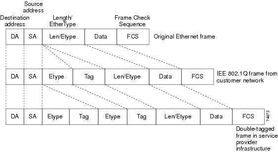
Figure 1 shows the tag structures of the double-tagged packets.
Figure 1 Original (Normal), 802.1Q, and Double-Tagged Ethernet Packet Formats
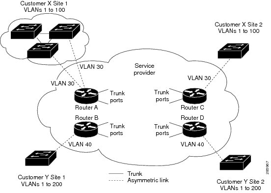
In Figure 2, Customer A was assigned VLAN 30, and Customer B was assigned VLAN 40. Packets entering the edge switches with 802.1Q tags are double-tagged when they enter the service-provider network, with the outer tag containing VLAN ID 30 or 40, appropriately, and the inner tag containing the original VLAN number, for example, VLAN 100. Even if both Customers A and B have VLAN 100 in their networks, the traffic remains segregated within the service-provider network because the outer tag is different. Each customer controls its own VLAN numbering space, which is independent of the VLAN numbering space used by other customers and the VLAN numbering space used by the service-provider network. At the outbound port, the original VLAN numbers on the customer's network are recovered.
Figure 2 802.1Q Tunnel Ports in a Service Provider Network
You can use EFPs to configure 802.1Q tunneling in two ways:
Method 1
In this example, for Customer A, interface Gigabit Ethernet 0/0/1 is the customer-facing port, and Gigabit Ethernet 0/0/2 is a trunk port facing the service provider network. For Customer B, Gigabit Ethernet 0/0/3 is the customer-facing port, and Gigabit Ethernet 0/0/4 is the trunk port facing the service provider network.
Customer A
Router (config)# interface gigabitethernet0/0/1Router (config-if)# service instance 1 EthernetRouter (config-if-srv)# encapsulation dot1q 1-100Router (config-if-srv)# bridge-domain 4000Router (config)# interface gigabitethernet0/0/2Router (config-if)# service instance 2 EthernetRouter (config-if-srv)# encapsulation dot1q 30Router (config-if-srv)# rewrite ingress pop 1 symmetricRouter (config-if-srv)# bridge-domain 4000For Customer A, service instance 1 on Gigabit Ethernet port 0/0/1 is configured with the VLAN encapsulations used by the customer: C-VLANs 1-100. These are forwarded on bridge-domain 4000. The service provider facing port is configured with a service instance on the same bridge-domain and with an encapsulation dot1q command matching the S-VLAN. The rewrite ingress pop 1 symmetric command also implies a push of the configured encapsulation on egress packets. Therefore, the original packets with VLAN tags between 1 and 100 are encapsulated with another S-VLAN (VLAN 30) tag when exiting Gigabit Ethernet port 0/0/2.
Similarly, for double- tagged (S-VLAN = 30, C-VLAN = 1-100) packets coming from the provider network, the rewrite ingress pop 1 symmetric command causes the outer S-VLAN tag to be popped and the original C-VLAN tagged frame to be forwarded over bridge-domain 4000 out to Gigabit Ethernet port 0/0/1.
The same scenario applies to Customer B.
Customer B
Router (config)# interface gigabitethernet0/0/3Router (config-if)# service instance 1 EthernetRouter (config-if-srv)# encapsulation dot1q 1-200Router (config-if-srv)# bridge-domain 4000Router (config)# interface gigabitethernet0/0/4Router (config-if)# service instance 2 EthernetRouter (config-if-srv)# encapsulation dot1q 40Router (config-if-srv)# rewrite ingress pop 1 symmetricRouter (config-if-srv)# bridge-domain 4000Method 2
QinQ is also supported when sending packets between an EFP and a trunk EFP, because the trunk is implicitly defined as rewrite ingress pop 1 symmetric. The same external behavior as Method 1 can be achieved with this configuration:
Customer A
Router (config)# interface gigabitethernet0/0/1Router (config-if)# service instance 1 EthernetRouter (config-if-srv)# encapsulation dot1q 1-100Router (config-if-srv)# bridge-domain 30Router (config)# interface gigabitethernet0/0/2Router (config-if)# service instance trunk 1 ethernetRouter (config-if-srv)# encapsulation dot1q 30Router (config-if-srv)# rewrite ingress pop 1 symmetricRouter (config-if-srv)# bridge-domain from-encapsulationAgain, service instance 1 on Gigabit Ethernet port 0/0/1 is configured with the VLAN encapsulations used by the customer. These are forwarded on bridge-domain 30. The service provider facing port is configured as a trunk port. The trunk port implicitly pushes a tag matching the bridge-domain that the packet is forwarded on (in this case S-VLAN 30).
For double tagged (S-VLAN = 30, C-VLAN = 1 to 100) packets coming in from the provider network, the trunk port implicitly pops the outer S-VLAN (30) and forwards the packet on that bridge-domain.
Customer B
Router (config)# interface gigabitethernet0/0/3Router (config-if)# service instance 1 EthernetRouter (config-if-srv)# encapsulation dot1q 1-200Router (config-if-srv)# bridge-domain 40Router (config)# interface gigabitethernet0/0/4Router (config-if)# service instance trunk 2 EthernetRouter (config-if-srv)# encapsulation dot1q 40Router (config-if-srv)# rewrite ingress pop 1 symmetricRouter (config-if-srv)# bridge-domain from-encapsulationYou can also combine the customer A and B configurations, as follows:
Customer A and B
Router (config)# interface gigabitethernet0/0/2Router (config-if)# service instance trunk 1 ethernetRouter (config-if-srv)# encapsulation dot1q 30,40Router (config-if-srv)# rewrite ingress pop 1 symmetricRouter (config-if-srv)# bridge-domain from-encapsulationFor information about the effect on cost of service (CoS) for different EFT tagging operations, see the Cisco ASR 903 Router Chassis Software Configuration Guide.
VLAN Translation Example Configurations
•
Router (config)# interface gigabitethernet0/0/1Router (config-if)# service instance 10 EthernetRouter (config-if-srv)# encapsulation dot1q 10Router (config-if-srv)# rewrite ingress tag pop 1 symmetricRouter (config-if-srv)# bridge-domain 10Egress port configuration:
Router (config)# interface gigabitethernet0/0/1Router (config-if)# service instance 10 EthernetRouter (config-if-srv)# encapsulation dot1q 20Router (config-if-srv)# rewrite ingress tag pop 1 symmetricRouter (config-if-srv)# bridge-domain 10•
Router (config)# interface gigabitethernet0/0/1Router (config-if)# service instance 10 EthernetRouter (config-if-srv)# encapsulation dot1q 10Router (config-if-srv)# rewrite ingress tag pop 1 symmetricRouter (config-if-srv)# bridge-domain 10Egress port configuration:
Router (config)# interface gigabitethernet0/0/2Router (config-if)# service instance 10 EthernetRouter (config-if-srv)# encapsulation dot1q 20 second dot1q 30Router (config-if-srv)# rewrite ingress tag pop 2 symmetricRouter (config-if-srv)# bridge-domain 10•
Router (config)# interface gigabitethernet0/0/1Router (config-if)# service instance 10 EthernetRouter (config-if-srv)# encapsulation dot1q 10 second-dot1q 20Router (config-if-srv)# rewrite ingress tag pop 2 symmetricRouter (config-if-srv)# bridge-domain 10Egress port configuration:
Router (config)# interface gigabitethernet0/0/2Router (config-if)# service instance 10 EthernetRouter (config-if-srv)# encapsulation dot1q 30Router (config-if-srv)# rewrite ingress tag pop 1 symmetricRouter (config-if-srv)# bridge-domain 10•
Router (config)# interface gigabitethernet0/0/1Router (config-if)# service instance 10 EthernetRouter (config-if-srv)# encapsulation dot1q 10 second-dot1q 20Router (config-if-srv)# rewrite ingress tag pop 2 symmetricRouter (config-if-srv)# bridge-domain 10Egress port configuration:
Router (config)# interface gigabitethernet0/0/2Router (config-if)# service instance 10 EthernetRouter (config-if-srv)# encapsulation dot1q 30 second-dot1q 40Router (config-if-srv)# rewrite ingress tag pop 2 symmetricRouter (config-if-srv)# bridge-domain 10Layer 2 Protocol Tunneling
Customers at different sites connected across a service-provider network need to use various Layer 2 protocols to scale their topologies to include all remote sites, as well as the local sites. STP must run properly, and every VLAN should build a proper spanning tree that includes the local site and all remote sites across the service-provider network. Cisco Discovery Protocol (CDP) must discover neighboring Cisco devices from local and remote sites.
VLAN Trunking Protocol (VTP) must provide consistent VLAN configuration throughout all sites in the customer network that are participating in VTP. Similarly, DTP, LACP, LLDP, PAgP, and UDLD can also run across the service-provider network.
When protocol tunneling is enabled, edge switches on the inbound side of the service-provider network encapsulate Layer 2 protocol packets with a special MAC address (0100.0CCD.CDD0) and send them across the service-provider network. Core switches in the network do not process these packets but forward them as normal (unknown multicast data) packets. Layer 2 protocol data units (PDUs) for the configured protocols cross the service-provider network and are delivered to customer switches on the outbound side of the service-provider network. Identical packets are received by all customer ports on the same VLANs with these results:
•
•
•
Customers use Layer 2 protocol tunneling to tunnel BPDUs through a service-provider network without interfering with internal provider network BPDUs.
Note
In Figure 3, Customer X has four switches in the same VLAN, which are connected through the service-provider network. If the network does not tunnel PDUs, switches on the far ends of the network cannot properly run STP, CDP, and other Layer 2 protocols. For example, STP for a VLAN on a switch in Customer X, Site 1, will build a spanning tree on the switches at that site without considering convergence parameters based on Customer X's switch in Site 2. This could result in the topology shown in Figure 4.
Figure 3 Layer 2 Protocol Tunneling
Figure 4 Layer 2 Network Topology without Proper Convergence
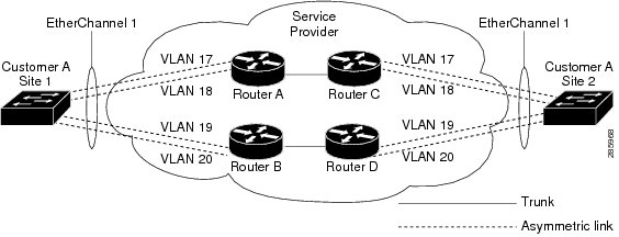
In a service-provider network, you can use Layer 2 protocol tunneling to enhance the creation of EtherChannels by emulating a point-to-point network topology. When you enable protocol tunneling (PAgP or LACP) on the service-provider switch, remote customer switches receive the PDUs and can negotiate the automatic creation of EtherChannels.
For example, in Figure 5, Customer A has two switches in the same VLAN that are connected through the SP network. When the network tunnels PDUs, switches on the far ends of the network can negotiate the automatic creation of EtherChannels without needing dedicated lines.
Figure 5 Layer 2 Protocol Tunneling for EtherChannels
Use the l2protocol tunnel protocol service-instance configuration command to enable Layer 2 protocol tunneling on a service instance:
Valid protocols include CDP, LACP, LLDP, PAgP, STP, UDLD, and VTP. If a protocol is not specified for a service instance, the protocol frame is dropped at the interface.
This is an example of Layer 2 protocol tunneling configuration:
Router (config)# interface gigabitethernet0/0/2Router (config-if)# service instance 10 EthernetRouter (config-if-srv)# encapsulation untagged, dot1q 200 second-dot1q 300Router (config-if-srv)# l2protocol tunnel cdp stp vtp dtp pagp lacpRouter (config-if-srv)# bridge-domain 10
Note
Note
EFPs and Ethernet over Multiprotocol Layer Switching (EoMPLS)
When you configure a pseudowire under a VLAN interface (for example, VLAN 33), the pseudowire becomes a virtual Layer 2 port in that VLAN (VLAN 33), or bridge domain. In this bridge domain, you can configure other types of Layer 2 ports, such as EFP portss. Switching functionalities, such as MAC address learning, flooding, and forwarding to learned MAC addresses, apply to all the Layer 2 ports, including the pseudowire.
Note
For more information about configuring pseudowire, see the Cisco ASR 903 Router Chassis Software Configuration Guide.
Bridge Domain Routing
The switch supports IP routing and multicast routing for bridge domains, including Layer 3 and Layer 2 VPNs, using the BDI model. There are the limitations:
•
•
•
This is an example of configuring bridge-domain routing with a single tag EFP:
Router (config)# interface gigabitethernet0/0/2Router (config-if)# service instance 1 EthernetRouter (config-if-srv)# encapsulation dot1q 10Router (config-if-srv)# rewrite ingress tag pop 1 symmetricRouter (config-if-srv)# bridge-domain 100Router (config)# interface bdi 100Router (config-if)# ip address 20.1.1.1 255.255.255.255This is an example of configuring bridge-domain routing with two tags:
Router (config)# interface gigabitethernet0/0/2Router (config-if)# service instance 1 EthernetRouter (config-if-srv)# encapsulation dot1q 10 second-dot1q 20Router (config-if-srv)# rewrite ingress tag pop 2 symmetricRouter (config-if-srv)# bridge-domain 100Router (config)# interface bdi 100Router (config-if)# ip address 20.1.1.1 255.255.255.255EFPs and Trunk Port MAC Addresses
Because forwarding can occur between EFPs and trunk ports, MAC address movement can occur on learned addresses. Addresses learned on EFPs will have the format of interface + EFP ID, for example gigabitethernet 0/0/1 + EFP 1. When an address moves between a non-secured EFP and a trunk port, the behavior is similar to that of moving between trunk ports.
To see MAC address information for bridge domains, use the show mac-address-table bdomain domain command.
When an EFP property changes (bridge domain, rewrite, encapsulation, split-horizon, secured or unsecured, or a state change), the old dynamic MAC addresses are flushed from their existing tables. This is to prevent old invalid entries from lingering.
EFPs and MSTP
EFP bridge domains are supported by the Multiple Spanning Tree Protocol (MSTP). These restrictions apply when running STP with bridge domains.
•
•
•
•
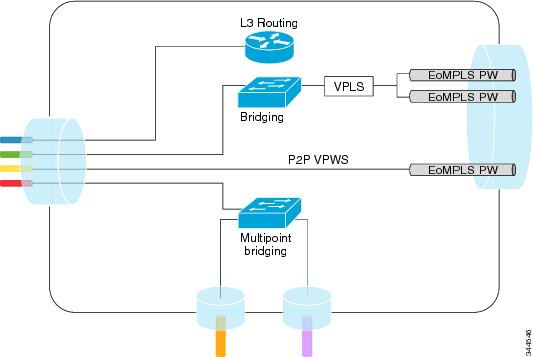
L3 Unicast and Multicast Routing on a Bridge Domain with Multiple EFPs
L3 unicast routing and L3 multicast routing are supported on bridge domains with multiple EFPs. This feature provides the following functionality:
•
•
•
Figure 6 shows an access-facing port with multiple EFPs configured to the route or bridge.
Figure 6
Multiple EFPs
Restrictions
IRB is required for L3 termination at the SVI with redundant L2 links.
For core-based deployments, MPLS is a preferred transport for any traffic type.
Configuring L3 Multicast Routing on a Bridge Domain
The following example shows how to configure L3 multicast routing on a bridge domain using existing IOS commands.
ip routingIp multicast-routing!!interface bdi 100ip address 1.1.1.1 255.255.255.0ip pim sparse-modeIgmp version v3!interface GigabitEthernet0/0/1service instance 1 ethernetencapsulation dot1q 33rewrite ingress tag pop 1 symmetricbridge-domain 100!service instance 2 ethernetencapsulation dot1q 55rewrite ingress tag pop 1 symmetricbridge-domain 100Cross-Connect on EFP Interfaces
Cross-connect provides the ability to match the encapsulation of received packets on the ingress side of an EFP interface and send them out with the same encapsulation through the egress side of the EFP interface. Cross-connect bridge-domain entries are provided, and encapsulation matching is achieved by matching bridge-domain entries for the EFPs on which cross-connect is configured.
The following types of encapsulation tags are supported:
•
•
Restrictions
•
•
•
Configuring Cross-Connect on an EFP Interface
Beginning in privileged EXEC mode, follow these steps to configure cross-Connect on an EFP Interface.
Summary Steps
1.
2.
3.
4.
5.
6.
Detailed Steps
This is an example configuration of cross-connect on an EFP interface:
interface gigabitethernet 0/0/3service instance 30 ethernetencap dot1q x second dot1q yxconnect <10.10.10.10> 123 encapsulation mplsConfiguring a Static MAC Address
This section describes how to configure a static MAC address on the Cisco ASR 903 Series Router. For an overview of static MAC addresses, see Static MAC Addresses.
Limitations
The following limitations apply when configuring static MAC addresses:
•
•
•
•
•
Configuring a Multicast Static MAC Address
Follow these steps to configure a multicast static MAC address.
Summary Steps
1.
2.
3.
4.
5.
6.
7.
Detailed Steps
Step 1
configure terminal
Enter global configuration mode.
Step 2
interface interface-id
Specify an interface to configure, and enter interface configuration mode.
Step 3
service instance number ethernet [name]
Configure an EFP (service instance) and enter service instance configuration) mode.
•
•
Step 4
encapsulation {default | dot1q | priority-tagged | untagged}
Configure encapsulation type for the service instance.
•
•
•
•
Step 5
bridge-domain bridge-id
Configure the bridge domain ID.
Step 6
mac static address address
Specifies the multicast MAC address.
Step 7
end
Return to privileged EXEC mode.
This is an example configuration of a static MAC address on an EFP interface:
interface gigabitEthernet 0/0/3service instance 10 ethernetencapsulation dot1q 10bridge-domain 100mac static address 1302.4302.23c3This configuration specifies that any layer 2 traffic sent to destination MAC address 1302.4302.23c3 is forwarded only to service instance 10 of bridge-domain interface gigabitEthernet 0/0/3.
To disable a static MAC configuration, apply the mac static address address command to the service instance:
Router (config)# interface gigabitethernet0/0/1Router (config-if)# service instance 1 EthernetRouter (config-if-srv)# mac static address 1302.4302.23c3Monitoring EVC
This is an example of output from the show ethernet service instance detail command:
Router# show ethernet service instance id 1 interface gigabitEthernet 0/0/1 detailService Instance ID: 1Associated Interface: GigabitEthernet0/0/13Associated EVC: EVC_P2P_10L2protocol dropCE-Vlans:Encapsulation: dot1q 10 vlan protocol type 0x8100Interface Dot1q Tunnel Ethertype: 0x8100State: UpEFP Statistics:Pkts In Bytes In Pkts Out Bytes Out214 15408 97150 6994800EFP Microblocks:****************Microblock type: Bridge-domainBridge-domain: 10This is an example of output from the show ethernet service instance statistics command:
Router# show ethernet service instance id 1 interface gigabitEthernet 0/0/13 statsService Instance 1, Interface GigabitEthernet0/0/13Pkts In Bytes In Pkts Out Bytes Out214 15408 97150 6994800This is an example of output from the show mac-address table count command:
Router# show mac address-table count bridge-domain 10Mac Entries for BD 10:---------------------------Dynamic Address Count : 20Static Address Count : 0Total Mac Addresses : 20