Table Of Contents
Configuring VPLS over MPLS-TP
Understanding VPLS over MPLS-TP
Multiprotocol Label Switching Overview
Virtual Private LAN Services Overview
VPLS over MPLS-TP Overview
References
Configuring VPLS over MPLS-TP
Configuration Guidelines
Configuring the MPLS Label Range
Configuring the Router ID and Global ID
Configuring the Pseudowire Class
Configuring a BFD Template
Configuring the MPLS-TP Tunnel
Configuring MPLS-TP Links and Physical Interfaces
Configuring an Output Interface
Configuring an Access Interface
Configuring the VFI in the PE
Configuring a Virtual Loopback Interface
Restrictions
Verifying the Configuration
Configuration Examples
Configuring VPLS over MPLS-TP
This chapter describes how to configure VPLS over MPLS-TP on the Cisco ASR 903 Series Router. This chapter includes the following section:
• Understanding VPLS over MPLS-TP
•Configuring VPLS over MPLS-TP
•Verifying the Configuration
•Configuration Examples
Understanding VPLS over MPLS-TP
The following sections provide an overview of VPLS over MPLS-TP:
•Multiprotocol Label Switching Overview
•Virtual Private LAN Services Overview
•VPLS over MPLS-TP Overview
•References
Multiprotocol Label Switching Overview
The Multiprotocol Label Switching (MPLS) Transport Profile (TP) enables you to create tunnels that provide the transport network service layer over which IP and MPLS traffic traverse. MPLS-TP tunnels enable a transition from Synchronous Optical Networking (SONET) and Synchronous Digital Hierarchy (SDH) time-division multiplexing (TDM) technologies to packet switching to support services with high bandwidth requirements, such as video.
Virtual Private LAN Services Overview
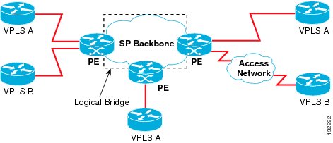
Virtual Private LAN Services (VPLS) uses the provider core to join multiple attachment circuits together to simulate a virtual bridge that connects the multiple attachment circuits together. From a customer point of view, there is no topology for VPLS. All of the CE devices appear to connect to a logical bridge emulated by the provider core. See Figure 13-1.
Figure 13-1 VPLS
Full-mesh, hub and spoke, and Hierarchical VPLS (H-VPLS) with MPLS edge configurations are available.
VPLS over MPLS-TP Overview
VPLS over MPLS-TP allows you to deploy a multipoint-to-multipoint layer 2 operating environment over an MPLS-TP network for services such as Ethernet connectivity and multicast video.
References
For detailed information about the commands, see:
•Cisco IOS XE 3.5 MPLS Command Reference: http://www.cisco.com/en/US/docs/ios/cether/command/reference/ce_book.html
•Master Command Index for Cisco IOS XE Release 3.5: http://www.cisco.com/en/US/docs/ios/mcl/allreleasemcl/all_book.html
Configuring VPLS over MPLS-TP
The following sections describe how to configure VPLS over MPLS-TP:
•Configuration Guidelines
•Configuring the MPLS Label Range
•Configuring the Router ID and Global ID
•Configuring the Pseudowire Class
•Configuring the MPLS-TP Tunnel
•Configuring MPLS-TP Links and Physical Interfaces
•Configuring the VFI in the PE
•Configuring a Virtual Loopback Interface
Configuration Guidelines
VPLS over MPLS-TP is only supported on Gigabit Ethernet and Ten Gigabit Ethernet interfaces.
Configuring the MPLS Label Range
You must specify a static range of MPLS labels using the mpls label range command with the static keyword.
SUMMARY STEPS
1. enable
2. configure terminal
3. mpls label range minimum-value maximum-value {static minimum-static-value maximum-static-value}
DETAILED STEPS
| |
Command or Action
|
Purpose
|
Step 1
|
enable
Example:
Router> enable
|
Enables privileged EXEC mode.
•Enter your password if prompted.
|
Step 2
|
configure terminal
Example:
Router# configure terminal
|
Enters global configuration mode.
|
Step 3
|
mpls label range minimum-value maximum-value
{static minimum-static-value
maximum-static-value}
Example:
Router(config)# mpls label range 1001 1003
static 10000 25000
|
Specifies a static range of MPLS labels
|
Configuring the Router ID and Global ID
SUMMARY STEPS
1. enable
2. configure terminal
3. mpls tp
4. router-id node-id
5. global-id num
DETAILED STEPS
| |
Command or Action
|
Purpose
|
Step 1
|
enable
Example:
Router> enable
|
Enables privileged EXEC mode.
•Enter your password if prompted.
|
Step 2
|
configure terminal
Example:
Router# configure terminal
|
Enters global configuration mode.
|
Step 3
|
mpls tp
Example:
Router(config)# mpls tp
|
Enters MPLS-TP configuration mode, from which you can configure MPLS-TP parameters for the router.
|
Step 4
|
router-id node-id
Example:
Router(config-mpls-tp)# router-id 10.10.10.10
|
Specifies the default MPLS-TP router ID, which is used as the default source node ID for all MPLS-TP tunnels configured on the router.
|
Step 5
|
global-id num
Example:
Router(config-mpls-tp)# global-id 1
|
(Optional) Specifies the default global ID used for all endpoints and midpoints. This command makes the router ID globally unique in a multiprovider tunnel. Otherwise, the router ID is only locally meaningful. The global ID is an autonomous system number, which is a controlled number space by which providers can identify each other.
The router ID and global ID are also included in fault messages by routers at tunnel midpoints to help isolate the location of faults.
|
Configuring the Pseudowire Class
When you create the pseudowire class, you specify the parameters of the pseudowire, such as the use of the control word, and preferred path.
SUMMARY STEPS
1. enable
2. configure terminal
3. pseudowire-class class-name
4. encapsulation mpls
5. control-word
6. protocol {l2tpv2 | l2tpv3 | none} [l2tp-class-name]
7. preferred-path {interface tunnel tunnel-number | peer {ip-address | host-name}} [disable-fallback]
DETAILED STEPS
| |
Command or Action
|
Purpose
|
Step 1
|
enable
Example:
Router> enable
|
Enables privileged EXEC mode.
•Enter your password if prompted.
|
Step 2
|
configure terminal
Example:
Router# configure terminal
|
Enters global configuration mode.
|
Step 3
|
pseudowire-class class-name
Example:
Router(config)# pseudowire-class mpls-tp-class1
|
Creates a pseudowire class and enters pseudowire class configuration mode.
|
Step 4
|
encapsulation mpls
Example:
Router(config-pw-class)# encapsulation mpls
|
Specifies the encapsulation type.
|
Step 5
|
control-word
Example:
Router(config-pw-class)# control-word
|
Enables the use of the control word.
|
Step 6
|
protocol {l2tpv2 | l2tpv3 | none}
[l2tp-class-name]
Example:
Router(config-pw-class)# protocol none
|
Specifies the type of protocol.
|
Step 7
|
preferred-path {interface tunnel tunnel-number
| peer {ip-address | host-name}}
[disable-fallback]
Example:
Router(config-pw-class)# preferred-path
interface tunnel-tp2
|
Specifies the tunnel to use as the preferred path.
|
Step 8
|
end
Example:
Router(config-pw-class)# end
Router#
|
Exits configuration mode.
|
Configuring a BFD Template
1. enable
2. configure terminal
3. bfd-template single-hop template-name
4. interval microseconds {both microseconds | min-tx microseconds min-rx microseconds} [multiplier multiplier-value]
5. interval {both milliseconds | min-tx milliseconds min-rx milliseconds} [multiplier multiplier-value]
6. end
DETAILED STEPS
| |
Command or Action
|
Purpose
|
Step 1
|
enable
Example:
Router> enable
|
Enables privileged EXEC mode.
•Enter your password if prompted.
|
Step 2
|
configure terminal
Example:
Router# configure terminal
|
Enters global configuration mode.
|
Step 3
|
bfd-template single-hop template-name
Example:
Router(config)# bfd-template single-hop
bfdtemplate1
|
Creates a BFD template and enters BFD configuration mode.
The bfd-template command allows you to create a BFD template and enters BFD configuration mode. The template can be used to specify a set of BFD interval values. You can then invoke the BFD template when you set up the MPLS-TP tunnel.
|
Step 4
|
interval microseconds {both microseconds | min-tx microseconds min-rx microseconds} [multiplier multiplier-value]
Example:
Router(config-bfd)# interval microseconds both
3300 multiplier 3
|
Configures the transmit and receive intervals in microseconds between BFD packets, and specifies the number of consecutive BFD control packets that must be missed from a BFD peer before BFD declares that a peer is unavailable.
|
Step 5
|
interval {both milliseconds | min-tx milliseconds min-rx milliseconds} [multiplier multiplier-value]
Example:
Router(config-bfd)# interval both 120
multiplier 3
|
Configures the transmit and receive intervals in milliseconds between BFD packets, and specifies the number of consecutive BFD control packets that must be missed from a BFD peer before BFD declares that a peer is unavailable.
|
Step 6
|
end
Example:
Router(config-bfd)# end
Router#
|
Exits configuration mode.
|
Configuring the MPLS-TP Tunnel
On the endpoint routers, create an MPLS TP tunnel and configure its parameters. See the interface tunnel-tp command for information on the parameters.
SUMMARY STEPS
1. enable
2. configure terminal
3. interface tunnel-tp number
4. description tunnel-description
5. tp tunnel-name name
6. tp source mode-id [global-id num]
7. tp destination node-id [[tunnel-tp num] global-id num]
8. bfd bfd-template
9. working-lsp
10. in-label num
11. out-label num out-link num
12. exit
13. protect-lsp
14. in-label num
15. out-label num out-link num
16. exit
DETAILED STEPS
| |
Command or Action
|
Purpose
|
Step 1
|
enable
Example:
Router> enable
|
Enables privileged EXEC mode.
•Enter your password if prompted.
|
Step 2
|
configure terminal
Example:
Router# configure terminal
|
Enters global configuration mode.
|
Step 3
|
interface tunnel-tp number
Example:
Router(config)# interface tunnel-tp 2
|
Enters tunnel interface configuration mode. Tunnel numbers from 0 to 999 are supported.
|
Step 4
|
description tunnel-description
Example:
Router(config-if)# description headend tunnel
|
(Optional) Specifies a tunnel description.
|
Step 5
|
tp tunnel-name name
Example:
Router(config-if)# tp tunnel-name tunnel22
|
Specifies the name of the MPLS-TP tunnel. The TP tunnel name is displayed in the show mpls tp tunnel command output. This command is useful for consistently identifying the tunnel at all endpoints and midpoints.
|
Step 6
|
tp source node-id [global-id num]
Example:
Router(config-if)# tp source 10.10.11.11
global-id 10
|
(Optional) Specifies the tunnel source and endpoint. This command is and not typically used, because the global router ID and global ID can be used to identify the tunnel source at the endpoint. All tunnels on the router generally use the same (globally specified) source information.
|
Step 7
|
tp destination node-id [[tunnel-tp num]
global-id num]
Example:
Router(config-if)# tp destination 10.10.10.10
|
Specifies the destination node of the tunnel.
|
Step 8
|
bfd bfd-template
Example:
Router(config-if)# bfd mpls-tp-bfd-2
|
Specifies the BFD template.
|
Step 9
|
working-lsp
Example:
Router(config-if)# working-lsp
|
Specifies a working LSP, also known as the primary LSP. This LSP is used to route traffic. This command enters working LSP interface configuration mode (config-if-working).
|
Step 10
|
in-label num
Example:
Router(config-if-working)# in-label 111
|
Specifies the in label.
|
Step 11
|
out-label num out-link num
Example:
Router(config-if-working)# out-label 112
out-link 1
|
Specifies the out label and out link.
|
Step 12
|
exit
Example:
Router(config-if-working)# exit
|
Exits from working LSP interface configuration mode.
|
Step 13
|
protect-lsp
Example:
Router(config-if)# protect-lsp
|
Specifies a backup for a working LSP. If the working LSP fails, traffic is switched to the protect LSP until the working LSP is restored, at which time forwarding reverts back to the working LSP. This command enters protect LSP interface configuration mode (config-if-protect).
|
Step 14
|
in-label num
Example:
Router(config-if-protect)# in-label 100
|
Specifies the in label.
|
Step 15
|
out-label num out-link num
Example:
Router(config-if-protect)# out-label 113
out-link 2
|
Specifies the out label and out link.
|
Step 16
|
exit
Example:
Router(config-if-protect)# exit
|
Exits from protect LSP interface configuration mode.
|
Configuring MPLS-TP Links and Physical Interfaces
MPLS-TP link numbers may be assigned to physical interfaces only. Bundled interfaces and virtual interfaces are not supported for MPLS-TP link numbers.
The following sections describe how to configure physical interfaces for a VPLS over MPLS-TP link.
•Configuring an Output Interface
•Configuring an Access Interface
Configuring an Output Interface
Follow these steps to configure an output interfaces.
SUMMARY STEPS
1. enable
2. configure terminal
3. interface type/num
4. no ip address
5. mpls tp link link-num {ipv4 ip-address | tx-mac mac-address}
6. ip rsvp bandwidth [rdm [bc0 interface-bandwidth] [[single-flow-bandwidth [bc1 bandwidth | sub-pool bandwidth]]] [interface-bandwidth [single-flow-bandwidth [bc1 bandwidth | sub-pool bandwidth]] | mam max-reservable-bw [interface-bandwidth [single-flow-bandwidth] [bc0 interface-bandwidth [bc1 bandwidth]]] | percent percent-bandwidth [single-flow-bandwidth]]
7. exit
8. exit
9. show mpls tp link-numbers
DETAILED STEPS
| |
Command or Action
|
Purpose
|
Step 1
|
enable
Example:
Router> enable
|
Enables privileged EXEC mode.
•Enter your password if prompted.
|
Step 2
|
configure terminal
Example:
Router# configure terminal
|
Enters global configuration mode.
|
Step 3
|
interface type/num
Example:
Router(config)# interface ethernet 1/0
|
Specifies the interface and enters interface configuration mode.
|
Step 4
|
no ip address
Example:
Router(config-if)# no ip address
|
Specifies that there is no IP address assigned to the interface.
|
Step 5
|
negotiation auto
Example:
Router(config-if)# negotiation auto
|
Enables the autonegotiation protocol to configure the speed, duplex, and automatic flow control of the Gigabit Ethernet interface.
|
Step 6
|
mpls tp link link-num {ipv4 ip-address | tx-mac
mac-address}
Example:
Router(config-if)# mpls tp link 1 ipv4 10.0.0.2
|
Associates an MPLS-TP link number with a physical interface and next-hop node. On point-to-point interfaces or Ethernet interfaces designated as point-to-point using the medium p2p command, the next-hop can be implicit, so the mpls tp link command just associates a link number to the interface.
Multiple tunnels and LSPs can refer to the MPLS-TP link to indicate they are traversing that interface. You can move the MPLS-TP link from one interface to another without reconfiguring all the MPLS-TP tunnels and LSPs that refer to the link.
Link numbers a must be unique on the router or node.
|
Step 7
|
ip rsvp bandwidth [rdm [bc0
interface-bandwidth] [[single-flow-bandwidth
[bc1 bandwidth | sub-pool bandwidth]]]
[interface-bandwidth [single-flow-bandwidth
[bc1 bandwidth | sub-pool bandwidth]] | mam
max-reservable-bw [interface-bandwidth
[single-flow-bandwidth] [bc0
interface-bandwidth [bc1 bandwidth]]] | percent
percent-bandwidth [single-flow-bandwidth]]
Example:
Router(config-if)# ip rsvp bandwidth 1158 100
|
Enables Resource Reservation Protocol (RSVP) bandwidth for IP on an interface.
For the Cisco 7600 platform, if you configure non-zero bandwidth for the TP tunnel or at a midpoint LSP, make sure that the interface to which the output link is attached has enough bandwidth available. For example, if three tunnel LSPs run over link 1 and each LSP was assigned 1000 with the tp bandwidth command, the interface associated with link 1 needs bandwidth of 3000 with the ip rsvp bandwidth command.
|
Step 8
|
exit
Example:
Router(config-if)# exit
|
Exits interface configuration mode.
|
Step 9
|
exit
Example:
Router(config)# exit
|
Exits global configuration mode.
|
Step 10
|
show mpls tp link-numbers
Example:
Router# show mpls tp link-numbers
|
Displays the configured links.
|
Configuring an Access Interface
Follow these steps to configure an access interface.
SUMMARY STEPS
1. enable
2. configure terminal
3. interface type/num
4. no ip address
5. negotiation auto
6. service instance id service-type
7. encapsulation dot1q vlan-id second-dot1q {any | vlan-id | vlan-id-vlan-id[,vlan-id-vlan-id]}
8. bridge-domain vlan-id [access | dot1q [tag] | dot1q-tunnel] [broadcast] [ignore-bpdu-pid] [pvst-tlv CE-vlan] [increment] [lan-fcs] [split-horizon]
9. exit
DETAILED STEPS
| |
Command or Action
|
Purpose
|
Step 1
|
enable
Example:
Router> enable
|
Enables privileged EXEC mode.
•Enter your password if prompted.
|
Step 2
|
configure terminal
Example:
Router# configure terminal
|
Enters global configuration mode.
|
Step 3
|
interface type/num
Example:
Router(config)# interface gigabitethernet 1/0
|
Specifies the interface and enters interface configuration mode.
|
Step 4
|
no ip address
Example:
Router(config-if)# no ip address
|
Specifies that there is no IP address assigned to the interface.
|
Step 5
|
negotiation auto
Example:
Router(config-if)# negotiation auto
|
Enables the autonegotiation protocol to configure the speed, duplex, and automatic flow control of the Gigabit Ethernet interface.
|
Step 6
|
service instance id service-type
Router(config)# service instance 1 ethernet
|
Configures an Ethernet service instance.
|
Step 7
|
encapsulation dot1q vlan-id second-dot1q {any |
vlan-id | vlan-id-vlan-id[,vlan-id-vlan-id]}
Router(config-if)# encapsulation dot1q 2
|
Enables IEEE 802.1Q encapsulation of traffic on a specified subinterface in a VLAN.
|
Step 8
|
bridge-domain vlan-id [access | dot1q [tag] |
dot1q-tunnel] [broadcast] [ignore-bpdu-pid]
[pvst-tlv CE-vlan] [increment] [lan-fcs]
[split-horizon]
Example:
Router(config-if)# bridge-domain 1000
|
Places the interface in the same bridge domain as the VFI interface.
|
Step 9
|
exit
Example:
Router(config-if)# exit
|
Exits interface configuration mode.
|
Configuring the VFI in the PE
The virtual switch instance (VFI) specifies the VPN ID of a VPLS domain, the addresses of other PE routers in this domain, and the type of tunnel signaling and encapsulation mechanism for each peer. (This is where you create the VSI and associated VCs.) Configure a VFI as follows:
Note Only MPLS encapsulation is supported.
SUMMARY STEPS
1. l2 vfi name manual
2. vpn id vpn-id
3. bridge-domain vlan-id [access | dot1q [tag] | dot1q-tunnel] [broadcast] [ignore-bpdu-pid] [pvst-tlv CE-vlan] [increment] [lan-fcs] [split-horizon]
4. neighbor remote router id [vc-id-value] {encapsulation mpls} [no-split-horizon]
5. shutdown
DETAILED STEPS
| |
Command or Action
|
Purpose
|
Step 1
|
Example:
Router(config)# l2 vfi vfi17 manual
|
Enables the Layer 2 VFI manual configuration mode.
|
Step 2
|
Example:
Router(config-vfi)# vpn id 17
|
Configures a VPN ID for a VPLS domain. The emulated VCs bound to this Layer 2 VRF use this VPN ID for signaling.
|
Step 3
|
bridge-domain vlan-id [access | dot1q [tag] |
dot1q-tunnel] [broadcast] [ignore-bpdu-pid]
[pvst-tlv CE-vlan] [increment] [lan-fcs]
[split-horizon]
Example:
Router(config-vfi)# bridge-domain 191
|
Places the VFI in the same bridge domain as the access interface.
|
Step 4
|
neighbor remote router id
[vc-id-value]{encapsulation mpls}
[no-split-horizon]
Example:
Router(config-vfi)# neighbor 1.5.1.1 101
encapsulation mpls
|
Specifies the remote peering router ID and the tunnel encapsulation type or the pseudo wire property to be used to set up the emulated VC.
Note Split horizon is the default configuration to avoid broadcast packet looping and to isolate Layer 2 traffic. Use the no-split-horizon keyword to disable split horizon and to configure multiple VCs per spoke into the same VFI.
Note The optional VC ID value identifies the emulated VC between a pair of peering PE routers.
|
Step 5
|
Example:
Router(config-vfi)# shutdown
|
Disconnects all emulated VCs previously established under the Layer 2 VFI and prevents the establishment of new attachment circuits.
Note It does not prevent the establishment of new attachment circuits configured with the Layer 2 VFI using CLI.
|
Configuring a Virtual Loopback Interface
This task explains how to configure a basic loopback interface.
Restrictions
The IP address of a loopback interface must be unique across all routers on the network. It must not be used by another interface on the router, and it must not be used by an interface on any other router on the network.
SUMMARY STEPS
1. configure
2. interface loopback interface-path-id
3. ipv4 address ip-address
4. end
5. show interfaces type interface-path-id
DETAILED STEPS
| |
Command or Action
|
Purpose
|
Step 1
|
configure
Example:
Router# configure terminal
|
Enters global configuration mode.
|
Step 2
|
interface loopback interface-path-id
Example:
Router#(config)# interface Loopback 3
|
Enters interface configuration mode and names the new loopback interface.
|
Step 3
|
ipv4 address ip-address
Example:
Router(config-if)# ipv4 address 172.18.189.38
|
Assigns an IP address and subnet mask to the virtual loopback interface using the ipv4 address configuration command.
|
Step 4
|
end
Example:
Router(config-if)# end
|
Saves configuration changes.
•When you issue the end command, the system prompts you to commit changes:
Uncommitted changes found, commit them before
exiting(yes/no/cancel)?
–Entering yes saves configuration changes to the running configuration file, exits the configuration session, and returns the router to EXEC mode.
–Entering no exits the configuration session and returns the router to EXEC mode without committing the configuration changes.
–Entering cancel leaves the router in the current configuration session without exiting or committing the configuration changes.
•Use the commit command to save the configuration changes to the running configuration file and remain within the configuration session.
|
Step 5
|
show interfaces type interface-path-id
Example:
RP/0/0/CPU0:router# show interfaces Loopback 3
|
(Optional) Displays the configuration of the loopback interface.
|
Verifying the Configuration
You can use the following commands to verify your configuration:
•show mpls l2transport vc—Displays information about Any Transport over MPLS (AToM) virtual circuits (VCs) and static pseudowires that have been enabled to route Layer 2 packets on the router.
•show mpls tp—Displays information about Multiprotocol Label Switching (MPLS) transport profile (TP) tunnels.
•show bfd summary—Displays summary information for Bidirectional Forwarding Protocol (BFD).
•show xconnect—Displays information about xconnect attachment circuits and pseudowires.
You can use the following commands to debug your configuration:
•debug mpls tp all—Debug for all MPLS-TP information.
•debug mpls tp cli—Debug for MPLS-TP CLI
•debug mpls tp error—Debug for MPLS-TP errors
•debug mpls tp event—Debug for MPLS events
•debug mpls tp fault-oam—Debug for Fault-OAM
•debug mpls tp ha—Debug for High availability
•debug mpls tp init—Debug for MPLS-TP initialization
•debug mpls tp link-management—Debug for link management
•debug mpls tp link-num—Debug for link number database
•debug mpls tp lsp-db—Debug for LSP database
•debug mpls tp lsp-ep—Debug for endpoint LSP configuration and operation
•debug mpls tp lsp-mp—Debug for midpoint LSP configuration and operation
•debug mpls tp mem—Debug for memory allocation and usage
•debug mpls tp tun-db—Debug for the tunnel database
•debug mpls tp tunnel—Debug for tunnel configuration and operation
Configuration Examples
PE Configuration
mpls label range 1001 4000 static 16 1000
bfd-template single-hop testbfd
interval microseconds min-tx 50000 min-rx 50000 multiplier 3
interface GigabitEthernet0/0/0
mpls tp link 2 tx-mac 88f0.7768.2300
interface GigabitEthernet0/2/0
mpls tp link 1 tx-mac 88f0.7768.2310
tp source 10.10.10.10 global-id 0
tp destination 192.168.1.1 global-id 0
preferred-path interface Tunnel-tp1
neighbor 192.168.1.1 pw-class myclass
ip address 10.10.10.10 255.255.255.255
interface GigabitEthernet0/1/0
service instance 1 ethernet
P Configuration (Midpoint)
ip address 9.9.9.9 255.255.255.255
mpls label range 1001 4000 static 16 1000
mpls tp lsp source 10.10.10.10 tunnel-tp 1 lsp working destination 192.168.1.1 tunnel-tp 1
in-label 100 out-label 300 out-link 1
in-label 400 out-label 200 out-link 2
out-link 1 connected to 192.168.1.1
out-link 2 connected to 10.10.10.10
 Feedback