Feedback Feedback
|
Table Of Contents
Configuring Microwave 1+1 Hot Standby Protocol on the Cisco ASR 903 Series Router
Understanding Microwave 1+1 Hot Standby Protocol
Suspending Continuity Check Messages
Configuring Microwave 1+1 Hot Standby Protocol
Configuring Microwave 1+1 Hot Standby Protocol on the Cisco ASR 903 Series Router
The following sections describe the Microwave 1+1 Hot Standby (HSBY) Protocol:
•
Understanding Microwave 1+1 Hot Standby Protocol
•
Understanding Microwave 1+1 Hot Standby Protocol
•
Overview
Microwave 1+1 Hot Standby Protocol (HSBY) is a link protection protocol developed by Nokia Siemens Networks. HSBY extends the functionality of CFM Continuity Check messages to enable detection and handling of hardware failures in microwave devices in order to provide redundancy. HSBY provides link protection support for indoor units (IDUs) and outdoor units (ODUs).
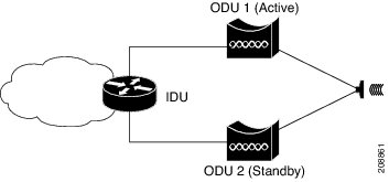
Figure 1 shows a sample physical topology for HSBY using two ODUs (active and standby) and one IDU.
Figure 1 HSBY Link Protection Physical Topology
In this topology, the IDU is connected to an active and a standby ODU. While only the active ODU handles data traffic, both ODUs process CFM and management traffic at all times. The HSBY implementation of CFM detects connectivity failures between the IDU and each ODU and indicates which ODU is active and handling traffic. In the event of a failure, the standby ODU assumes the role of the active ODU.
Suspending Continuity Check Messages
Under some circumstances such as a software upgrade or a device reload, it is necessary to temporarily suspend continuity check messages between the ODU and IDU in order to prevent unnecessary link protection action such as a failover. In this case, the ODU sets a suspend flag within the continuity check messages sent to the IDU indicating the amount of time until continuity check messages resume. The IDU resumes exchanging continuity check messages with the ODU after the suspend interval has passed or after the ODU recovers sends a continuity check message.
Note
HSBY Maintenance Associations
HSBY protocol uses two types of CFM continuity check messages:
•
•
Note
Thus, the HSBY configuration shown in Figure 1 consists of five separate traffic flows:
•
•
•
•
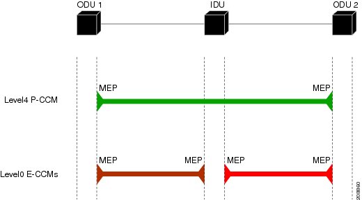
Figure 2 provides a logical view of the maintenance associations used in this HSBY topology.
Figure 2 HSBY Protocol CFM Maintenance Associations
Note
Configuring Microwave 1+1 Hot Standby Protocol
The following sections describe how to configure Microwave 1+1 Hot Standby Protocol (HSBY) on the Cisco ASR 903 Series Router.
ODU Configuration Values
HSBY protocol specifies that some values on the ODU are configurable while others utilize fixed values. Table 1 summarizes the permitted values for an ODU using HSBY protocol.
Table 1 HSBY ODU Configuration Parameters Summary
Short MA Name
Learned
0-65535
MPID
2
Fixed
MA VLAN-ID (P-CCM)
None
16-50
IDU Configuration Values
HSBY protocol specifies that some values on the IDU are configurable while others utilize fixed values. Table 2 summarizes the permitted values for an IDU using HSBY protocol.
Configuring HSBY
Follow these steps to configure HSBY protocol on the Cisco ASR 903 Series Router.
Summary Steps
1.
2.
3.
4.
5.
6.
7.
8.
9.
10.
11.
12.
13.
14.
15.
16.
17.
18.
19.
20.
21.
22.
23.
24.
25.
26.
27.
28.
29.
30.
31.
32.
33.
34.
35.
36.
37.
38.
39.
40.
Configuration Examples
This section contains configuration examples for HSBY protocol.
HSBY Sample Configuration
The following configuration example shows how to configure HSBY. This example uses EVC interfaces, which are the only supported interfaces for HSBY on the Cisco ASR 903 Series Router.
!link-protection enablelink-protection suspend-interval 320link-protection group 1link-protection management-vlan 500!ethernet cfm ieeeethernet cfm global!ethernet cfm domain ECCM1 level 0id nullservice number 1 evc EVCODU1 vlan 10 direction downcontinuity-checkcontinuity-check interval 10ms!ethernet cfm domain ECCM2 level 0id nullservice number 1 evc EVCODU2 vlan 11 direction downcontinuity-checkcontinuity-check interval 10ms!!interface GigabitEthernet0/0/1spanning-tree portfast trunkservice instance 1 ethernet EVCODU1description ODU1-ECCM-EVCencapsulation dot1q 10bridge-domain 10ethernet cfm mep domain ECCM1 mpid 100 vlan 10link-protection group 1!service instance 2 ethernetdescription ODU1-Management-Vlanencapsulation dot1q 500bridge-domain 500!service instance trunk 3 ethernetdescription ODU1-Data-Vlanencapsulation dot1q 100-200bridge-domain from-encapsulation!!interface GigabitEthernet0/0/2spanning-tree portfast trunkservice instance 2 ethernet EVCODU2description ODU2-ECCM-EVCencapsulation dot1q 10bridge-domain 10ethernet cfm mep domain ECCM2 mpid 100 vlan 11link-protection group 1!service instance 2 ethernetdescription ODU1-Management-Vlanencapsulation dot1q 500bridge-domain 500!service instance trunk 3 ethernetdescription ODU1-Data-Vlanencapsulation dot1q 100-200rewrite ingress tag pop 1 symmetricbridge-domain from-encapsulation