Feedback Feedback
|
Table Of Contents
Release Notes for Cisco Aironet Access Points and Bridges for Cisco IOS Release 12.4(21a)JY
Finding the Cisco IOS Software Release
Upgrading to a New Software Release
Installation in Environmental Air Space
Default SSID and Distance Settings Change When You Change Role in Radio Network
Default Encryption Key 2 Is Set by Bridge
Limitation to PAgP Redundancy on Switches Connected by Bridge Links
CLI Command power client n Is Not Supported
ARP Table Is Corrupted When Multiple BVIs Are Configured
Bridge Cannot Detect Simultaneous Image Downloads
Bridge Cannot Detect Invalid Software When Using copy Command
Telnet Session Sometimes Hangs or Will Not Start During Heavy Traffic
Synchronize IOS Supplicant Clocks and Save Time Setting to NVRAM
Access Point Creates File When Radar is Detected on a DFS Channel
Access Points Send Multicast and Management Frames at Highest Basic Rate
LWAPP to Autonomous Conversion Requires Two Reboots
Interpreting the Show Controller Dot11Radio Active Power Level Output
Enabling a Crash File for 1250 Series Access Points
Low Throughput Seen on 1140 and 1250 Series Access Points with 16 BSSIDs Configured
802.11n HT Rates Apply Only to No Encryption or WPA2/AES Encryption
Layer 3 Not Supported with NAC for MBSSID
Change to Default IP Address Behavior
Changes to the Default Configuration—Radios Disabled and No Default SSID
Clients Using WPA/WPA2 and Power Save May Fail to Authenticate
Default Username and Password Are Cisco
Some Client Devices Cannot Associate When QoS Is Configured
Some Devices Disassociate When Multiple BSSIDs Are Added or Deleted
Enabling MBSSIDs Without VLANs Disables Radio Interface
Cannot Set Channel on DFS-Enabled Radios in Some Regulatory Domains
Cisco 7920 Phones Require Firmware Version 1.09 or Later When Multiple BSSIDs Are Enabled
GRE Tunnelling Through WLSM Sometimes Requires MTU Setting Adjustments
TACACS+ and DHCP IP Address Sometimes Locks Out Administrators
Access Points Do Not Support Loopback Interface
Non-Cisco Aironet 802.11g Clients Might Require Firmware Upgrade
Throughput Option for 802.11g Radio Blocks Association by 802.11b Clients
Use Auto for Ethernet Duplex and Speed Settings
Use force-reload Option with archive download-sw Command
Radio MAC Address Appears in ACU
Radio MAC Address Appears in Access Point Event Log
Mask Field on IP Filters Page Behaves the Same As in CLI
Repeater Access Points Cannot Be Configured as WDS Access Points
Corrupt EAP Packet Sometimes Causes Error Message
When Cipher Is TKIP Only, Key Management Must Be Enabled
Cisco CKM Supports Spectralink Phones
Non-Cisco Aironet Clients Sometimes Fail 802.1x Authentication
Pings and Link Tests Sometimes Fail to Clients with Both Wired and Wireless Network Connections
Layer 3 Mobility Not Supported on Repeaters and Workgroup Bridges
WLSM Required for Layer 3 Mobility
Obtaining Documentation, Obtaining Support, and Security Guidelines
Release Notes for Cisco Aironet Access Points and Bridges for Cisco IOS Release 12.4(21a)JY
April 2010
These release notes describe caveats and features for Cisco IOS Release 12.4(21a)JY. This maintenance release supports 32+Mb Cisco autonomous access points, including Cisco Aironet 1130, 1140, 1240, and 1250 series access points, and 1300 and 1400 series access points/bridges.
Cisco Aironet 1100, 1200, and 1230 series 16-Mb autonomous access points require the companion maintenance release, Cisco IOS Release 12.3(8)JED1.
Note
A device that runs Cisco IOS software whose supplicant is configured to perform certificate-based authentication of its network connection may be unable to connect to the network unless it is configured to acquire the time from an NTP server. Follow the steps in the X section to make sure all the wireless devices on your network can perform certificate-based authentication.
Contents
These release notes contain the following sections:
•
Introduction
The Cisco Aironet Access Point is a wireless LAN transceiver that acts as the connection point between wireless and wired networks or as the center point of a standalone wireless network. In large installations, the roaming functionality provided by multiple access points enables wireless users to move freely throughout the facility while maintaining uninterrupted access to the network.
You can configure and monitor 1130, 1140, 1240, 1250 series access points, and 1300 and 1400 series access points/bridges by using the command-line interface (CLI), the web-browser interface, or Simple Network Management Protocol (SNMP).
System Requirements
You can install Cisco IOS Release 12.4(21a)JY on all 1130, 1140, 1240, 1250 series access points, 1300 series outdoor access point/bridges, and 1400 series bridges.
Finding the Cisco IOS Software Release
To find the version of Cisco IOS software running on your access point, use a Telnet session to log into the access point, and enter the show version EXEC command. This example shows command output from an access point running Cisco IOS Release 12.4(21a)JY :
ap1240AG> show versionCisco Internetwork Operating System SoftwareIOS (tm) C1240 Software (C1240-K9W7-M), Version 12.4(21a)JYCopyright (c) 1986-2009 by Cisco Systems, Inc.On access points running Cisco IOS software, you can also find the software release on the System Software Version page in the access point's web-browser interface. If your access point does not run Cisco IOS software, the software release appears at the top left of most pages in the web-browser interface.
Upgrading to a New Software Release
For instructions on installing access point software for your access point:
Step 1
Step 2
Step 3
Step 4
Step 5
Step 6
Step 7
Step 8
For information on Cisco IOS software, click this link to browse to the Cisco IOS Software Center on Cisco.com:
http://www.cisco.com/cisco/software/navigator.html
New Features
This maintenance release does not introduce new features.
Installation Notes
This section contains information that you should keep in mind when installing 1130, 1140, 1240, 1250 series access points, and 1300 and 1400 series access points/bridges.
Access Points
This section contains installation notes for access points.
Installation in Environmental Air Space
Cisco Aironet 1130, 1140, 1240, and 1250 Series Access Points provide adequate fire resistance and low smoke-producing characteristics suitable for operation in a building's environmental air space, such as above suspended ceilings, in accordance with Section 300-22(C) of the National Electrical Code (NEC) and Sections 2-128, 12-010(3) and 12-100 of the Canadian Electrical Code, Part 1, C22.1.
Caution
Power Considerations
This section describes issues that you should consider before applying power to an access point.
Caution
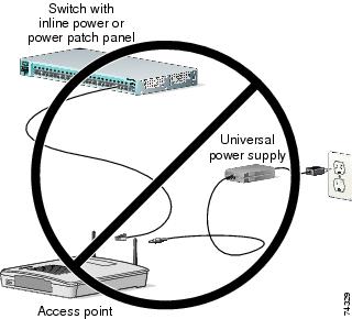
Use Only One Power Option
You cannot provide redundant power to 1130 series access points with both DC power to its power port and inline power from a patch panel or powered switch to the access point Ethernet port. If you apply power to the access point from both sources, the switch or power patch panel might shut down the port to which the access point is connected. Figure 1 shows the power configuration that can shut down the port on the patch panel or powered switch.
Figure 1 Improper Power Configuration Using Two Power Sources
Configuring Power for 1130, 1140, 1240, and 1250 Series Access Points
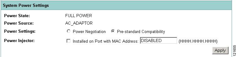
The 1130, 1140, 1240, and 1250 series access points disable the radio interfaces when the connected power source does not provide enough power. Depending on your power source, you might need to enter the power source type in the access point configuration. Use the System Software: System Configuration page on the web-browser interface to select a power option. Figure 2 shows the System Power Settings section of the System Configuration page.
Figure 2 Power Options on the System Software: System Configuration Page
The PoE power status can also be found in the PoE Status section on the network interfaces>network status page on the access point GUI. The status statements can include any of the following:
•
•
•
•
Using the AC Power Adapter
If you use the AC power adapter to provide power to the access point, you do not need to adjust the access point configuration.
Using a Switch Capable of IEEE 802.3af Power Negotiation
If you use a switch to provide PoE to the access point and the switch supports the IEEE 802.3af power negotiation standard, select Power Negotiation on the System Software: System Configuration page.
Using a Switch That Does Not Support IEEE 802.3af Power Negotiation
If you use a switch to provide Power over Ethernet (PoE) to the access point and the switch does not support the IEEE 802.3af power negotiation standard, select Pre-Standard Compatibility on the System Software: System Configuration page.
Using a Power Injector
If you use a power injector to provide power to the access point, select Power Injector on the System Software: System Configuration page, and enter the MAC address of the switch port to which the access point is connected.
1250 Series Power Modes
The 1250 series access point can be powered by either inline power or by an optional AC/DC power adapter. Certain radio configurations may require more power than can be provided by the inline power source. When insufficient inline power is available, you can select several options (based upon your access point radio configuration) as shown in the following table:
2.4-GHz
802.11b
1
N/A
20
20
20
802.11g
1
N/A
17
17
17
802.11n (MCS 0-7)
1
2Disabled
Enabled (default)17
Disabled17
14 (11 per Tx)217
20 (17 per Tx)802.11n (MCS 8-15)
2
N/A
Disabled
14 (11 per Tx)
20 (17 per Tx)
5-GHz802.11a
1
N/A
17
17
17
802.11n (MCS 0-7)
1
2Disabled
Enabled (default)17
Disabled17
20 (17 per Tx)17
20 (17 per Tx)802.11n (MCS 8-15)
2
N/A
Disabled
20 (17 per Tx)
20 (17 per Tx)
1 Maximum transmit power will vary by channel and according to individual country regulations. Refer to the product documentation for specific details.
2 Tx—Transmitter
Antenna Installation
For instructions on the proper installation and grounding of external antennas for 1240 series access points, refer to the National Fire Protection Association's NFPA 70, National Electrical Code, Article 810, and the Canadian Standards Association's Canadian Electrical Code, Section 54.
Warning
1400 Series Bridge
This section contains installation information for the 1400 series bridge.
Default SSID and Distance Settings Change When You Change Role in Radio Network
If the bridge's SSID has not been changed from the default setting and you select Install Automatic Mode as the bridge's role in radio network setting, the SSID automatically changes from tsunami to autoinstall. When you change the role in radio network from Install Automatic Mode to Root or Non-Root, the SSID changes automatically from autoinstall back to tsunami. However, if you change the SSID from its default setting, changing the role in radio network setting does not change the SSID.
In Install Automatic Mode, the default distance setting is 61.5 mi. (99 km). When you change the role in radio network from Install Automatic Mode to Root or Non-Root, the distance setting changes automatically from 61.5 mi. (99 km) to 0 mi. (0 km).
Default Encryption Key 2 Is Set by Bridge
The encryption key in slot 2 is the transmit key by default. If you enable WEP with MIC, use the same WEP key as the transmit key in the same key slot on both root and non root bridges.
Limitation to PAgP Redundancy on Switches Connected by Bridge Links
When two switches configured for Port Aggregation Protocol (PAgP) are connected by redundant wireless bridge links, the PAgP change-over takes at least 30 seconds, which is too slow to maintain TCP sessions from one port to another.
CLI Command power client n Is Not Supported
The bridge does not support the power client n configuration interface command in the web-browser or CLI interfaces. The bridge does not perform any action when you enter this command.
Default Infrastructure SSID
When a VLAN is enabled, the WEP encryption mode and the WEP key are applicable only to a native VLAN. Any SSID configured should have the Infrastructure-SSID parameter enabled for that SSID. With the Infrastructure-SSID parameter enabled, the bridge ensures that a non-native VLAN cannot be assigned to that SSID.
ARP Table Is Corrupted When Multiple BVIs Are Configured
The bridge supports only one bridge virtual interface (BVI). Multiple BVIs should not be configured because the ARP table can be corrupted.
Bridge Power Up LED Colors
During power up, the bridge LEDs display the following color sequences:
1.
2.
3.
4.
5.
6.
7.
8.
a.
b.
c.
9.
10.
11.
12.
Bridge Cannot Detect Simultaneous Image Downloads
Do not attempt to load software images into the bridge from both a Telnet session and a console session simultaneously. The bridge cannot detect that two images are being loaded at the same time. For best results, use the archive download command in the CLI.
Bridge Cannot Detect Invalid Software When Using copy Command
The bridge sometimes cannot detect invalid software images when you load software using the copy command. For best results, use the archive download command in the CLI to load new software.
Telnet Session Sometimes Hangs or Will Not Start During Heavy Traffic
When the bridge is transmitting and receiving heavy traffic, you sometimes cannot start a Telnet session and some existing Telnet sessions halt. However, this behavior is expected because the bridge gives top priority to data traffic and a lower priority to Telnet traffic.
Important Notes
This section describes important information about access points and bridges.
Synchronize IOS Supplicant Clocks and Save Time Setting to NVRAM
An IOS device whose supplicant is configured to perform certificate-based authentication of its network connection may be unable to connect to the network unless you take the following steps.
To make sure that the device supplicant, after a reload but before it has connected to the network, knows approximately what time it is so it can validate the server's certificate, you must configure the supplicant to learn the time from an NTP server, and to write the time to its NVRAM. This is a requirement for any system that runs Cisco IOS release 12.4(21a)JY.
Complete these steps:
Step 1
Example configuration on a system with SNTP, and without a hardware calendar:
Supp(config)#sntp server 10.0.47.1Supp(config)#clock save interval 8Supp(config)#endSupp#write memoryExample on a system with NTP, and with a hardware calendar:
Supp(config)#ntp server 10.0.47.1 iburstSupp(config)#ntp update-calendarSupp(config)#endSupp#write memoryStep 2
Example:
Supp#show sntpSNTP server Stratum Version Last Receive10.0.47.1 3 1 00:00:09 SyncedExample:
Supp#show ntp statusClock is synchronized, stratum 4, reference is 10.95.42.129[ ... ]Step 3
On a system with no hardware calendar:
•
Supp#show clock detail*08:24:30.103 -0700 Thu Apr 15 2010No time sourceOn a system with hardware calendar:
•
Supp#clock update-calendar•
Supp#show calendar
Access Point Creates File When Radar is Detected on a DFS Channel
When an access point detects a radar on a DFS channel, the access point creates a file in its flash memory. The file is based on the 802.11a radio serial number and contains the channel numbers on which the radar is detected. This is an expected behavior and you should not remove this file.
Access Points Send Multicast and Management Frames at Highest Basic Rate
Access points running recent Cisco IOS versions are transmitting multicast and management frames at the highest configured basic rate, and is a situation that could causes reliability problems.
Access points running LWAPP or autonomous IOS should transmit multicast and management frames at the lowest configured basic rate. This is necessary in order to provide for good coverage at the cell's edge, especially for unacknowledged multicast transmissions where multicast wireless transmissions may fail to be received.
Since multicast frames are not retransmitted at the MAC layer, stations at the edge of the cell may fail to receive them successfully. If reliable reception is a goal, then multicasts should be transmitted at a low data rate. If support for high data rate multicasts is required, then it may be useful to shrink the cell size and to disable all lower data rates.
Depending on your specific requirements, you can take the following action:
•
•
LWAPP to Autonomous Conversion Requires Two Reboots
When you convert an 1142 access point from LWAPP mode to autonomous mode, you might need to reboot the unit twice to complete the conversion.
Interpreting the Show Controller Dot11Radio Active Power Level Output
A portion of the output of the show controller dot11radio CLI command displays the active power levels by rate as shown in the example below:
1.0 to 11.0 , 20 dBm, changed due to regulatory maximum6.0 to m15. , 17 dBm, changed due to regulatory maximumm0.-4 to m15.-4, 14 dBm, changed due to regulatory maximumThe -4 in the third line indicates 40-MHz.
Enabling a Crash File for 1250 Series Access Points
A 1250 series access point that is running a Cisco IOS Release prior to (insert Krypton release number here) does not generate a crash log when it crashes. The crash log is disabled so that a crash does not corrupt the flash file system.
New 1250 series access points shipped from the factory contain a new bootloader image that fixes the flash file system after it is corrupted during a crash (without losing files). This new bootloader automatically sets a new CRASH_LOG environment variable to "yes," which enables a crash log to be generated following a crash. Therefore, no user configuration is needed to enable a crash log on new 1250 series access points shipped from the factory.
To enable 1250 series access points in the field to generate a crash log following a crash, install Cisco IOS Release 12.4(10b)JA or later and enter this case-sensitive bootloader CLI command on the access point: set CRASH_LOG yes. When you set this CLI, the access point does not immediately generate a crash log. The log is generated after a crash occurs. After the crash log is generated, enter this command to disable the CRASH_LOG environment variable to minimize the risk of corrupting the flash file system: set CRASH_LOG no.
Low Throughput Seen on 1140 and 1250 Series Access Points with 16 BSSIDs Configured
If your network uses 16 BSSIDs with 1- and 2-Mbps data rates, 1140 and 1250 series access points might experience very low throughput due to high management traffic.
802.11n HT Rates Apply Only to No Encryption or WPA2/AES Encryption
The 802.11n HT rates apply only to no encryption or WPA2/AES encryption. They do not apply to WEP or WPA encryption. If WEP or TKIP encryption is used, 1140 and 1250 series access points and any 802.11n Draft 2.0 clients will not transmit at the HT rates. Legacy rates (802.11a/b/g) will be used for any clients using WEP or TKIP encryption.
Layer 3 Not Supported with NAC for MBSSID
Layer 3 is not supported with NAC for MBSSID in this release.
Change to Default IP Address Behavior
Cisco IOS Releases 12.3(2)JA and later change the default behavior of access points requesting an IP address from a DHCP server:
When you connect a 1130 or 1240 series access point or a 1300 series outdoor access point/bridge with a default configuration to your LAN, the access point requests an IP address from your DHCP server and, if it does not receive an address, continues to send requests indefinitely.
Changes to the Default Configuration—Radios Disabled and No Default SSID
In this release, the radio or radios are disabled by default, and there is no default SSID. You must create an SSID and enable the radio or radios before the access point allows wireless associations from other devices. These changes to the default configuration improve the security of newly installed access points.
Clients Using WPA/WPA2 and Power Save May Fail to Authenticate
Certain clients using WPA/WPA2 key management and power save can take many attempts to authenticate or, in some cases, fail to authenticate. Any SSID defined to use authentication key-management WPA, coupled with clients using power save mode and authenticating using WPA/WPA2 can experience this problem.
A hidden configure level command, dot11 wpa handshake timeout, can be used to increase the timeout between sending the WPA key packets from the default value (100 ms) to a value between 101 and 2000 ms. The command stores its value in the configuration across device reloads.
Default Username and Password Are Cisco
When you open the access point interface, you must enter a username and a password. The default username for administrator login is Cisco, and the default password is Cisco. Both the username and password are case sensitive.
Some Client Devices Cannot Associate When QoS Is Configured
Some wireless client devices, including Dell Axim handhelds and Hewlett-Packard iPaq HX4700 handhelds, cannot associate to an access point when the access point is configured for QoS. To allow these clients to associate, disable QoS on the access point. You can use the QoS Policies page on the access point GUI to disable QoS or enter this command on the CLI:
ap(config-if)#no dot11 qos mode
Some Devices Disassociate When Multiple BSSIDs Are Added or Deleted
Devices on your wireless LAN that are configured to associate to a specific access point based on the access point MAC address (such as client devices, repeaters, hot standby units, or workgroup bridges) might lose their association when you add or delete a multiple BSSID. When you add or delete a multiple BSSID, check the association status of devices configured to associate to a specific access point. If necessary, reconfigure the disassociated device to use the BSSID new MAC address.
Enabling MBSSIDs Without VLANs Disables Radio Interface
If you use the mbssid configuration interface command to enable multiple BSSIDs on a specific radio interface but VLANs are not configured on the access point, the access point disables the radio interface. To re-enable the radio, you must shut down the radio, disable multiple BSSIDs, and re-enable the radio.
This example shows the commands that you use to re-enable the radio:
AP1242AG(config)# interface d1AP1242AG(config-if)# shutAP1242AG(config-if)# no mbssidAP1242AG(config-if)# no shutAfter you re-enable the radio, you can enable VLANs on the access point and enable multiple BSSIDs.
Cannot Set Channel on DFS-Enabled Radios in Some Regulatory Domains
Access points with 5-GHz radios configured at the factory for use in Europe, Singapore, Korea, Japan, Taiwan, and Israel now comply with regulations that require radio devices to use Dynamic Frequency Selection (DFS) to detect radar signals and to avoid interfering with them. You cannot manually set the channel on DFS-enabled radios configured for these regulatory domains.
Cisco 7920 Phones Require Firmware Version 1.09 or Later When Multiple BSSIDs Are Enabled
When multiple BSSIDs are configured on the access point, Cisco 7920 wireless IP phones must run firmware version 1.09 or later.
TKIP and Cisco 7920 IP Phones
When a 7920 phone is associated to a 1250 series access point using Temporal Key Integrity Protocol (TKIP) encryption, the access point might report "TKIP TSC replay detected" and discard the packets transmitted by the phone (CSCsj35039). To work around this issue, perform one of the following:
•
•
GRE Tunnelling Through WLSM Sometimes Requires MTU Setting Adjustments
If client devices on your wireless LAN cannot use certain network applications or cannot browse to Internet sites, you might need to adjust the MTU setting on the client devices or other network devices. For more information, refer to the Tech Note at this URL:
http://www.cisco.com/en/US/tech/tk827/tk369/technologies_tech_note09186a0080093f1f.shtml
TACACS+ and DHCP IP Address Sometimes Locks Out Administrators
When you configure an access point for TACACS+ administration and to receive an IP address from the DHCP server, administrators might be locked out of the access point after it reboots if the administrator does not have a local username and password configured on the access point. This issue does not affect access points configured with a static IP address. Administrators who have been locked out must regain access by resetting the unit to default settings.
Access Points Do Not Support Loopback Interface
You must not configure a loopback interface on the access point.
Caution
Non-Cisco Aironet 802.11g Clients Might Require Firmware Upgrade
Some non-Cisco Aironet 802.11g client devices require a firmware upgrade before they can associate to the 802.11g radio in the access point. If your non-Cisco Aironet 802.11g client device does not associate to the access point, download and install the latest client firmware from the manufacturer's website.
Throughput Option for 802.11g Radio Blocks Association by 802.11b Clients
When you configure the 802.11g access point radio for best throughput, the access point sets all data rates to basic (required). This setting blocks association from 802.11b client devices. The best throughput option appears on the web-browser interface Express Setup and Radio Settings pages and in the speed CLI configuration interface command.
Use Auto for Ethernet Duplex and Speed Settings
We recommend that you use auto, the default setting, for both the speed and duplex settings on the access point Ethernet port. When your access point receives inline power from a switch, any change in the speed or duplex settings that resets the Ethernet link reboots the access point. If the switch port to which the access point is connected is not set to auto, you can change the access point port to half or full to correct a duplex mismatch, and the Ethernet link is not reset. However, if you change from half or full back to auto, the link is reset, and, if your access point receives inline power from a switch, the access point reboots.
Note
Use force-reload Option with archive download-sw Command
When you upgrade access point or bridge system software by entering the archive download-sw command on the CLI, you must use the force-reload option. If the access point or bridge does not reload the flash memory after the upgrade, the pages in the web-browser interface might not reflect the upgrade. This example shows how to upgrade system software by using the archive download-sw command:
AP# archive download-sw /force-reload /overwrite tftp://10.0.0.1/image-nameRadio MAC Address Appears in ACU
When a Cisco Aironet client device associates to an access point running IOS software, the access point MAC address that appears on the Status page in the Aironet Client Utility (ACU) is the MAC address for the access point radio. The MAC address for the access point Ethernet port is printed on the label on the back of the access point.
Radio MAC Address Appears in Access Point Event Log
When a client device roams from an access point (such as access point alpha) to another access point (access point bravo), a message appears in the event log on access point alpha stating that the client roamed to access point bravo. The MAC address that appears in the event message is the MAC address for the radio in access point bravo. The MAC address for the access point Ethernet port is on the label on the back of the access point.
Mask Field on IP Filters Page Behaves the Same As in CLI
In Cisco IOS Release 12.2(8)JA and later, the mask that you enter in the Mask field on the IP Filters page in the access point GUI behaves the same way as a mask that you enter in the CLI. If you enter 255.255.255.255 as the mask, the access point accepts any IP address. If you enter 0.0.0.0, the access point looks for an exact match with the IP address that you entered in the IP Address field.
Repeater Access Points Cannot Be Configured as WDS Access Points
Repeater access points can participate in WDS, but they cannot provide WDS. You cannot configure a repeater access point as a main WDS access point, and if a root access point becomes a repeater in fallback mode, it cannot provide WDS.
Cannot Perform Link Tests on Non-Cisco Aironet Client Devices and on Cisco Aironet 802.11g Client Devices
The link test feature on the web-browser interface does not support non-Cisco Aironet client devices nor Cisco Aironet 802.11g client devices.
Corrupt EAP Packet Sometimes Causes Error Message
During client authentication, the access point sometimes receives a corrupt EAP packet and displays this error message:
Oct  1 09:00:51.642 R: %SYS-2-GETBUF: Bad getbuffer, bytes= 28165
-Process= "Dot11 Dot1x process", ipl= 0, pid= 32
-Traceback= A2F98 3C441C 3C7184 3C604C 3C5E14 3C5430 124DDC
You can ignore this message.
When Cipher Is TKIP Only, Key Management Must Be Enabled
When you configure TKIP-only cipher encryption (not TKIP + WEP 128 or TKIP + WEP 40) on any radio interface or VLAN, every SSID on that radio or VLAN must be set to use WPA or CCKM key management. If you configure TKIP on a radio or VLAN but you do not configure key management on the SSIDs, client authentication fails on the SSIDs.
Cisco CKM Supports Spectralink Phones
Cisco CKM (CCKM) key management is designed to support voice clients that require minimal roaming times. CCKM supports only Spectralink and Cisco 7920 Version 2.0 Wireless Phones. Other voice clients are not supported.
Non-Cisco Aironet Clients Sometimes Fail 802.1x Authentication
Some non-Cisco Aironet client adapters do not perform 802.1x authentication to the access point unless you configure Open authentication with EAP. To allow both Cisco Aironet clients using LEAP and non-Cisco Aironet clients using LEAP to associate using the same SSID, you might need to configure the SSID for both Network EAP authentication and Open authentication with EAP.
Pings and Link Tests Sometimes Fail to Clients with Both Wired and Wireless Network Connections
When you ping or run a link test from an access point to a client device installed in a PC running Microsoft Windows 2000, the ping or link test sometimes fails when the client has both wired and wireless connections to the LAN. Microsoft does not recommend this configuration. For more information, refer to Microsoft Knowledge Base article 157025 at this URL:
http://support.microsoft.com/default.aspx?scid=kb;en-us;157025&Product=win2000
Layer 3 Mobility Not Supported on Repeaters and Workgroup Bridges
Repeater access points and workgroup bridges cannot associate to an SSID configured for Layer 3 mobility. Layer 3 mobility is not supported on repeaters and workgroup bridges.
WLSM Required for Layer 3 Mobility
You must use a Wireless LAN Services Module (WLSM) as your WDS device in order to properly configure Layer 3 mobility. If you enable Layer 3 mobility for an SSID and your WDS device does not support Layer 3 mobility, client devices cannot associate using that SSID.
Caveats
The following sections lists Open Caveats and Resolved Caveats in Cisco IOS Release 12.4(21a)JY. For your convenience in locating caveats in Cisco's Bug Toolkit, the caveat titles listed in this section are drawn directly from the Bug Toolkit database. These caveat titles are not intended to be read as complete sentences because the title field length is limited. In the caveat titles, some truncation of wording or punctuation might be necessary to provide the most complete and concise description. The only modifications made to these titles are as follows:
•
•
•
Note
http://tools.cisco.com/Support/BugToolKit/
To become a registered cisco.com user, go to the following website:
http://tools.cisco.com/RPF/register/register.do
Open Caveats
Table 1 lists caveats that are open in Cisco IOS Release 12.4(21a)JY.
Resolved Caveats
Table 2 lists caveats resolved in Cisco IOS Release 12.4(21a)JY.
If You Need More Information
If you need information about a specific caveat that does not appear in these release notes, you can use the Cisco Bug Toolkit to find select caveats of any severity. Click this URL to browse to the Bug Toolkit:
http://tools.cisco.com/Support/BugToolKit/
(If you request a defect that cannot be displayed, the defect number might not exist, the defect might not yet have a customer-visible description, or the defect might be marked Cisco Confidential.)
Troubleshooting
For the most up-to-date, detailed troubleshooting information, refer to the Cisco TAC website at http://www.cisco.com/cisco/web/support/index.html. If you are a registered user, click Registered users click here to access the entire technical support site. If you are not a registered user, the public public portion of the technical support site displays. Choose a task or information and proceed.
Obtaining Documentation, Obtaining Support, and Security Guidelines
For information on obtaining documentation, obtaining support, providing documentation feedback, security guidelines, and also recommended aliases and general Cisco documents, see the monthly What's New in Cisco Product Documentation, which also lists all new and revised Cisco technical documentation, at:
http://www.cisco.com/en/US/docs/general/whatsnew/whatsnew.html
CCDE, CCENT, CCSI, Cisco Eos, Cisco HealthPresence, Cisco IronPort, the Cisco logo, Cisco Nurse Connect, Cisco Pulse, Cisco SensorBase, Cisco StackPower, Cisco StadiumVision, Cisco TelePresence, Cisco Unified Computing System, Cisco WebEx, DCE, Flip Channels, Flip for Good, Flip Mino, Flipshare (Design), Flip Ultra, Flip Video, Flip Video (Design), Instant Broadband, and Welcome to the Human Network are trademarks; Changing the Way We Work, Live, Play, and Learn, Cisco Capital, Cisco Capital (Design), Cisco:Financed (Stylized), Cisco Store, Flip Gift Card, and One Million Acts of Green are service marks; and Access Registrar, Aironet, AllTouch, AsyncOS, Bringing the Meeting To You, Catalyst, CCDA, CCDP, CCIE, CCIP, CCNA, CCNP, CCSP, CCVP, Cisco, the Cisco Certified Internetwork Expert logo, Cisco IOS, Cisco Lumin, Cisco Nexus, Cisco Press, Cisco Systems, Cisco Systems Capital, the Cisco Systems logo, Cisco Unity, Collaboration Without Limitation, Continuum, EtherFast, EtherSwitch, Event Center, Explorer, Follow Me Browsing, GainMaker, iLYNX, IOS, iPhone, IronPort, the IronPort logo, Laser Link, LightStream, Linksys, MeetingPlace, MeetingPlace Chime Sound, MGX, Networkers, Networking Academy, PCNow, PIX, PowerKEY, PowerPanels, PowerTV, PowerTV (Design), PowerVu, Prisma, ProConnect, ROSA, SenderBase, SMARTnet, Spectrum Expert, StackWise, WebEx, and the WebEx logo are registered trademarks of Cisco Systems, Inc. and/or its affiliates in the United States and certain other countries.
All other trademarks mentioned in this document or website are the property of their respective owners. The use of the word partner does not imply a partnership relationship between Cisco and any other company. (0910R)