-
Cisco 3825 Mobile Wireless Edge Router Software Configuration Guide
-
Preface
-
Overview of the Cisco 3825 Mobile Wireless Edge Router
-
Cisco IOS Software Basics
-
First-Time Configuration
-
Configuring the Cisco 3825 Mobile Wireless Edge Router in a RAN-O Solution with the Command-Line Interface
-
Cisco 3825 Mobile Wireless Edge Router RAN-O Command Reference
-
Configuration Examples
-
 Feedback
Table Of Contents
Ethernet over MPLS—VLAN and Port Mode Configuration
UMTS Only Configuration without IMA
Combined GSM and UMTS Configuration
GSM and UMTS with IMA Configuration
GSM and UMTS with IMA and PVC Routing (HSDPA Offload) Configuration
GSM Only Configuration via Satellite
Configuration Examples
This appendix provides real-world examples of RAN-O configurations.
•
Asymmetric PWE3 Configuration
•
•
•
•
•
•
•
•
•
Note
Overview
The Radio Access Network-Optimization (RAN-O) supports a variety of topology designs based on various Global System for Mobile Communications (GSM) and Universal Mobile Telecommunications System (UMTS) configurations. Here are some common pieces to this topology:
•
•
•
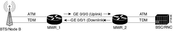
Asymmetric PWE3 Configuration
The following is an example of an Asymmetric PWE3 configuration (see Figure B-1):
Figure B-1 Asymmetric PWE3 Configuration
PE_1
version 12.4service timestamps debug datetime msec localtimeservice timestamps log datetime msec localtimeno service password-encryption!hostname MWR1!boot-start-markerboot-end-marker!card type e1 0 0card type e1 0 1card type e1 0 2card type e1 1 0card type e1 1 1logging buffered 2147483!no aaa new-modelmemory-size iomem 25!redundancymode y-cablestandalone!network-clock-participate slot 1network-clock-participate wic 0network-clock-participate wic 1network-clock-participate wic 2network-clock-participate aim 1network-clock-select 1 E1 1/1/1ipran-alt-interrupt tracingmmi polling-interval 60no mmi auto-configureno mmi pvcmmi snmp-timeout 180ip cef!!no ip domain lookupvlan ifdescr detailmultilink bundle-name authenticatedmpls label protocol ldpmpls traffic-eng tunnelsvpdn enable!!!!!!!!!!!!!!!!!!archivelog config!!controller E1 0/0/0clock source internalcem-group 1 unframed!controller E1 0/0/1clock source internalcem-group 20 unframed!controller E1 0/1/0clock source internalcem-group 12 unframeddescription connected to E1 4/0 of BERT!controller E1 0/1/1clock source internalcem-group 30 unframed!controller E1 0/2/0clock source internalcem-group 8 unframed!controller E1 0/2/1clock source internalcem-group 25 unframed!controller E1 1/0/0mode atm aim 1clock source internal!controller E1 1/0/1mode atm aim 1clock source internal!controller E1 1/1/0mode atm aim 1clock source internal!controller E1 1/1/1!!pseudowire-class mplsencapsulation mplssequencing bothpreferred-path peer 50.0.0.2!pseudowire-class l2tpencapsulation l2tpv3sequencing bothip protocol udpip local interface Loopback50!!class cem cemclasssample-rate 2!class cem cemclass1dejitter-buffer 400!!!!!!!interface Loopback50ip address 50.0.0.1 255.255.255.255!interface CEM0/0/0no ip addresscem 1xconnect 50.0.0.2 1 encapsulation mpls!!interface GigabitEthernet0/0ip address 20.0.0.1 255.0.0.0load-interval 30duplex autospeed autompls label protocol ldpmpls ip!interface CEM0/0/1no ip addresscem 20xconnect 50.0.0.2 2 encapsulation mpls!interface GigabitEthernet0/1ip address 60.0.0.1 255.0.0.0duplex autospeed autompls ip!interface CEM0/1/0no ip addresscem 12xconnect 50.0.0.2 3 encapsulation mpls!!interface CEM0/1/1no ip addresscem 30xconnect 50.0.0.2 4 encapsulation mpls!interface CEM0/2/0no ip addresscem 8xconnect 50.0.0.2 5 encapsulation mpls!!interface CEM0/2/1no ip addresscem 25xconnect 50.0.0.2 6 encapsulation mpls!!interface ATM0/IMA0no ip addressload-interval 30atm mcpt-timers 2000 6000 10000no atm ilmi-keepalivepvc 1/10 l2transportxconnect 50.0.0.2 101 encapsulation mpls sequencing both!pvc 1/11 l2transportxconnect 50.0.0.2 102 pw-class mpls!pvc 1/21 l2transportencapsulation aal0cell-packing 28 mcpt-timer 2xconnect 50.0.0.2 111 encapsulation mpls sequencing both!pvc 1/22 l2transportencapsulation aal0cell-packing 18 mcpt-timer 3xconnect 50.0.0.2 112 encapsulation mpls sequencing both one-to-one!!interface ATM0/IMA0.1 point-to-pointno snmp trap link-statuspvc 1/12 l2transportxconnect 50.0.0.2 103 encapsulation mpls sequencing both!!interface ATM0/IMA0.2 multipointno snmp trap link-statusatm cell-packing 20 mcpt-timer 2xconnect 50.0.0.2 104 pw-class mplspvc 1/13 l2transportencapsulation aal0!pvc 1/14 l2transportencapsulation aal0!!interface ATM0/IMA0.3 point-to-pointno snmp trap link-statuspvc 1/15 l2transportencapsulation aal0cell-packing 10 mcpt-timer 3xconnect 50.0.0.2 105 pw-class mpls!!interface ATM0/IMA0.4 point-to-pointno snmp trap link-statuspvc 1/16 l2transportencapsulation aal0cell-packing 14 mcpt-timer 3xconnect 50.0.0.2 106 pw-class mpls one-to-one!!interface ATM0/IMA0.6 multipointno snmp trap link-statuspvc 1/17 l2transportxconnect 50.0.0.2 107 pw-class mpls!pvc 1/18 l2transportencapsulation aal0xconnect 50.0.0.2 108 encapsulation mpls sequencing both!pvc 1/19 l2transportencapsulation aal0cell-packing 12 mcpt-timer 1xconnect 50.0.0.2 109 encapsulation mpls sequencing both one-to-one!!interface ATM1/0/0no ip addressload-interval 30scrambling-payloadatm mcpt-timers 1000 5000 10000no atm ilmi-keepalivepvc 0/5 l2transportencapsulation aal0cell-packing 10 mcpt-timer 3xconnect 50.0.0.2 10 pw-class l2tp!pvc 0/6 l2transportxconnect 50.0.0.2 20 pw-class l2tp!pvc 0/7 l2transportencapsulation aal0cell-packing 28 mcpt-timer 3xconnect 50.0.0.2 30 encapsulation mpls pw-class mpls one-to-one!pvc 0/8 l2transportxconnect 50.0.0.2 40 pw-class mpls!pvc 0/9 l2transportencapsulation aal0xconnect 50.0.0.2 50 pw-class mpls one-to-one!!interface ATM1/0/0.1 point-to-pointno snmp trap link-statuspvc 0/15 l2transportxconnect 50.0.0.2 13 pw-class mpls!!interface ATM1/0/0.2 multipointno snmp trap link-statusatm cell-packing 2 mcpt-timer 1xconnect 50.0.0.2 12 encapsulation mpls sequencing bothpvc 0/10 l2transportencapsulation aal0!pvc 0/11 l2transportencapsulation aal0!pvc 0/12 l2transportencapsulation aal0!pvc 0/13 l2transportencapsulation aal0!!interface ATM1/0/0.3 point-to-pointno snmp trap link-statuspvc 0/16 l2transportencapsulation aal0xconnect 50.0.0.2 14 encapsulation mpls!!interface ATM1/0/0.4 point-to-pointno snmp trap link-statuspvc 0/17 l2transportencapsulation aal0xconnect 50.0.0.2 15 pw-class mpls one-to-one!!interface ATM1/0/0.6 multipointno snmp trap link-statuspvc 0/26 l2transportxconnect 50.0.0.2 16 pw-class mpls!pvc 0/27 l2transportencapsulation aal0cell-packing 8 mcpt-timer 3xconnect 50.0.0.2 17 pw-class mpls!pvc 0/28 l2transportencapsulation aal0cell-packing 16 mcpt-timer 2xconnect 50.0.0.2 18 pw-class mpls sequencing both one-to-one!!interface ATM1/0/0.7 multipointno snmp trap link-status!interface ATM1/0/1no ip addressscrambling-payloadatm mcpt-timers 1000 5000 10000no atm ilmi-keepaliveatm cell-packing 20 mcpt-timer 2xconnect 50.0.0.2 11 encapsulation mpls sequencing bothpvc 0/21 l2transportencapsulation aal0!pvc 0/22 l2transportencapsulation aal0!pvc 0/23 l2transportencapsulation aal0!!interface ATM1/0/1.1 point-to-pointno snmp trap link-status!interface ATM1/0/1.2 multipointno snmp trap link-status!interface ATM1/1/0no ip addressscrambling-payloadima-group 0no atm ilmi-keepalive!ip route 9.10.0.254 255.255.255.255 9.11.49.254ip route 30.0.0.0 255.0.0.0 GigabitEthernet0/0ip route 50.0.0.2 255.255.255.255 20.0.0.2ip route 50.0.0.5 255.255.255.255 20.0.0.2!!ip http serverno ip http secure-server!!mpls ldp router-id Loopback50 force!!!!!alias exec cpu show proc cpu | i CPUalias exec hist show proc cpu historyalias exec clc clear countersalias exec cmpls clear mpls counters!line con 0exec-timeout 0 0line aux 0line vty 0 4login!endPE_2
version 12.4service timestamps debug datetime msecservice timestamps log datetime msecno service password-encryption!hostname MWR2!boot-start-markerboot-end-marker!card type e1 0 0card type e1 0 1card type e1 0 2card type e1 1 0card type e1 1 1logging buffered 1000000enable password lab!no aaa new-model!redundancymode y-cablestandalone!network-clock-participate slot 1network-clock-participate wic 0network-clock-participate wic 1network-clock-participate wic 2network-clock-participate aim 1network-clock-select 1 E1 0/0/0network-clock-select 2 E1 0/0/1network-clock-select 3 E1 0/1/0network-clock-select 4 E1 0/1/1network-clock-select 5 E1 0/2/0network-clock-select 6 E1 0/2/1ipran-alt-interrupt tracingmmi polling-interval 60no mmi auto-configureno mmi pvcmmi snmp-timeout 180ip cef!!no ip domain lookupvlan ifdescr detailmultilink bundle-name authenticatedmpls label protocol ldpmpls traffic-eng tunnelsvpdn enable!!!!!!!!!!!!!!!!!!archivelog config!!controller E1 0/0/0cem-group 1 unframed!controller E1 0/0/1cem-group 20 unframed!controller E1 0/1/0cem-group 12 unframed!controller E1 0/1/1cem-group 30 unframed!controller E1 0/2/0cem-group 8 unframed!controller E1 0/2/1cem-group 25 unframed!controller E1 1/0/0mode atm aim 1clock source internal!controller E1 1/0/1mode atm aim 1clock source internal!controller E1 1/1/0mode atm aim 1clock source internal!controller E1 1/1/1clock source internal!pseudowire-class mplsencapsulation mplssequencing bothpreferred-path peer 50.0.0.1!pseudowire-class l2tpencapsulation l2tpv3sequencing bothip protocol udpip local interface Loopback50!!class cem test!class cem cemclasssample-rate 2!!!!!!!interface Loopback50ip address 50.0.0.2 255.255.255.255!interface CEM0/0/0no ip addresscem 1xconnect 50.0.0.1 1 encapsulation mpls!!interface GigabitEthernet0/0ip address 30.0.0.1 255.0.0.0duplex autospeed autompls ip!interface CEM0/0/1no ip addresscem 20xconnect 50.0.0.1 2 encapsulation mpls!!interface GigabitEthernet0/1ip address 70.0.0.1 255.0.0.0no ip proxy-arpduplex autospeed autompls ip!interface CEM0/1/0no ip addresscem 12xconnect 50.0.0.1 3 encapsulation mpls!!interface CEM0/1/1no ip addresscem 30xconnect 50.0.0.1 4 encapsulation mpls!!interface CEM0/2/0no ip addresscem 8xconnect 50.0.0.1 5 encapsulation mpls!!interface CEM0/2/1no ip addresscem 25xconnect 50.0.0.1 6 encapsulation mpls!!interface ATM0/IMA0no ip addressload-interval 30atm mcpt-timers 2000 6000 10000no atm ilmi-keepalivepvc 1/10 l2transportxconnect 50.0.0.1 101 encapsulation mpls sequencing both!pvc 1/11 l2transportxconnect 50.0.0.1 102 pw-class mpls!pvc 1/21 l2transportencapsulation aal0xconnect 50.0.0.1 111 encapsulation mpls sequencing both!pvc 1/22 l2transportencapsulation aal0xconnect 50.0.0.1 112 encapsulation mpls sequencing both one-to-one!!interface ATM0/IMA0.1 point-to-pointno snmp trap link-statuspvc 1/12 l2transportxconnect 50.0.0.1 103 encapsulation mpls sequencing both!!interface ATM0/IMA0.2 multipointno snmp trap link-statusatm cell-packing 15 mcpt-timer 3xconnect 50.0.0.1 104 pw-class mplspvc 1/13 l2transportencapsulation aal0!pvc 1/14 l2transportencapsulation aal0!!interface ATM0/IMA0.3 point-to-pointno snmp trap link-statuspvc 1/15 l2transportencapsulation aal0xconnect 50.0.0.1 105 pw-class mpls!!interface ATM0/IMA0.4 point-to-pointno snmp trap link-statuspvc 1/16 l2transportencapsulation aal0cell-packing 7 mcpt-timer 2xconnect 50.0.0.1 106 pw-class mpls one-to-one!!interface ATM0/IMA0.6 multipointno snmp trap link-statuspvc 1/17 l2transportxconnect 50.0.0.1 107 pw-class mpls!pvc 1/18 l2transportencapsulation aal0xconnect 50.0.0.1 108 encapsulation mpls sequencing both!pvc 1/19 l2transportencapsulation aal0cell-packing 9 mcpt-timer 3xconnect 50.0.0.1 109 encapsulation mpls sequencing both one-to-one!!interface ATM1/0/0ip address 1.1.1.2 255.0.0.0load-interval 30scrambling-payloadatm mcpt-timers 1000 5000 10000no atm ilmi-keepalivepvc 0/5 l2transportencapsulation aal0cell-packing 25 mcpt-timer 3xconnect 50.0.0.1 10 pw-class l2tp!pvc 0/6 l2transportxconnect 50.0.0.1 20 pw-class l2tp!pvc 0/7 l2transportencapsulation aal0cell-packing 12 mcpt-timer 2xconnect 50.0.0.1 30 encapsulation mpls pw-class mpls one-to-one!pvc 0/8 l2transportxconnect 50.0.0.1 40 pw-class mpls!pvc 0/9 l2transportencapsulation aal0xconnect 50.0.0.1 50 pw-class mpls one-to-one!pvc 0/99protocol ip 1.1.1.1 broadcastencapsulation aal5snap!!interface ATM1/0/0.1 point-to-pointno snmp trap link-statuspvc 0/15 l2transportxconnect 50.0.0.1 13 pw-class mpls!!interface ATM1/0/0.2 multipointno snmp trap link-statusatm cell-packing 10 mcpt-timer 2xconnect 50.0.0.1 12 encapsulation mpls sequencing bothpvc 0/10 l2transportencapsulation aal0!pvc 0/11 l2transportencapsulation aal0!pvc 0/12 l2transportencapsulation aal0!pvc 0/13 l2transportencapsulation aal0!!interface ATM1/0/0.3 point-to-pointno snmp trap link-statuspvc 0/16 l2transportencapsulation aal0xconnect 50.0.0.1 14 encapsulation mpls!!interface ATM1/0/0.4 point-to-pointno snmp trap link-statuspvc 0/17 l2transportencapsulation aal0xconnect 50.0.0.1 15 pw-class mpls one-to-one!!interface ATM1/0/0.6 multipointno snmp trap link-statuspvc 0/26 l2transportxconnect 50.0.0.1 16 pw-class mpls!pvc 0/27 l2transportencapsulation aal0cell-packing 18 mcpt-timer 3xconnect 50.0.0.1 17 pw-class mpls!pvc 0/28 l2transportencapsulation aal0cell-packing 24 mcpt-timer 2xconnect 50.0.0.1 18 pw-class mpls sequencing both one-to-one!!interface ATM1/0/0.7 multipointno snmp trap link-status!interface ATM1/0/1no ip addressscrambling-payloadatm mcpt-timers 1000 5000 10000no atm ilmi-keepaliveatm cell-packing 20 mcpt-timer 2xconnect 50.0.0.1 11 encapsulation mpls sequencing bothpvc 0/21 l2transportencapsulation aal0!pvc 0/22 l2transportencapsulation aal0!pvc 0/23 l2transportencapsulation aal0!!interface ATM1/1/0no ip addressscrambling-payloadima-group 0no atm ilmi-keepalive!ip route 9.10.0.254 255.255.255.255 9.11.49.254ip route 20.0.0.0 255.0.0.0 GigabitEthernet0/0ip route 50.0.0.1 255.255.255.255 70.0.0.2ip route 50.0.0.5 255.255.255.255 70.0.0.2!!ip http serverno ip http secure-server!!mpls ldp router-id Loopback50 force!!!!!alias exec cpu show proc cpu | i CPUalias exec hist show proc cpu historyalias exec clc clear countersalias exec cmpls clear mpls counters!line con 0exec-timeout 0 0line aux 0line vty 0 4exec-timeout 0 0login!endEthernet over MPLS—VLAN and Port Mode Configuration
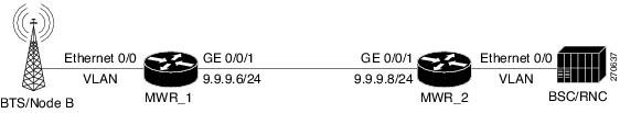
The following is an example of an Ethernet over Multiprotocol Label Switching (MPLS) configuration in VLAN and Port mode (see Figure B-2):
Figure B-2 Ethernet over MPLS—VLAN and Port Mode Configuration
The following represents both a VLAN and port mode in an Ethernet over MPLS configuration:
MWR_1
version 12.4service timestamps debug datetime msecservice timestamps log datetime msecno service password-encryption!hostname mwr-pe1!boot-start-markerboot-end-marker!card type e1 0 1card type e1 0 2card type e1 1 0card type e1 1 1logging buffered 10000000enable password lab!no aaa new-model!redundancymode y-cablestandalone!network-clock-participate slot 1network-clock-participate wic 1network-clock-participate wic 2network-clock-participate aim 1network-clock-select 1 E1 1/1/0mmi polling-interval 60no mmi auto-configureno mmi pvcmmi snmp-timeout 180ip cef!!!!no ip domain lookupvlan ifdescr detailmultilink bundle-name authenticatedmpls label protocol ldpvpdn enable!archivelog confighidekeys!!controller E1 0/0/0clock source internal!controller E1 0/0/1!controller E1 0/1/0!controller E1 0/1/1clock source internal!controller E1 1/0/0clock source internal!controller E1 1/0/1!controller E1 1/1/0!controller E1 1/1/1clock source internal!!!!!!!!interface Loopback0no ip address!interface Loopback1ip address 1.1.1.1 255.255.255.255load-interval 30!interface Loopback101no ip address!! Port modeinterface GigabitEthernet0/0no ip addressload-interval 30speed 1000full-duplexno cdp enablexconnect 2.2.2.2 1 encapsulation mpls!! vlan modeinterface GigabitEthernet0/0.3encapsulation dot1q 3xconnect 2.2.2.2 2 encapsulation mpls!interface GigabitEthernet0/1ip address 9.9.9.6 255.255.255.0load-interval 30speed 1000full-duplexmpls ip!!ip forward-protocol ndip route 2.2.2.2 255.255.255.255 9.9.9.8!ip http serverno ip http secure-server!!snmp-server community public RO!!!control-plane!!!!!!!line con 0exec-timeout 0 0logging synchronousline aux 0line vty 0 4exec-timeout 0 0password lablogin!exception data-corruption buffer truncate!endMRW_2
!version 12.4service timestamps debug datetime msecservice timestamps log datetime msecno service password-encryption!hostname mwr-pe2!boot-start-markerboot-end-marker!card type e1 0 0card type e1 0 1card type e1 0 2card type e1 1 0card type e1 1 1logging buffered 10000000enable password lab!no aaa new-model!redundancymode y-cablestandalone!network-clock-participate slot 1network-clock-participate wic 0network-clock-participate wic 1network-clock-participate wic 2network-clock-participate aim 1network-clock-select 1 E1 0/0/0mmi polling-interval 60no mmi auto-configureno mmi pvcmmi snmp-timeout 180ip arp proxy disableip cef!!!!no ip domain lookupvlan ifdescr detaill2tp-class l2tpmultilink bundle-name authenticatedmpls label protocol ldpmpls ldp session protectionmpls oamecho revision 4vpdn enable!!!!!!!!!!!!!!!!!!!!archivelog confighidekeys!!controller E1 0/0/0!controller E1 0/0/1clock source internal!controller E1 0/1/0!controller E1 0/1/1clock source internal!controller E1 0/2/0clock source internal!controller E1 0/2/1!controller E1 1/0/0clock source internal!controller E1 1/0/1clock source internal!controller E1 1/1/0clock source internal!controller E1 1/1/1clock source internal!!!interface Loopback1ip address 2.2.2.2 255.255.255.255!! port modeinterface GigabitEthernet0/0no ip addressload-interval 30speed 1000full-duplexno cdp enablexconnect 1.1.1.1 1 encapsulation mpls!! vlan modeinterface GigabitEthernet0/0.3encapsulation dot1q 3xconnect 1.1.1.1 2 encapsulation mpls!!interface GigabitEthernet0/1ip address 9.9.9.8 255.255.255.0load-interval 30speed 1000full-duplexmpls ipno cdp enable!ip forward-protocol ndip route 1.1.1.1 255.255.255.255 9.9.9.6!no ip http serverno ip http secure-server!!snmp-server community private RWsnmp-server community public ROsnmp-server ifindex persistsnmp-server trap link ietfno snmp-server sparse-tablessnmp-server queue-length 100snmp-server enable traps snmp authentication linkdown linkup coldstart warmstartsnmp-server enable traps ipranno cdp runroute-map test permit 10match mpls-label!!!mpls ldp router-id Loopback1 force!control-plane!no call rsvp-sync!!!line con 0exec-timeout 0 0logging synchronousline aux 0line vty 0 4exec-timeout 0 0password lablogin!exception data-corruption buffer truncate!endPWE3 over MLPPP Configuration
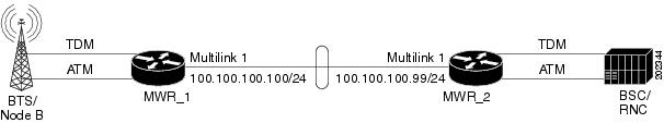
The following is an example of a PWE3 over Multi-link Point-to-Point Protocol (MLPPP) configuration (see Figure B-3):
Figure B-3 PWE3 over MLPPP Configuration
MWR_1
version 12.4service timestamps debug datetime msecservice timestamps log datetime msecno service password-encryption!hostname mwr-pe1!boot-start-markerboot-end-marker!card type e1 0 1card type e1 0 2card type e1 1 0card type e1 1 1logging buffered 10000000enable password lab!no aaa new-model!redundancymode y-cablestandalone!network-clock-participate slot 1network-clock-participate wic 1network-clock-participate wic 2network-clock-participate aim 1network-clock-select 1 E1 1/1/0mmi polling-interval 60no mmi auto-configureno mmi pvcmmi snmp-timeout 180ip cef!!!!no ip domain lookupvlan ifdescr detailmultilink bundle-name authenticatedmpls label protocol ldpvpdn enable!archivelog confighidekeys!!controller E1 0/0/0clock source internalcem-group 0 unframed!controller E1 0/0/1channel-group 0 timeslots 1-31!controller E1 0/1/0channel-group 0 timeslots 1-31!controller E1 0/1/1clock source internalcem-group 3 timeslots 1-31!controller E1 1/0/0mode atm aim 1clock source internal!controller E1 1/0/1channel-group 0 timeslots 1-31!controller E1 1/1/0channel-group 0 timeslots 1-31!controller E1 1/1/1mode atm aim 1clock source internal!!class-map match-any mplsmatch mpls experimental topmost 1!!policy-map llq-policyclass mplspriority percent 99class class-defaultbandwidth percent 1queue-limit 45!!!pseudowire-class class1encapsulation mplssequencing bothmpls experimental 1!!!!!!interface Loopback0no ip address!interface Loopback1ip address 1.1.1.1 255.255.255.255load-interval 30!interface Loopback101no ip address!interface Multilink1000ip address 100.100.100.100 255.255.255.0ip tcp header-compression ietf-formatmpls ipno cdp enableppp pfc local requestppp pfc remote applyppp acfc local requestppp acfc remote applyppp multilinkppp multilink interleaveppp multilink group 1000ppp multilink fragment delay 0 1ppp multilink multiclassmax-reserved-bandwidth 100service-policy output llq-policyhold-queue 50 outip rtp header-compression ietf-format!interface CEM0/0/0no ip addresscem 0xconnect 2.2.2.2 1 pw-class class1!!interface GigabitEthernet0/0ip address 172.18.18.78 255.255.255.0load-interval 30speed 1000full-duplexno cdp enable!interface GigabitEthernet0/1ip address 9.9.9.6 255.255.255.0load-interval 30shutdownspeed 1000full-duplexmpls ip!interface Serial0/0/1:0no ip addressencapsulation pppppp multilinkppp multilink group 1000max-reserved-bandwidth 100!interface Serial0/1/0:0no ip addressencapsulation pppppp multilinkppp multilink group 1000max-reserved-bandwidth 100!interface CEM0/1/1no ip addresscem 3xconnect 2.2.2.2 2 pw-class class1!!interface ATM1/0/0no ip addressscrambling-payloadno atm ilmi-keepalivexconnect 2.2.2.2 3 pw-class class1pvc 0/1 l2transportencapsulation aal0!!interface Serial1/0/1:0no ip addressencapsulation pppppp multilinkppp multilink group 1000max-reserved-bandwidth 100!interface Serial1/1/0:0no ip addressencapsulation pppppp multilinkppp multilink group 1000max-reserved-bandwidth 100!interface ATM1/1/1no ip addressscrambling-payloadno atm ilmi-keepalivepvc 0/1 l2transportencapsulation aal0xconnect 2.2.2.2 4 pw-class class1!pvc 0/2 l2transportencapsulation aal5xconnect 2.2.2.2 5 pw-class class1!pvc 0/5 l2transportencapsulation aal0xconnect 2.2.2.2 6 pw-class class1 one-to-one!!ip forward-protocol ndip route 2.2.2.2 255.255.255.255 Multilink1000!ip http serverno ip http secure-server!!snmp-server community public RO!!!control-plane!!!!!!!line con 0exec-timeout 0 0logging synchronousline aux 0line vty 0 4exec-timeout 0 0password lablogin!exception data-corruption buffer truncate!endMWR_2
!version 12.4service timestamps debug datetime msecservice timestamps log datetime msecno service password-encryption!hostname mwr-pe2!boot-start-markerboot-end-marker!card type e1 0 0card type e1 0 1card type e1 0 2card type e1 1 0card type e1 1 1logging buffered 10000000enable password lab!no aaa new-model!redundancymode y-cablestandalone!network-clock-participate slot 1network-clock-participate wic 0network-clock-participate wic 1network-clock-participate wic 2network-clock-participate aim 1network-clock-select 1 E1 0/0/0mmi polling-interval 60no mmi auto-configureno mmi pvcmmi snmp-timeout 180ip arp proxy disableip cef!!!!no ip domain lookupip host bizarre 64.102.16.25vlan ifdescr detaill2tp-class l2tpmultilink bundle-name authenticatedmpls label protocol ldpmpls ldp session protectionmpls oamecho revision 4vpdn enable!!!!!!!!!!!!!!!!!!!!archivelog confighidekeys!!controller E1 0/0/0cem-group 0 timeslots 1-31!controller E1 0/0/1clock source internalcem-group 1 unframed!controller E1 0/1/0!controller E1 0/1/1clock source internalchannel-group 0 timeslots 1-31!controller E1 0/2/0clock source internalchannel-group 0 timeslots 1-31!controller E1 0/2/1!controller E1 1/0/0mode atm aim 1clock source internal!controller E1 1/0/1clock source internalchannel-group 0 timeslots 1-31!controller E1 1/1/0clock source internalchannel-group 0 timeslots 1-31!controller E1 1/1/1mode atm aim 1clock source internal!!class-map match-any mplsmatch mpls experimental topmost 1!!policy-map llq-policyclass mplspriority percent 99class class-defaultbandwidth percent 1queue-limit 45!pseudowire-class class1encapsulation mplssequencing bothmpls experimental 1!!!!!!!interface Loopback1ip address 2.2.2.2 255.255.255.255!!interface Multilink1000ip address 100.100.100.99 255.255.255.0ip tcp header-compression ietf-formatmpls ipno cdp enableppp pfc local requestppp pfc remote applyppp acfc local requestppp acfc remote applyppp multilinkppp multilink interleaveppp multilink group 1000ppp multilink fragment delay 0 1ppp multilink multiclassmax-reserved-bandwidth 100service-policy output llq-policyhold-queue 50 outip rtp header-compression ietf-format!interface CEM0/0/0no ip addresscem 0xconnect 1.1.1.1 2 pw-class class1!!interface GigabitEthernet0/0ip address 172.18.18.179 255.255.255.0load-interval 30speed 1000full-duplexmpls mtu 2000no cdp enable!interface CEM0/0/1no ip addresscem 1xconnect 1.1.1.1 1 pw-class class1!!interface GigabitEthernet0/1ip address 9.9.9.8 255.255.255.0load-interval 30shutdownspeed 1000full-duplexmpls ipno cdp enable!interface Serial0/1/1:0no ip addressencapsulation pppppp multilinkppp multilink group 1000max-reserved-bandwidth 100!interface Serial0/2/0:0no ip addressencapsulation pppppp multilinkppp multilink group 1000max-reserved-bandwidth 100!interface ATM1/0/0no ip addressscrambling-payloadno atm ilmi-keepalivexconnect 1.1.1.1 3 pw-class class1pvc 0/1 l2transportencapsulation aal0!!interface Serial1/0/1:0no ip addressencapsulation pppppp multilinkppp multilink group 1000max-reserved-bandwidth 100!interface Serial1/1/0:0no ip addressencapsulation pppppp multilinkppp multilink group 1000max-reserved-bandwidth 100!interface ATM1/1/1no ip addressscrambling-payloadno atm ilmi-keepalivepvc 0/1 l2transportencapsulation aal0xconnect 1.1.1.1 4 pw-class class1!pvc 0/2 l2transportencapsulation aal5xconnect 1.1.1.1 5 pw-class class1!pvc 0/5 l2transportencapsulation aal0xconnect 1.1.1.1 6 pw-class class1 one-to-one!!ip forward-protocol ndip route 1.1.1.1 255.255.255.255 Multilink1000!no ip http serverno ip http secure-server!!snmp-server community private RWsnmp-server community public ROsnmp-server ifindex persistsnmp-server trap link ietfno snmp-server sparse-tablessnmp-server queue-length 100snmp-server enable traps snmp authentication linkdown linkup coldstart warmstartsnmp-server enable traps ipranno cdp runroute-map test permit 10match mpls-label!!!mpls ldp router-id Loopback1 force!control-plane!no call rsvp-sync!!!line con 0exec-timeout 0 0logging synchronousline aux 0line vty 0 4exec-timeout 0 0password lablogin!exception data-corruption buffer truncate!endPWE3 Redundancy Configuration
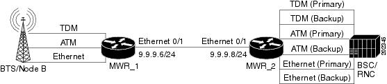
The following is an example of a PWE3 Redundancy configuration (see Figure B-4):
Figure B-4 PWE3 Redundancy Configuration
MWR_1
version 12.4service timestamps debug datetime msecservice timestamps log datetime msecno service password-encryption!hostname mwr-pe1!boot-start-markerboot-end-marker!card type e1 0 1card type e1 0 2card type e1 1 0card type e1 1 1logging buffered 10000000enable password lab!no aaa new-model!redundancymode y-cablestandalone!network-clock-participate slot 1network-clock-participate wic 1network-clock-participate wic 2network-clock-participate aim 1network-clock-select 1 E1 1/1/0mmi polling-interval 60no mmi auto-configureno mmi pvcmmi snmp-timeout 180ip cef!!!!no ip domain lookupvlan ifdescr detailmultilink bundle-name authenticatedmpls label protocol ldpvpdn enable!archivelog confighidekeys!!controller E1 0/0/0clock source internalcem-group 0 unframed!controller E1 0/0/1!controller E1 0/1/0!controller E1 0/1/1clock source internal!controller E1 1/0/0mode atm aim 1clock source internal!controller E1 1/0/1!controller E1 1/1/0!controller E1 1/1/1clock source internal!interface cem0/0/0cem 0xconnect 2.2.2.2 1 encapsulation mplsbackup peer 2.2.2.2 2backup delay 20 20!interface ATM01/0/0no ip addressscrambling-payloadno atm ilmi-keepalivexconnect 2.2.2.2 3 encapsulation mplsbackup peer 2.2.2.2 4backup delay 20 20pvc 0/1 l2transportencapsulation aal0!interface Loopback0no ip address!interface Loopback1ip address 1.1.1.1 255.255.255.255load-interval 30!interface Loopback101no ip address!!!!interface GigabitEthernet0/0.3encapsulation dot1q 3xconnect 2.2.2.2 5 encapsulation mplsbackup peer 2.2.2.2 6backup delay 20 20!interface GigabitEthernet0/1ip address 9.9.9.6 255.255.255.0load-interval 30speed 1000full-duplexmpls ip!!ip forward-protocol ndip route 2.2.2.2 255.255.255.255 9.9.9.8!ip http serverno ip http secure-server!!snmp-server community public RO!!!control-plane!!!!!!!line con 0exec-timeout 0 0logging synchronousline aux 0line vty 0 4exec-timeout 0 0password lablogin!exception data-corruption buffer truncate!endMWR_2
!version 12.4service timestamps debug datetime msecservice timestamps log datetime msecno service password-encryption!hostname mwr-pe2!boot-start-markerboot-end-marker!card type e1 0 0card type e1 0 1card type e1 0 2card type e1 1 0card type e1 1 1logging buffered 10000000enable password lab!no aaa new-model!redundancymode y-cablestandalone!network-clock-participate slot 1network-clock-participate wic 0network-clock-participate wic 1network-clock-participate wic 2network-clock-participate aim 1network-clock-select 1 E1 0/0/0mmi polling-interval 60no mmi auto-configureno mmi pvcmmi snmp-timeout 180ip arp proxy disableip cef!!!!no ip domain lookupvlan ifdescr detaill2tp-class l2tpmultilink bundle-name authenticatedmpls label protocol ldpmpls ldp session protectionmpls oamecho revision 4vpdn enable!!!!archivelog confighidekeys!!controller E1 0/0/0cem-group 0 unframed!controller E1 0/0/1clock source internalcem-group 0 unframed!controller E1 0/1/0!controller E1 0/1/1clock source internal!controller E1 0/2/0clock source internal!controller E1 0/2/1!controller E1 1/0/0mode atm aim 1clock source internal!controller E1 1/0/1clock source internal!controller E1 1/1/0clock source internal!controller E1 1/1/1mode atm aim 1clock source internal!! Primaryinterface cem0/0/0cem 0xconnect 1.1.1.1 1 encapsulation mpls!! Backupinterface cem0/0/1cem 0xconnect 1.1.1.1 2 encapsulation mpls!! Primaryinterface ATM1/0/0no ip addressscrambling-payloadno atm ilmi-keepalivexconnect 1.1.1.1 3 encapsulation mplspvc 0/1 l2transportencapsulation aal0!! Backupinterface ATM1/1/1no ip addressscrambling-payloadno atm ilmi-keepalivexconnect 1.1.1.1 4 encapsulation mplspvc 0/1 l2transportencapsulation aal0!!interface Loopback1ip address 2.2.2.2 255.255.255.255!! Primaryinterface GigabitEthernet0/0.3encapsulation dot1q 3xconnect 1.1.1.1 5 encapsulation mpls!! Backupinterface GigabitEthernet0/0.4encapsulation dot1q 4xconnect 1.1.1.1 6 encapsulation mpls!!!interface GigabitEthernet0/1ip address 9.9.9.8 255.255.255.0load-interval 30speed 1000full-duplexmpls ipno cdp enable!ip forward-protocol ndip route 1.1.1.1 255.255.255.255 9.9.9.6!no ip http serverno ip http secure-server!!snmp-server community private RWsnmp-server community public ROsnmp-server ifindex persistsnmp-server trap link ietfno snmp-server sparse-tablessnmp-server queue-length 100snmp-server enable traps snmp authentication linkdown linkup coldstart warmstartsnmp-server enable traps ipranno cdp runroute-map test permit 10match mpls-label!!!mpls ldp router-id Loopback1 force!control-plane!no call rsvp-sync!!!line con 0exec-timeout 0 0logging synchronousline aux 0line vty 0 4exec-timeout 0 0password lablogin!exception data-corruption buffer truncate!endTDM over MPLS Configuration
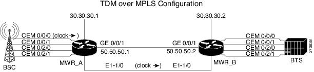
The following is an example of a time-division multiplexing (TDM) over MPLS configuration (see Figure B-5):
Figure B-5 TDM over MPLS Configuration
MWR_A
!version 12.4service timestamps debug datetime msec localtime show-timezoneservice timestamps log datetime msec localtime show-timezoneno service password-encryptionservice internal!hostname mwr_A!boot-start-markerboot-end-marker!card type e1 0 0card type t1 0 2enable password xxx!no aaa new-modelclock timezone est -5!redundancymode y-cablestandalone!network-clock-participate slot 1network-clock-participate wic 0network-clock-participate wic 2network-clock-select 1 E1 0/0/0mmi polling-interval 60no mmi auto-configureno mmi pvcmmi snmp-timeout 180ip cef!controller E1 0/0/0cem-group 0 timeslots 1-31description E1 CESoPSN example!controller E1 0/0/1clock source internalcem-group 1 unframeddescription E1 SATOP example!controller T1 0/2/0framing esfclock source internallinecode b8zscem-group 4 unframeddescription T1 SATOP example!controller T1 0/2/1framing esfclock source internallinecode b8zscem-group 5 timeslots 1-24description T1 CESoPSN example!controller E1 1/0/0clock source internal!controller E1 1/0/1!interface Loopback0ip address 30.30.30.1 255.255.255.255!interface CEM0/0/0no ip addresscem 0xconnect 30.30.30.2 300 encapsulation mpls!!interface GigabitEthernet0/0no ip addressno ip proxy-arpduplex autospeed autono cdp enable!interface CEM0/0/1no ip addresscem 1xconnect 30.30.30.2 301 encapsulation mpls!!interface GigabitEthernet0/1ip address 50.50.50.1 255.255.255.0no ip proxy-arpduplex autospeed autompls ipno cdp enable!interface CEM0/2/0no ip addresscem 4xconnect 30.30.30.2 304 encapsulation mpls!!interface CEM0/2/1no ip addresscem 5xconnect 30.30.30.2 305 encapsulation mpls!!no ip classlessip route 30.30.30.2 255.255.255.255 50.50.50.2!no ip http serverno ip http secure-server!line con 0password xxxloginline aux 0password xxxloginno execline vty 0 4password xxxlogin!endMWR_B
!version 12.4service timestamps debug datetime msec localtime show-timezoneservice timestamps log datetime msec localtime show-timezoneno service password-encryptionservice internal!hostname mwr_B!boot-start-markerboot-end-marker!card type e1 0 0card type t1 0 2enable password xxx!no aaa new-modelclock timezone est -5!redundancymode y-cablestandalone!network-clock-participate slot 1network-clock-participate wic 0network-clock-participate wic 1network-clock-participate wic 2network-clock-select 1 E1 1/0/0mmi polling-interval 60no mmi auto-configureno mmi pvcmmi snmp-timeout 180ip cef!controller E1 0/0/0clock source internalcem-group 0 timeslots 1-31description E1 CESoPSN example!controller E1 0/0/1clock source internalcem-group 1 unframeddescription E1 SATOP example!controller T1 0/2/0framing esfclock source internallinecode b8zscem-group 4 unframeddescription T1 SATOP example!controller T1 0/2/1framing esfclock source internallinecode b8zscem-group 5 timeslots 1-24description T1 CESoPSN example!controller E1 1/0/0!controller E1 1/0/1!interface Loopback0ip address 30.30.30.2 255.255.255.255!interface CEM0/0/0no ip addresscem 0xconnect 30.30.30.1 300 encapsulation mpls!!interface GigabitEthernet0/0no ip addressno ip proxy-arpduplex autospeed autono cdp enable!interface CEM0/0/1no ip addresscem 1xconnect 30.30.30.1 301 encapsulation mpls!!interface GigabitEthernet0/1ip address 50.50.50.2 255.255.255.0no ip proxy-arpduplex autospeed autompls ipno cdp enable!interface CEM0/2/0no ip addresscem 4xconnect 30.30.30.1 304 encapsulation mpls!!interface CEM0/2/1no ip addresscem 5xconnect 30.30.30.1 305 encapsulation mpls!!no ip classlessip route 30.30.30.2 255.255.255.255 50.50.50.1!no ip http serverno ip http secure-server!line con 0password xxxloginline aux 0password xxxloginno execline vty 0 4password xxxlogin!endATM over MPLS Configurations
The illustration below configures an ATM port mode pseudowire (PW) on interface ATM 0/0/0, ATM AAL5 SDU mode PW on ATM0/0/1 PVC 0/100, ATM N:1 VCC cell mode PW on ATM0/0/1 PVC 0/101, multiple PVCs N:1 VCC cell mode PW on ATM 0/0/1.1, and ATM 1:1 VCC cell mode PW on ATM0/0/1 PVC 0/102. It also configures Cell-Packing for port mode PWs, VCC cell-relay mode PWs and PVC mapping for ATM0/0/1.1 N:1 VCC cell relay PWs (see Figure B-6).
Figure B-6 ATM over MPLS Configuration
MWR_A
!version 12.4service timestamps debug datetime msecservice timestamps log datetime msecno service password-encryption!hostname mwr_A!boot-start-markerboot-end-marker!card type e1 0 0card type e1 0 1card type e1 0 2card type e1 1 0logging buffered 4096enable password lab!no aaa new-modelmemory-size iomem 25!redundancymode y-cablestandalone!network-clock-participate slot 1network-clock-participate wic 0network-clock-participate wic 1network-clock-participate wic 2network-clock-participate aim 1network-clock-select 1 E1 1/0/0mmi polling-interval 60no mmi auto-configureno mmi pvcmmi snmp-timeout 180ip cef!!no ip domain lookupip domain name cisco.commultilink bundle-name authenticatedmpls label range 100 100000 static 16 99vpdn enable!!!!!!!!!!!!!!!!!!archivelog config!!controller E1 0/0/0mode atm aim 1clock source internal!controller E1 0/0/1mode atm aim 1clock source internal!controller E1 0/1/0mode atm aim 1clock source internal!controller E1 0/1/1mode atm aim 1clock source internal!controller E1 0/2/0!controller E1 0/2/1!controller E1 1/0/0!controller E1 1/0/1!pseudowire-class mpls-exp-5encapsulation mplssequencing bothmpls experimental 5!!!!!!!!interface Loopback0ip address 88.88.88.88 255.255.255.255!interface ATM0/0/0no ip addressscrambling-payloadatm mcpt-timers 1000 2000 3000no atm ilmi-keepaliveatm cell-packing 28 mcpt-timer 3xconnect 99.99.99.99 100 encapsulation mpls sequencing bothpvc 1/35 l2transportencapsulation aal0!pvc 1/36 l2transportencapsulation aal0!pvc 1/37 l2transportencapsulation aal0!!interface GigabitEthernet0/0ip address 172.18.52.129 255.255.255.0duplex autospeed autono keepalive!interface ATM0/0/1no ip addressload-interval 30scrambling-payloadatm mcpt-timers 1000 2000 3000no atm ilmi-keepalivepvc 0/10!pvc 0/100 l2transportencapsulation aal5xconnect 99.99.99.99 1100 encapsulation mpls sequencing both!pvc 0/101 l2transportencapsulation aal0cell-packing 28 mcpt-timer 3xconnect 99.99.99.99 1101 encapsulation mpls sequencing both!pvc 0/102 l2transportencapsulation aal0cell-packing 28 mcpt-timer 3xconnect 99.99.99.99 1102 encapsulation mpls sequencing both one-to-one!pvc 0/103 l2transportencapsulation aal0cell-packing 28 mcpt-timer 3xconnect 99.99.99.99 1103 pw-class mpls-exp-5!!interface ATM0/0/1.1 multipointno snmp trap link-statusatm cell-packing 28 mcpt-timer 3xconnect 99.99.99.99 1200 encapsulation mpls sequencing bothpvc 1/35 l2transportencapsulation aal0pw-pvc 2/135!pvc 1/36 l2transportencapsulation aal0pw-pvc 2/136!pvc 1/37 l2transportencapsulation aal0pw-pvc 2/137!!interface GigabitEthernet0/1description interface to 7600 fas 3/5ip address 2.2.2.2 255.255.255.0duplex autospeed autompls ipno keepalive!interface ATM0/1/0no ip addressscrambling-payloadno atm ilmi-keepalive!interface ATM0/1/1no ip addressscrambling-payloadno atm ilmi-keepalive!interface ATM0/IMA1no ip addressno atm ilmi-keepalive!ip route 0.0.0.0 0.0.0.0 172.18.52.1ip route 99.99.99.99 255.255.255.255 2.2.2.3!!ip http serverno ip http secure-server!!mpls ldp router-id Loopback0disable-eadi!!!!line con 0exec-timeout 0 0line aux 0line vty 0 4exec-timeout 0 0privilege level 15password labno login!endMWR_B
!version 12.4service timestamps debug datetime msecservice timestamps log datetime msecno service password-encryption!hostname mwr_B!boot-start-markerboot-end-marker!card type e1 0 0card type e1 0 1logging buffered 4096enable password lab!no aaa new-model!redundancymode y-cablestandalone!network-clock-participate wic 0network-clock-participate wic 1network-clock-participate wic 2network-clock-participate aim 1network-clock-select 1 E1 0/0/0mmi polling-interval 60no mmi auto-configureno mmi pvcmmi snmp-timeout 180ip cef!!no ip domain lookupip domain name cisco.commultilink bundle-name authenticatedmpls label protocol ldpvpdn enable!!!!!!!!!!!!!!!!!!archivelog config!!controller E1 0/0/0mode atm aim 1!controller E1 0/0/1mode atm aim 1!controller E1 0/1/0mode atm aim 1!controller E1 0/1/1mode atm aim 1!controller E1 0/2/0!controller E1 0/2/1!pseudowire-class mpls-exp-5encapsulation mplssequencing bothmpls experimental 5!!!!!!!!interface Loopback0ip address 99.99.99.99 255.255.255.255!interface ATM0/0/0no ip addressscrambling-payloadatm mcpt-timers 1000 2000 3000no atm ilmi-keepaliveatm cell-packing 28 mcpt-timer 3xconnect 88.88.88.88 100 encapsulation mpls sequencing bothpvc 1/35 l2transportencapsulation aal0!pvc 1/36 l2transportencapsulation aal0!pvc 1/37 l2transportencapsulation aal0!!interface GigabitEthernet0/0ip address 172.18.52.130 255.255.255.0duplex autospeed autokeepalive 1!interface ATM0/0/1no ip addressscrambling-payloadatm mcpt-timers 1000 2000 3000no atm ilmi-keepalivepvc 0/2!pvc 0/100 l2transportencapsulation aal5xconnect 88.88.88.88 1100 encapsulation mpls sequencing both!pvc 0/101 l2transportencapsulation aal0cell-packing 28 mcpt-timer 3xconnect 88.88.88.88 1101 encapsulation mpls sequencing both!pvc 0/102 l2transportencapsulation aal0cell-packing 28 mcpt-timer 3xconnect 88.88.88.88 1102 encapsulation mpls sequencing both one-to-one!pvc 0/103 l2transportencapsulation aal0cell-packing 28 mcpt-timer 3xconnect 88.88.88.88 1103 pw-class mpls-exp-5!!interface ATM0/0/1.1 multipointno snmp trap link-statusatm cell-packing 28 mcpt-timer 3xconnect 88.88.88.88 1200 encapsulation mpls sequencing bothpvc 2/135 l2transportencapsulation aal0!pvc 2/136 l2transportencapsulation aal0!pvc 2/137 l2transportencapsulation aal0!!interface GigabitEthernet0/1ip address 2.2.2.3 255.255.255.0duplex autospeed autompls ip!interface ATM0/1/0no ip addressscrambling-payloadima-group 0no atm ilmi-keepalive!interface ATM0/1/1no ip addressscrambling-payloadima-group 0no atm ilmi-keepalive!ip route 0.0.0.0 0.0.0.0 172.18.52.1ip route 88.88.88.88 255.255.255.255 2.2.2.2!!ip http serverno ip http secure-server!!mpls ldp router-id Loopback0!!!!!line con 0exec-timeout 0 0line aux 0line vty 0 4exec-timeout 0 0password lablogin!endATM over L2TPv3 Configuration
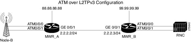
The illustration below configures an ATM port mode PW on interface ATM 0/0/0, ATM AAL5 SDU mode PW on ATM0/0/1 PVC 0/100, ATM N:1 VCC cell mode PW on ATM0/0/1 PVC 0/101, and multiple PVCs N:1 VCC cell mode PW on ATM 0/0/1.1. It also configures Cell-Packing for port mode PWs, VCC cell-relay mode PWs and PVC mapping for ATM0/0/1.1 N:1 VCC cell relay PWs (see Figure B-7).
Figure B-7 ATM over L2TPv3 Configuration
MWR_A
!version 12.4service timestamps debug datetime msecservice timestamps log datetime msecno service password-encryption!hostname mwr_A!boot-start-markerboot-end-marker!card type e1 0 0card type e1 0 1card type e1 0 2card type e1 1 0logging buffered 4096enable password lab!no aaa new-modelmemory-size iomem 25!redundancymode y-cablestandalone!network-clock-participate slot 1network-clock-participate wic 0network-clock-participate wic 1network-clock-participate wic 2network-clock-participate aim 1network-clock-select 1 E1 1/0/0mmi polling-interval 60no mmi auto-configureno mmi pvcmmi snmp-timeout 180ip cef!!no ip domain lookupip domain name cisco.commultilink bundle-name authenticatedmpls label range 100 100000 static 16 99vpdn enable!!!!!!!!!!!!!!!!!!archivelog config!!controller E1 0/0/0mode atm aim 1clock source internal!controller E1 0/0/1mode atm aim 1clock source internal!controller E1 0/1/0mode atm aim 1clock source internal!controller E1 0/1/1mode atm aim 1clock source internal!controller E1 0/2/0!controller E1 0/2/1!controller E1 1/0/0!controller E1 1/0/1!pseudowire-class l2tpencapsulation l2tpv3sequencing bothip local interface Loopback0ip tos value 15!!!!!!!!interface Loopback0ip address 88.88.88.88 255.255.255.255!interface ATM0/0/0no ip addressscrambling-payloadatm mcpt-timers 1000 2000 3000no atm ilmi-keepaliveatm cell-packing 28 mcpt-timer 3xconnect 99.99.99.99 100 pw-class l2tppvc 1/35 l2transportencapsulation aal0!pvc 1/36 l2transportencapsulation aal0!pvc 1/37 l2transportencapsulation aal0!!interface GigabitEthernet0/0ip address 172.18.52.129 255.255.255.0duplex autospeed autono keepalive!interface ATM0/0/1no ip addressload-interval 30scrambling-payloadatm mcpt-timers 1000 2000 3000no atm ilmi-keepalivepvc 0/100 l2transportencapsulation aal5xconnect 99.99.99.99 1100 pw-class l2tp!pvc 0/101 l2transportencapsulation aal0cell-packing 28 mcpt-timer 3xconnect 99.99.99.99 1101 pw-class l2tp!!interface ATM0/0/1.1 multipointno snmp trap link-statusatm cell-packing 28 mcpt-timer 3xconnect 99.99.99.99 1200 pw-class l2tppvc 1/35 l2transportencapsulation aal0pw-pvc 2/135!pvc 1/36 l2transportencapsulation aal0pw-pvc 2/136!pvc 1/37 l2transportencapsulation aal0pw-pvc 2/137!!interface GigabitEthernet0/1description interface to 7600 fas 3/5ip address 2.2.2.2 255.255.255.0duplex autospeed autompls ipno keepalive!interface ATM0/1/0no ip addressscrambling-payloadno atm ilmi-keepalive!interface ATM0/1/1no ip addressscrambling-payloadno atm ilmi-keepalive!interface ATM0/IMA1no ip addressno atm ilmi-keepalive!ip route 0.0.0.0 0.0.0.0 172.18.52.1ip route 99.99.99.99 255.255.255.255 2.2.2.3!!ip http serverno ip http secure-server!!mpls ldp router-id Loopback0disable-eadi!!!line con 0exec-timeout 0 0line aux 0line vty 0 4exec-timeout 0 0privilege level 15password labno login!endMWR_B
!version 12.4service timestamps debug datetime msecservice timestamps log datetime msecno service password-encryption!hostname mwr_B!boot-start-markerboot-end-marker!card type e1 0 0card type e1 0 1logging buffered 4096enable password lab!no aaa new-model!redundancymode y-cablestandalone!network-clock-participate wic 0network-clock-participate wic 1network-clock-participate wic 2network-clock-participate aim 1network-clock-select 1 E1 0/0/0mmi polling-interval 60no mmi auto-configureno mmi pvcmmi snmp-timeout 180ip cef!!no ip domain lookupip domain name cisco.commultilink bundle-name authenticatedmpls label protocol ldpvpdn enable!!!!!!!!!!!!!!!!!!archivelog config!!controller E1 0/0/0mode atm aim 1!controller E1 0/0/1mode atm aim 1!controller E1 0/1/0mode atm aim 1!controller E1 0/1/1mode atm aim 1!controller E1 0/2/0!controller E1 0/2/1!pseudowire-class l2tpencapsulation l2tpv3sequencing bothip local interface Loopback0ip tos value 15!!!!!!!!interface Loopback0ip address 99.99.99.99 255.255.255.255!interface ATM0/0/0no ip addressscrambling-payloadatm mcpt-timers 1000 2000 3000no atm ilmi-keepaliveatm cell-packing 28 mcpt-timer 3xconnect 88.88.88.88 100 pw-class l2tppvc 1/35 l2transportencapsulation aal0!pvc 1/36 l2transportencapsulation aal0!pvc 1/37 l2transportencapsulation aal0!!interface GigabitEthernet0/0ip address 172.18.52.130 255.255.255.0duplex autospeed autokeepalive 1!interface ATM0/0/1no ip addressscrambling-payloadatm mcpt-timers 1000 2000 3000no atm ilmi-keepalivepvc 0/2!pvc 0/100 l2transportencapsulation aal5xconnect 88.88.88.88 1100 pw-class l2tp!pvc 0/101 l2transportencapsulation aal0cell-packing 28 mcpt-timer 3xconnect 88.88.88.88 1101 pw-class l2tp!!interface ATM0/0/1.1 multipointno snmp trap link-statusatm cell-packing 28 mcpt-timer 3xconnect 88.88.88.88 1200 pw-class l2tppvc 2/135 l2transportencapsulation aal0!pvc 2/136 l2transportencapsulation aal0!pvc 2/137 l2transportencapsulation aal0!!interface GigabitEthernet0/1ip address 2.2.2.3 255.255.255.0duplex autospeed autompls ip!interface ATM0/1/0no ip addressscrambling-payloadima-group 0no atm ilmi-keepalive!interface ATM0/1/1no ip addressscrambling-payloadima-group 0no atm ilmi-keepalive!ip route 0.0.0.0 0.0.0.0 172.18.52.1ip route 88.88.88.88 255.255.255.255 2.2.2.2!!ip http serverno ip http secure-server!!mpls ldp router-id Loopback0!!!!!line con 0exec-timeout 0 0line aux 0line vty 0 4exec-timeout 0 0password lablogin!endGSM Only Configuration
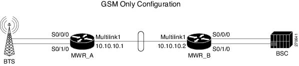
The standard GSM topology includes one or more shorthaul interface connections from the BTS to a RAN-O device via separate T1/E1 connections. The RAN-O devices are connected back-to-back using an MLPPP backhaul connection (two or more T1/E1 connections). At the BSC side, the RAN-O to BSC connectivity is exactly like the BTS to RAN-O connections. In this scenario, only GSM traffic traverses the topology (see Figure B-8).
Figure B-8 GSM Only Configuration
MWR_A
!card type E1 0 0card type E1 0 1!!redundancymode y-cablestandalone!network-clock-participate wic 0network-clock-participate wic 1network-clock-participate aim 1network-clock-select 1 E1 0/0/1!ipran-mib snmp-access inBandipran-mib location cellSite!!controller E1 0/0/0framing NO-CRC4clock source internalchannel-group 0 timeslots 1-31!controller E1 0/0/1channel-group 0 timeslots 1-31!controller E1 0/1/0framing NO-CRC4clock source internalchannel-group 0 timeslots 1-31!!class-map match-any llq-classmatch ip dscp ef!!policy-map llq-policyclass llq-classpriority percent 99class class-defaultbandwidth remaining percent 1queue-limit 45!interface Multilink1ip address 10.10.10.1 255.255.255.252load-interval 30no keepaliveno cdp enableppp pfc local requestppp pfc remote applyppp acfc local requestppp acfc remote applyppp multilinkppp multilink interleaveppp multilink group 1ppp multilink fragment delay 0 1ppp multilink multiclassmax-reserved-bandwidth 100service-policy output llq-policyhold-queue 50 outip rtp header-compression ietf-format!!interface Serial0/0/0:0no ip addressencapsulation gsm-abisgsm-abis local 10.10.10.1 4444gsm-abis remote 10.10.10.2 4444gsm-abis set dscp efno keepalive!interface Serial0/0/1:0no ip addressencapsulation pppkeepalive 1ppp multilink group 1max-reserved-bandwidth 100!interface Serial0/1/0:0no ip addressencapsulation gsm-abisgsm-abis local 10.10.10.1 4446gsm-abis remote 10.10.10.2 4446gsm-abis set dscp efno keepalive!logging history size 500logging history debugginglogging trap warningssnmp-server community public ROsnmp-server queue-length 100snmp-server enable traps snmp linkdown linkup coldstart warmstartsnmp-server enable traps ipransnmp-server enable traps syslogsnmp-server trap link ietfsnmp-server ifIndex persistno snmp-server sparse-tablesnmp-server host 64.50.100.254 version 2c V2Cdisable-eadiMWR_B
!card type E1 0 0card type E1 0 1!!redundancymode y-cablestandalone!network-clock-participate wic 0network-clock-participate wic 1network-clock-participate aim 1network-clock-select 1 E1 0/0/0network-clock-select 2 E1 0/1/0!ipran-mib snmp-access outOfBandipran-mib location aggSite!!controller E1 0/0/0framing NO-CRC4channel-group 0 timeslots 1-31!controller E1 0/0/1clock source internalchannel-group 0 timeslots 1-31!controller E1 0/1/0framing NO-CRC4channel-group 0 timeslots 1-31!!class-map match-any llq-classmatch ip dscp ef!!policy-map llq-policyclass llq-classpriority percent 99class class-defaultbandwidth remaining percent 1queue-limit 45!interface Multilink1ip address 10.10.10.2 255.255.255.252load-interval 30no keepaliveno cdp enableppp pfc local requestppp pfc remote applyppp acfc local requestppp acfc remote applyppp multilinkppp multilink interleaveppp multilink group 1ppp multilink fragment delay 0 1ppp multilink multiclassmax-reserved-bandwidth 100service-policy output llq-policyhold-queue 50 outip rtp header-compression ietf-format!!interface Serial0/0/0:0no ip addressencapsulation gsm-abisgsm-abis local 10.10.10.2 4444gsm-abis remote 10.10.10.1 4444gsm-abis set dscp efno keepalive!interface Serial0/0/1:0no ip addressencapsulation pppkeepalive 1ppp multilink group 1max-reserved-bandwidth 100!interface Serial0/1/0:0no ip addressencapsulation gsm-abisgsm-abis local 10.10.10.2 4446gsm-abis remote 10.10.10.1 4446gsm-abis set dscp efno keepalive!logging history size 500logging history debugginglogging trap warningssnmp-server community public ROsnmp-server queue-length 100snmp-server enable traps snmp linkdown linkup coldstart warmstartsnmp-server enable traps ipransnmp-server enable traps syslogsnmp-server trap link ietfsnmp-server ifIndex persistno snmp-server sparse-tablesnmp-server host 64.50.100.254 version 2c V2Cdisable-eadiUMTS Only Configuration without IMA
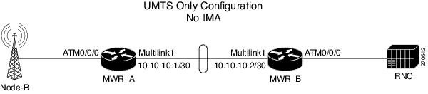
The traditional UMTS configuration is similar to the GSM configuration except only UMTS traffic traverses the topology. Unlike GSM traffic, UMTS traffic arrives at the RAN-O device via ATM PVCs. The UMTS traffic is then routed over the traditional MLPPP backhaul connection. At the RNC side, the RAN-O to RNC connectivity is exactly like the Node-B to RAN-O interface connections. Aside from the necessity of ATM connectivity, the physical connectivity for UMTS is exactly like the GSM topology (see Figure B-9).
Figure B-9 UMTS Only Configuration without IMA
MWR_A
!card type E1 0 0card type E1 0 1!!redundancymode y-cablestandalone!network-clock-participate wic 0network-clock-participate wic 1network-clock-participate aim 1network-clock-select 1 E1 0/0/1!ipran-mib snmp-access inBandipran-mib location cellSite!!controller E1 0/0/0mode atm aim 1clock source internal!controller E1 0/0/1channel-group 0 timeslots 1-31!!class-map match-any llq-classmatch ip dscp ef!!policy-map llq-policyclass llq-classpriority percent 99class class-defaultbandwidth remaining percent 1queue-limit 45!interface Multilink1ip address 10.10.10.1 255.255.255.252load-interval 30no keepaliveno cdp enableppp pfc local requestppp pfc remote applyppp acfc local requestppp acfc remote applyppp multilinkppp multilink interleaveppp multilink group 1ppp multilink fragment delay 0 1ppp multilink multiclassmax-reserved-bandwidth 100service-policy output llq-policyhold-queue 50 outip rtp header-compression ietf-format!!interface ATM0/0/0no ip addressscrambling-payloadno atm ilmi-keepaliveatm umts-iubumts-iub set dscp efumts-iub local 10.10.10.1 6000umts-iub remote 10.10.10.2 6000pvc 1/1 qsaal!pvc 1/2 qsaal!pvc 1/100encapsulation aal0!!!interface Serial0/0/1:0no ip addressencapsulation pppkeepalive 1ppp multilink group 1max-reserved-bandwidth 100!!logging history size 500logging history debugginglogging trap warningssnmp-server community public ROsnmp-server queue-length 100snmp-server enable traps snmp linkdown linkup coldstart warmstartsnmp-server enable traps ipransnmp-server enable traps syslogsnmp-server trap link ietfsnmp-server ifIndex persistno snmp-server sparse-tablesnmp-server host 64.50.100.254 version 2c V2Cdisable-eadiMWR_B
!card type E1 0 0card type E1 0 1!!redundancymode y-cablestandalone!network-clock-participate wic 0network-clock-participate wic 1network-clock-participate aim 1network-clock-select 1 E1 0/0/0!ipran-mib snmp-access outOfBandipran-mib location aggSite!!controller E1 0/0/0mode atm aim 1!controller E1 0/0/1clock source internalchannel-group 0 timeslots 1-31!class-map match-any llq-classmatch ip dscp ef!!policy-map llq-policyclass llq-classpriority percent 99class class-defaultbandwidth remaining percent 1queue-limit 45!interface Multilink1ip address 10.10.10.2 255.255.255.252load-interval 30no keepaliveno cdp enableppp pfc local requestppp pfc remote applyppp acfc local requestppp acfc remote applyppp multilinkppp multilink interleaveppp multilink group 1ppp multilink fragment delay 0 1ppp multilink multiclassmax-reserved-bandwidth 100service-policy output llq-policyhold-queue 50 outip rtp header-compression ietf-format!!interface ATM0/0/0no ip addressscrambling-payloadno atm ilmi-keepaliveatm umts-iubumts-iub set dscp efumts-iub local 10.10.10.2 6000umts-iub remote 10.10.10.1 6000pvc 1/1 qsaal!pvc 1/2 qsaal!pvc 1/100encapsulation aal0!!interface Serial0/0/1:0no ip addressencapsulation pppkeepalive 1ppp multilink group 1max-reserved-bandwidth 100!logging history size 500logging history debugginglogging trap warningssnmp-server community public ROsnmp-server queue-length 100snmp-server enable traps snmp linkdown linkup coldstart warmstartsnmp-server enable traps ipransnmp-server enable traps syslogsnmp-server trap link ietfsnmp-server ifIndex persistno snmp-server sparse-tablesnmp-server host 64.50.100.254 version 2c V2Cdisable-eadiCombined GSM and UMTS Configuration
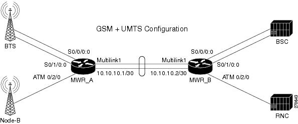
The combined GSM and UMTS configuration allows both the GSM and UMTS technologies to become aggregated over the traditional multilink backhaul connection (see Figure B-10).
Figure B-10 Combined GSM and UMTS Configuration
MWR_A
!card type E1 0 0card type E1 0 1card type E1 0 2!!redundancymode y-cablestandalone!network-clock-participate wic 0network-clock-participate wic 1network-clock-participate wic 2network-clock-participate aim 1network-clock-select 1 E1 0/0/1network-clock-select 1 E1 0/1/1!ipran-mib snmp-access inBandipran-mib location cellSite!!controller E1 0/0/0framing NO-CRC4clock source internalchannel-group 0 timeslots 1-31!controller E1 0/0/1channel-group 0 timeslots 1-31!controller E1 0/1/0framing NO-CRC4clock source internalchannel-group 0 timeslots 1-31!controller E1 0/1/1channel-group 0 timeslots 1-31!controller E1 0/2/0clock source internalmode atm aim 1!class-map match-any llq-classmatch ip dscp ef!!policy-map llq-policyclass llq-classpriority percent 99class class-defaultbandwidth remaining percent 1queue-limit 45!interface Multilink1ip address 10.10.10.1 255.255.255.252load-interval 30no keepaliveno cdp enableppp pfc local requestppp pfc remote applyppp acfc local requestppp acfc remote applyppp multilinkppp multilink interleaveppp multilink group 1ppp multilink fragment delay 0 1ppp multilink multiclassmax-reserved-bandwidth 100service-policy output llq-policyhold-queue 50 outip rtp header-compression ietf-format!interface Serial0/0/0:0no ip addressencapsulation gsm-abisgsm-abis local 10.10.10.1 4444gsm-abis remote 10.10.10.2 4444gsm-abis set dscp efno keepalive!interface Serial0/0/1:0no ip addressencapsulation pppkeepalive 1ppp multilink group 1max-reserved-bandwidth 100!interface Serial0/1/0:0no ip addressencapsulation gsm-abisgsm-abis local 10.10.10.1 4446gsm-abis remote 10.10.10.2 4446gsm-abis set dscp efno keepalive!interface Serial0/1/1:0no ip addressencapsulation pppkeepalive 1ppp multilink group 1max-reserved-bandwidth 100!interface ATM0/2/0no ip addressscrambling-payloadno atm ilmi-keepaliveatm umts-iubumts-iub set dscp efumts-iub local 10.10.10.1 6000umts-iub remote 10.10.10.2 6000pvc 1/1 qsaal!pvc 1/2 qsaal!pvc 1/100encapsulation aal0!!logging history size 500logging history debugginglogging trap warningssnmp-server community public ROsnmp-server queue-length 100snmp-server enable traps snmp linkdown linkup coldstart warmstartsnmp-server enable traps ipransnmp-server enable traps syslogsnmp-server trap link ietfsnmp-server ifIndex persistno snmp-server sparse-tablesnmp-server host 64.50.100.254 version 2c V2Cdisable-eadiMWR_B
!card type E1 0 0card type E1 0 1card type E1 0 2!!redundancymode y-cablestandalone!network-clock-participate wic 0network-clock-participate wic 1network-clock-participate wic 2network-clock-participate aim 1network-clock-select 1 E1 0/0/0network-clock-select 2 E1 0/1/0network-clock-select 3 E1 0/2/0!ipran-mib snmp-access outOfBandipran-mib location aggSite!!controller E1 0/0/0framing NO-CRC4channel-group 0 timeslots 1-31!controller E1 0/0/1clock source internalchannel-group 0 timeslots 1-31!controller E1 0/1/0framing NO-CRC4channel-group 0 timeslots 1-31!controller E1 0/1/1clock source internalchannel-group 0 timeslots 1-31!!controller E1 0/2/0mode atm aim 1!class-map match-any llq-classmatch ip dscp ef!!policy-map llq-policyclass llq-classpriority percent 99class class-defaultbandwidth remaining percent 1queue-limit 45!interface Multilink1ip address 10.10.10.2 255.255.255.252load-interval 30no keepaliveno cdp enableppp pfc local requestppp pfc remote applyppp acfc local requestppp acfc remote applyppp multilinkppp multilink interleaveppp multilink group 1ppp multilink fragment delay 0 1ppp multilink multiclassmax-reserved-bandwidth 100service-policy output llq-policyhold-queue 50 outip rtp header-compression ietf-format!!interface Serial0/0/0:0no ip addressencapsulation gsm-abisgsm-abis local 10.10.10.2 4444gsm-abis remote 10.10.10.1 4444gsm-abis set dscp efno keepalive!interface Serial0/0/1:0no ip addressencapsulation pppkeepalive 1ppp multilink group 1max-reserved-bandwidth 100!interface Serial0/1/0:0no ip addressencapsulation gsm-abisgsm-abis local 10.10.10.2 4446gsm-abis remote 10.10.10.1 4446gsm-abis set dscp efno keepalive!interface Serial0/1/1:0no ip addressencapsulation pppkeepalive 1ppp multilink group 1max-reserved-bandwidth 100!interface ATM0/2/0no ip addressscrambling-payloadno atm ilmi-keepaliveatm umts-iubumts-iub set dscp efumts-iub local 10.10.10.2 6000umts-iub remote 10.10.10.1 6000pvc 1/1 qsaal!pvc 1/2 qsaal!pvc 1/100encapsulation aal0!!logging history size 500logging history debugginglogging trap warningssnmp-server community public ROsnmp-server queue-length 100snmp-server enable traps snmp linkdown linkup coldstart warmstartsnmp-server enable traps ipransnmp-server enable traps syslogsnmp-server trap link ietfsnmp-server ifIndex persistno snmp-server sparse-tablesnmp-server host 64.50.100.254 version 2c V2Cdisable-eadiGSM and UMTS with IMA Configuration
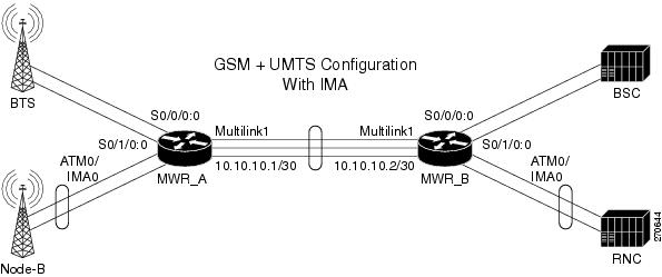
The combined GSM and UMTS with Inverse Multiplexing over ATM (IMA) configuration allows both the GSM and UMTS technologies to become aggregated over the traditional multilink backhaul connection (see Figure B-11).
Figure B-11 GSM and UMTS with IMA Configuration
MWR_A
!card type E1 0 0card type E1 0 1card type E1 0 2card type E1 1 0!!redundancymode y-cablestandalone!network-clock-participate wic 0network-clock-participate wic 1network-clock-participate wic 2network-clock-participate slot 1network-clock-participate aim 1network-clock-select 1 E1 0/0/1network-clock-select 2 E1 0/1/1network-clock-select 3 E1 0/2/1!ipran-mib snmp-access inBandipran-mib location cellSite!!controller E1 0/0/0framing NO-CRC4clock source internalchannel-group 0 timeslots 1-31!controller E1 0/0/1channel-group 0 timeslots 1-31!controller E1 0/1/0framing NO-CRC4clock source internalchannel-group 0 timeslots 1-31!controller E1 0/1/1channel-group 0 timeslots 1-31!controller E1 0/2/0clock source internalmode atm aim 1!controller E1 0/2/1channel-group 0 timeslots 1-31!controller E1 1/0/0clock source internalmode atm aim 1!class-map match-any llq-classmatch ip dscp ef!!policy-map llq-policyclass llq-classpriority percent 99class class-defaultbandwidth remaining percent 1queue-limit 45!interface Multilink1ip address 10.10.10.1 255.255.255.252load-interval 30no keepaliveno cdp enableppp pfc local requestppp pfc remote applyppp acfc local requestppp acfc remote applyppp multilinkppp multilink interleaveppp multilink group 1ppp multilink fragment delay 0 1ppp multilink multiclassmax-reserved-bandwidth 100service-policy output llq-policyhold-queue 50 outip rtp header-compression ietf-format!interface Serial0/0/0:0no ip addressencapsulation gsm-abisgsm-abis local 10.10.10.1 4444gsm-abis remote 10.10.10.2 4444gsm-abis set dscp efno keepalive!interface Serial0/0/1:0no ip addressencapsulation pppkeepalive 1ppp multilink group 1max-reserved-bandwidth 100!interface Serial0/1/0:0no ip addressencapsulation gsm-abisgsm-abis local 10.10.10.1 4446gsm-abis remote 10.10.10.2 4446gsm-abis set dscp efno keepalive!interface Serial0/1/1:0no ip addressencapsulation pppkeepalive 1ppp multilink group 1max-reserved-bandwidth 100!interface ATM0/2/0no ip addressscrambling-payloadno atm ilmi-keepaliveima-group 0!interface Serial0/2/1:0no ip addressencapsulation pppkeepalive 1ppp multilink group 1max-reserved-bandwidth 100!interface ATM1/0/0no ip addressscrambling-payloadno atm ilmi-keepaliveima-group 0!interface ATM0/IMA0no ip addressatm bandwidth dynamicatm umts-iubumts-iub set dscp efumts-iub local 10.10.10.1 6000umts-iub remote 10.10.10.2 6000no atm ilmi-keepalivepvc 2/1encapsulation aal0!pvc 2/2 qsaal!!!logging history size 500logging history debugginglogging trap warningssnmp-server community public ROsnmp-server queue-length 100snmp-server enable traps snmp linkdown linkup coldstart warmstartsnmp-server enable traps ipransnmp-server enable traps syslogsnmp-server trap link ietfsnmp-server ifIndex persistno snmp-server sparse-tablesnmp-server host 64.50.100.254 version 2c V2Cdisable-eadiMWR_B
!card type E1 0 0card type E1 0 1card type E1 0 2card type E1 1 0!!redundancymode y-cablestandalone!network-clock-participate wic 0network-clock-participate wic 1network-clock-participate wic 2network-clock-participate slot 1network-clock-participate aim 1network-clock-select 1 E1 0/0/0network-clock-select 2 E1 0/1/0network-clock-select 3 E1 0/2/0!ipran-mib snmp-access outOfBandipran-mib location aggSite!!controller E1 0/0/0framing NO-CRC4channel-group 0 timeslots 1-31!controller E1 0/0/1clock source internalchannel-group 0 timeslots 1-31!controller E1 0/1/0framing NO-CRC4channel-group 0 timeslots 1-31!controller E1 0/1/1clock source internalchannel-group 0 timeslots 1-31!!controller E1 0/2/0mode atm aim 1!controller E1 0/2/1clock source internalchannel-group 0 timeslots 1-31!controller E1 1/0/0mode atm aim 1!class-map match-any llq-classmatch ip dscp ef!!policy-map llq-policyclass llq-classpriority percent 99class class-defaultbandwidth remaining percent 1queue-limit 45!interface Multilink1ip address 10.10.10.2 255.255.255.252load-interval 30no keepaliveno cdp enableppp pfc local requestppp pfc remote applyppp acfc local requestppp acfc remote applyppp multilinkppp multilink interleaveppp multilink group 1ppp multilink fragment delay 0 1ppp multilink multiclassmax-reserved-bandwidth 100service-policy output llq-policyhold-queue 50 outip rtp header-compression ietf-format!interface Serial0/0/0:0no ip addressencapsulation gsm-abisgsm-abis local 10.10.10.2 4444gsm-abis remote 10.10.10.1 4444gsm-abis set dscp efno keepalive!interface Serial0/0/1:0no ip addressencapsulation pppkeepalive 1ppp multilink group 1max-reserved-bandwidth 100!interface Serial0/1/0:0no ip addressencapsulation gsm-abisgsm-abis local 10.10.10.2 4446gsm-abis remote 10.10.10.1 4446gsm-abis set dscp efno keepalive!interface Serial0/1/1:0no ip addressencapsulation pppkeepalive 1ppp multilink group 1max-reserved-bandwidth 100!interface ATM0/2/0no ip addressscrambling-payloadno atm ilmi-keepaliveima-group 0!interface Serial0/2/1:0no ip addressencapsulation pppkeepalive 1ppp multilink group 1max-reserved-bandwidth 100!interface ATM1/0/0no ip addressscrambling-payloadno atm ilmi-keepaliveima-group 0!interface ATM0/IMA0no ip addressatm bandwidth dynamicatm umts-iubumts-iub set dscp efumts-iub local 10.10.10.2 6000umts-iub remote 10.10.10.1 6000no atm ilmi-keepalivepvc 2/1encapsulation aal0!pvc 2/2 qsaal!!!logging history size 500logging history debugginglogging trap warningssnmp-server community public ROsnmp-server queue-length 100snmp-server enable traps snmp linkdown linkup coldstart warmstartsnmp-server enable traps ipransnmp-server enable traps syslogsnmp-server trap link ietfsnmp-server ifIndex persistno snmp-server sparse-tablesnmp-server host 64.50.100.254 version 2c V2Cdisable-eadiGSM and UMTS with IMA and PVC Routing (HSDPA Offload) Configuration
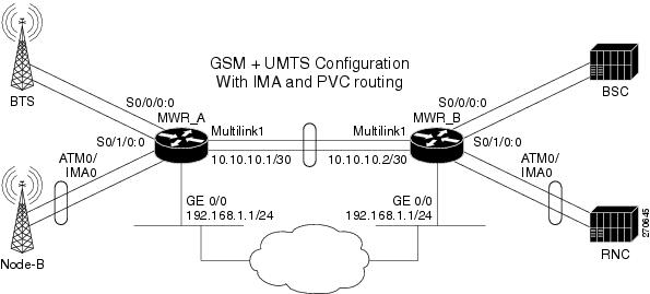
The combined GSM and UMTS with IMA and PVC Routing configuration allows PVC Routing to be off-loaded to an alternate backhaul (see Figure B-12).
Figure B-12 GSM and UMTS with IMA and PVC Routing (HSDPA Offload) Configuration
MWR_A
!card type E1 0 0card type E1 0 1card type E1 0 2!!redundancymode y-cablestandalone!network-clock-participate wic 0network-clock-participate wic 1network-clock-participate wic 2network-clock-participate aim 1network-clock-select 1 E1 0/0/1network-clock-select 2 E1 0/1/1!ipran-mib snmp-access inBandipran-mib location cellSite!!controller E1 0/0/0framing NO-CRC4clock source internalchannel-group 0 timeslots 1-31!controller E1 0/0/1channel-group 0 timeslots 1-31!controller E1 0/1/0framing NO-CRC4clock source internalchannel-group 0 timeslots 1-31!controller E1 0/1/1channel-group 0 timeslots 1-31!!controller E1 0/2/0clock source internalmode atm aim 1!controller E1 0/2/1clock source internalmode atm aim 1!class-map match-any llq-classmatch ip dscp ef!!policy-map llq-policyclass llq-classpriority percent 99class class-defaultbandwidth remaining percent 1queue-limit 45!interface Multilink1ip address 10.10.10.1 255.255.255.252load-interval 30no keepaliveno cdp enableppp pfc local requestppp pfc remote applyppp acfc local requestppp acfc remote applyppp multilinkppp multilink interleaveppp multilink group 1ppp multilink fragment delay 0 1ppp multilink multiclassmax-reserved-bandwidth 100service-policy output llq-policyhold-queue 50 outip rtp header-compression ietf-format!interface GigabitEthernet0/0ip address 192.168.1.1 255.255.255.0duplex autospeed auto!interface Serial0/0/0:0no ip addressencapsulation gsm-abisgsm-abis local 10.10.10.1 4444gsm-abis remote 10.10.10.2 4444gsm-abis set dscp efno keepalive!interface Serial0/0/1:0no ip addressencapsulation pppkeepalive 1ppp multilink group 1max-reserved-bandwidth 100!interface Serial0/1/0:0no ip addressencapsulation gsm-abisgsm-abis local 10.10.10.1 4446gsm-abis remote 10.10.10.2 4446gsm-abis set dscp efno keepalive!interface Serial0/1/1:0no ip addressencapsulation pppkeepalive 1ppp multilink group 1max-reserved-bandwidth 100!interface ATM0/2/0no ip addressscrambling-payloadno atm ilmi-keepaliveima-group 0!interface ATM0/2/1no ip addressscrambling-payloadno atm ilmi-keepaliveima-group 0!interface ATM0/IMA0no ip addressatm bandwidth dynamicatm umts-iubumts-iub set dscp efumts-iub set peering dscp efumts-iub local 10.10.10.1 6000umts-iub remote 10.10.10.2 6000no atm ilmi-keepalivepvc 2/1encapsulation aal0!pvc 2/2 qsaal!!interface ATM0/IMA0.1 multipointatm umts-iubumts-iub set dscp efumts-iub set peering dscp efumts-iub local 192.168.1.1umts-iub remote 192.168.1.2pvc 2/3encapsulation aal0!!logging history size 500logging history debugginglogging trap warningssnmp-server community public ROsnmp-server queue-length 100snmp-server enable traps snmp linkdown linkup coldstart warmstartsnmp-server enable traps ipransnmp-server enable traps syslogsnmp-server trap link ietfsnmp-server ifIndex persistno snmp-server sparse-tablesnmp-server host 64.50.100.254 version 2c V2Cdisable-eadiMWR_B
!card type E1 0 0card type E1 0 1card type E1 0 2!!redundancymode y-cablestandalone!network-clock-participate wic 0network-clock-participate wic 1network-clock-participate wic 2network-clock-participate aim 1network-clock-select 1 E1 0/0/0network-clock-select 2 E1 0/1/0network-clock-select 3 E1 0/2/0network-clock-select 4 E1 0/2/1!ipran-mib snmp-access outOfBandipran-mib location aggSite!!controller E1 0/0/0framing NO-CRC4channel-group 0 timeslots 1-31!controller E1 0/0/1clock source internalchannel-group 0 timeslots 1-31!controller E1 0/1/0framing NO-CRC4channel-group 0 timeslots 1-31!controller E1 0/1/1clock source internalchannel-group 0 timeslots 1-31!controller E1 0/2/0mode atm aim 1!controller E1 0/2/1mode atm aim 1!!class-map match-any llq-classmatch ip dscp ef!!policy-map llq-policyclass llq-classpriority percent 99class class-defaultbandwidth remaining percent 1queue-limit 45!interface Multilink1ip address 10.10.10.2 255.255.255.252load-interval 30no keepaliveno cdp enableppp pfc local requestppp pfc remote applyppp acfc local requestppp acfc remote applyppp multilinkppp multilink interleaveppp multilink group 1ppp multilink fragment delay 0 1ppp multilink multiclassmax-reserved-bandwidth 100service-policy output llq-policyhold-queue 50 outip rtp header-compression ietf-format!interface GigabitEthernet0/0ip address 192.168.1.2 255.255.255.0duplex autospeed auto!interface Serial0/0/0:0no ip addressencapsulation gsm-abisgsm-abis local 10.10.10.2 4444gsm-abis remote 10.10.10.1 4444gsm-abis set dscp efno keepalive!interface Serial0/0/1:0no ip addressencapsulation pppkeepalive 1ppp multilink group 1max-reserved-bandwidth 100!interface Serial0/1/0:0no ip addressencapsulation gsm-abisgsm-abis local 10.10.10.2 4446gsm-abis remote 10.10.10.1 4446gsm-abis set dscp efno keepalive!interface Serial0/1/1:0no ip addressencapsulation pppkeepalive 1ppp multilink group 1max-reserved-bandwidth 100!interface ATM0/2/0no ip addressscrambling-payloadno atm ilmi-keepaliveima-group 0!interface ATM0/2/1no ip addressscrambling-payloadno atm ilmi-keepaliveima-group 0!interface ATM0/IMA0no ip addressatm bandwidth dynamicatm umts-iubumts-iub set dscp efumts-iub set peering dscp efumts-iub local 10.10.10.2 6000umts-iub remote 10.10.10.1 6000no atm ilmi-keepalivepvc 2/1encapsulation aal0!pvc 2/2 qsaal!!interface ATM0/IMA0.1 multipointatm umts-iubumts-iub set dscp efumts-iub peering dscp efumts-iub local 192.168.1.2umts-iub remote 192.168.1.1pvc 2/3encapsulation aal0!!logging history size 500logging history debugginglogging trap warningssnmp-server community public ROsnmp-server queue-length 100snmp-server enable traps snmp linkdown linkup coldstart warmstartsnmp-server enable traps ipransnmp-server enable traps syslogsnmp-server trap link ietfsnmp-server ifIndex persistno snmp-server sparse-tablesnmp-server host 64.50.100.254 version 2c V2Cdisable-eadiGSM Only Configuration via Satellite
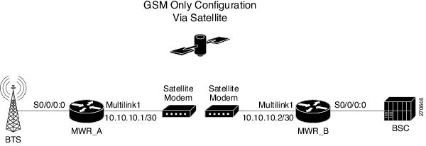
The GSM only via satellite configuration allows for point-to-point network optimization (see Figure B-13).
Figure B-13 GSM Only Configuration via Satellite
MWR_A
!card type E1 0 0!!redundancymode y-cablestandalone!network-clock-participate wic 0network-clock-participate aim 1network-clock-select 1 E1 0/0/1!ipran-mib snmp-access inBandipran-mib location cellSite!!controller E1 0/0/0framing NO-CRC4clock source internalchannel-group 0 timeslots 1-20!controller E1 0/0/1channel-group 0 timeslots 1-20!!class-map match-any llq-classmatch ip dscp ef!!policy-map llq-policyclass llq-classpriority percent 99class class-defaultbandwidth remaining percent 1queue-limit 45!interface Multilink1ip address 10.10.10.1 255.255.255.252load-interval 30no keepaliveno cdp enableppp pfc local requestppp pfc remote applyppp acfc local requestppp acfc remote applyppp multilinkppp multilink interleaveppp multilink group 1ppp multilink fragment delay 0 1ppp multilink multiclassmax-reserved-bandwidth 100service-policy output llq-policyhold-queue 50 outip rtp header-compression ietf-format!!interface Serial0/0/0:0no ip addressencapsulation gsm-abisgsm-abis local 10.10.10.1 4444gsm-abis remote 10.10.10.2 4444gsm-abis set dscp efno keepalive!interface Serial0/0/1:0no ip addressencapsulation pppkeepalive 1ppp multilink group 1max-reserved-bandwidth 100!logging history size 500logging history debugginglogging trap warningssnmp-server community public ROsnmp-server queue-length 100snmp-server enable traps snmp linkdown linkup coldstart warmstartsnmp-server enable traps ipransnmp-server enable traps syslogsnmp-server trap link ietfsnmp-server ifIndex persistno snmp-server sparse-tablesnmp-server host 64.50.100.254 version 2c V2Cdisable-eadiMWR_B
!card type E1 0 0!!redundancymode y-cablestandalone!network-clock-participate wic 0network-clock-participate aim 1network-clock-select 1 E1 0/0/0!ipran-mib snmp-access outOfBandipran-mib location aggSite!!controller E1 0/0/0framing NO-CRC4channel-group 0 timeslots 1-20!controller E1 0/0/1clock source internalchannel-group 0 timeslots 1-20!!class-map match-any llq-classmatch ip dscp ef!!policy-map llq-policyclass llq-classpriority percent 99class class-defaultbandwidth remaining percent 1queue-limit 45!interface Multilink1ip address 10.10.10.2 255.255.255.252load-interval 30no keepaliveno cdp enableppp pfc local requestppp pfc remote applyppp acfc local requestppp acfc remote applyppp multilinkppp multilink interleaveppp multilink group 1ppp multilink fragment delay 0 1ppp multilink multiclassmax-reserved-bandwidth 100service-policy output llq-policyhold-queue 50 outip rtp header-compression ietf-format!!interface Serial0/0/0:0no ip addressencapsulation gsm-abisgsm-abis local 10.10.10.2 4444gsm-abis remote 10.10.10.1 4444gsm-abis set dscp efno keepalive!interface Serial0/0/1:0no ip addressencapsulation pppkeepalive 1ppp multilink group 1max-reserved-bandwidth 100!logging history size 500logging history debugginglogging trap warningssnmp-server community public ROsnmp-server queue-length 100snmp-server enable traps snmp linkdown linkup coldstart warmstartsnmp-server enable traps ipransnmp-server enable traps syslogsnmp-server trap link ietfsnmp-server ifIndex persistno snmp-server sparse-tablesnmp-server host 64.50.100.254 version 2c V2Cdisable-eadiGSM Congestion Management
The GSM congestion management configuration.
BTS side:
interface Serial0/0/0:0no ip addressencapsulation gsm-abisgsm-abis local 10.10.10.1 4444gsm-abis remote 10.10.10.2 4444gsm-abis congestion enablegsm-abis congestion critical 1-10gsm-abis congestion critical 31gsm-abis set dscp efno keepaliveBSC side:
interface Serial0/0/0:0no ip addressencapsulation gsm-abisgsm-abis local 10.10.10.2 4444gsm-abis remote 10.10.10.1 4444gsm-abis congestion enablegsm-abis congestion critical 1-10gsm-abis congestion critical 31gsm-abis set dscp efno keepaliveUMTS Congestion Management
The UMTS congestion management configuration.
Node-B side:
interface ATM0/2/0no ip addressscrambling-payloadno atm ilmi-keepaliveatm umts-iubumts-iub set dscp efumts-iub congestion-controlumts-iub local 10.10.10.1 6000umts-iub remote 10.10.10.2 6000pvc 1/1 qsaalumts-iub congestion priority protected!pvc 1/2 qsaalumts-iub congestion priority 2!pvc 1/100encapsulation aal0umts-iub congestion priority 5!RNC side:
interface ATM0/2/0no ip addressscrambling-payloadno atm ilmi-keepaliveatm umts-iubumts-iub set dscp efumts-iub congestion-controlumts-iub local 10.10.10.2 6000umts-iub remote 10.10.10.1 6000pvc 1/1 qsaalumts-iub congestion priority protected!pvc 1/2 qsaalumts-iub congestion priority 2!pvc 1/100encapsulation aal0umts-iub congestion priority 5!