Table Of Contents
System Testing
Revised: December 21, 2009This chapter describes the tests performed on the Services Ready Large Branch Network.
Contents
Test Result Summary
Table 1 lists the test cases and their results.
Test Setups
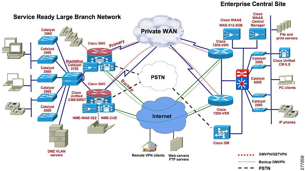
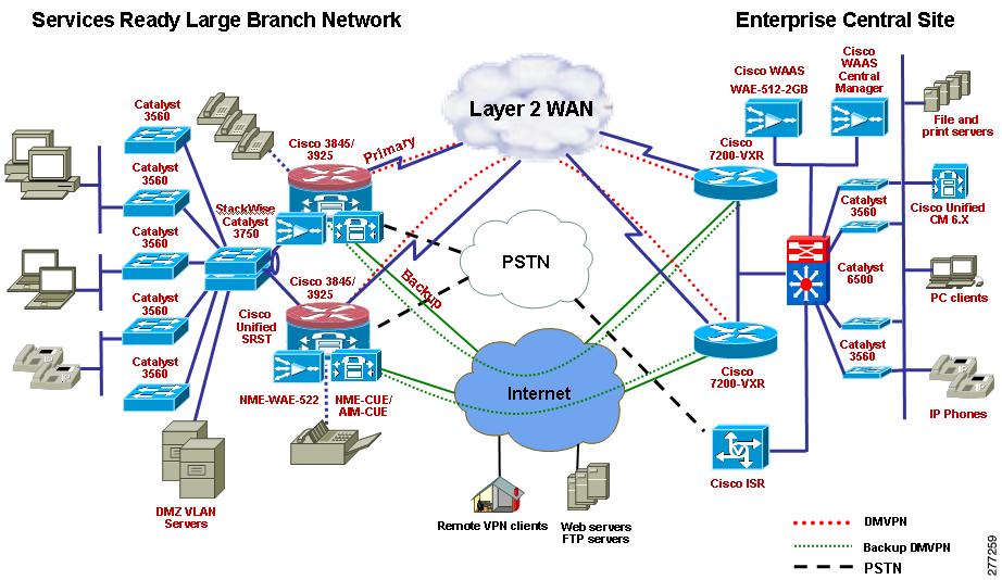
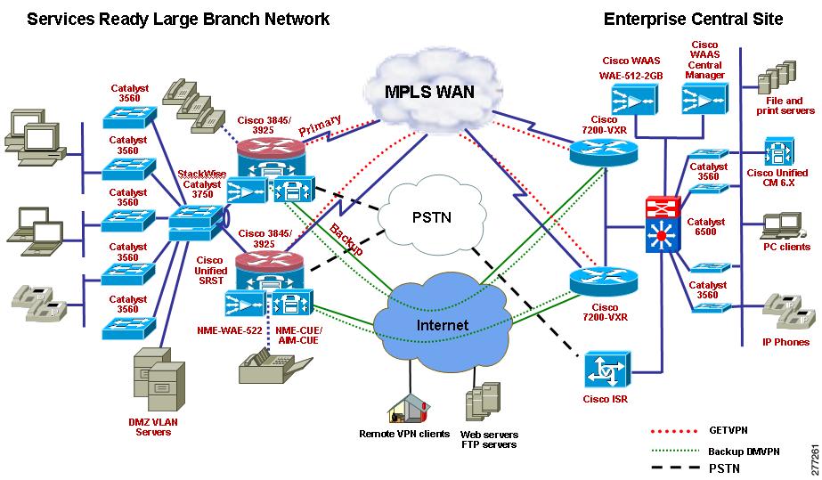
The test cases described in this section use the test setups shown in Figure 1 through Figure 4, in addition to test setups shown in the other figures referenced in the specific test case.
Figure 1 Private WAN, Cisco Unified CME Mode
Figure 2 Private WAN, Cisco Unified SRST Mode
Figure 3 MPLS WAN, Cisco Unified CME Mode
Figure 4 MPLS WAN, Cisco Unified SRST Mode
Traffic Profile
The following traffic profile was used to represent typical traffic in a large enterprise branch network.
HTTP Traffic—75 percent
•
16 KB object size representing large HTML files containing images (10 URLs)
•
FTP Traffic—10 percent
•
SMTP Traffic—10 percent
•
DNZ Traffic—5 percent
•
Test Cases
This section contains the following test cases:
•
•
WAN Connectivity Test Cases
DS3 Primary WAN Connections for Cisco 3900 Series Large Branch
Gigabit Ethernet Primary WAN Connection for Cisco 3900 Series Large Branch
MLPPP Primary WAN Connection for Cisco 3900 Series Large Branch
MLFR Primary WAN Connection for Cisco 3900 Series Large Branch
SHDSL IMA Secondary WAN Connection for Cisco 3900 Series Large Branch
Interface Removal and Addition to SHDSL IMA Interface
Network Services Test Cases
Layer 2 Access Layer Switch
Set up Catalyst 3560 switches as access layer switches
Figure 1, Private WAN, Cisco Unified CME Mode, or
Figure 2, Private WAN, Cisco Unified SRST Mode, or
Figure 3, MPLS WAN, Cisco Unified CME Mode, or
1.
2.
3.
4.
Layer 2 voice, data, management, and DMZ VLANs should come up. During master distribution switch failure, Layer 2 convergence should happen within a second.
Passed
L2 Security-802.1x Authentication on the Access Layer Switch
Set up to verify 802.1x authentication on one of the access layer switches.
Figure 1, Private WAN, Cisco Unified CME Mode, or
Figure 2, Private WAN, Cisco Unified SRST Mode, or
Figure 3, MPLS WAN, Cisco Unified CME Mode, or
1.
2.
3.
4.
5.
6.
7.
8.
9.
The IP Phones and PCs should obtain IP addresses from the DHCP server on the router and not from the Windows DHCP server, because the Widows server is connected to a non-trusted port.
DAI should build dynamic entries (ACLs) with IP addresses (obtained through DHCP) and corresponding MAC addresses for the phones and PCs.
If a laptop with a statically configured IP address (in the y VLAN) is connected to a switch port associated to the y VLAN, the DAI should prevent the laptop from obtaining network connectivity; that is, it builds a deny ACL for this laptop.
Passed
L2 Security-DHCP Snooping and Dynamic ARP Inspection on Access Layer Switch
Set up to verify DHCP snooping and Dynamic ARP inspection on one of the access switches
Figure 1, Private WAN, Cisco Unified CME Mode, or
Figure 2, Private WAN, Cisco Unified SRST Mode, or
Figure 3, MPLS WAN, Cisco Unified CME Mode, or
1.
2.
3.
4.
5.
6.
7.
8.
9.
10.
11.
12.
The traffic should be distributed 2:1 between the primary and secondary router.
The standby router should take over control after the primary router is power cycled.
When power returns to the primary router, it should take over control from the standby router after waiting for the preemption time to expire.
Passed
L2 Security-Port Security on Access Layer Switch
Set up to verify port security on one of the access layer switches
Figure 1, Private WAN, Cisco Unified CME Mode, or
Figure 2, Private WAN, Cisco Unified SRST Mode, or
Figure 3, MPLS WAN, Cisco Unified CME Mode, or
1.
2.
3.
4.
When the laptop is connected to the switch port, it should get an IP address through DHCP. The switch should populate the laptop's MAC address and port information into a port security table.
When another laptop with a different MAC address is connected to the same port, a port security violation error should be displayed on the console of the switch, and the new laptop should not be provided with an IP address.
Passed
L2 Security-IP Source Guard on the Access Layer Switch
Set up to verify IP source guard on one of the access layer switches
Figure 1, Private WAN, Cisco Unified CME Mode, or
Figure 2, Private WAN, Cisco Unified SRST Mode, or
Figure 3, MPLS WAN, Cisco Unified CME Mode, or
1.
2.
3.
4.
The traffic from the traffic generator should be successfully allowed from the switch port and should reach the traffic generator at HQ.
The IP source guard feature validates the source MAC address of the host that is connected to the switch port on which the IP source guard is enabled. It associates the host MAC address to the IP address obtained through DHCP.
Once the traffic generator MAC address is changed, traffic should be dropped and not be allowed to pass from the switch port.
Passed
L2 Security-BPDU Guard on the Access Layer Switch
Set up to verify BPDU guard on one of the access layer switches
Figure 1, Private WAN, Cisco Unified CME Mode, or
Figure 2, Private WAN, Cisco Unified SRST Mode, or
Figure 3, MPLS WAN, Cisco Unified CME Mode, or
1.
2.
The phones and PC ports should be operational and able to send traffic normally after enabling BPDU guard.
The port shut down after connecting the switch.
Passed
Layer 3 Distribution Switches in a Stack
Connect Catalyst 3750 distribution layer switches (at least two) using Cisco StackWise technology, and enable Layer 3 routing.
Figure 1, Private WAN, Cisco Unified CME Mode, or
Figure 2, Private WAN, Cisco Unified SRST Mode, or
Figure 3, MPLS WAN, Cisco Unified CME Mode, or
1.
2.
3.
4.
5.
When the Catalyst 3750 switches are stacked together, they should appear as one switch to any outside entity, such as a branch router. One of the switches in the stack is the stack master, and the rest of them are slaves. The stack master should hold the VLAN database and configuration; the slaves should retain a copy. The stack master should also have console access to the stacked switches.
Passed
QoS on the LAN
Enable conditionally trusted IP Phone and PC and scavenger-class traffic (Advanced) Model Configuration on the Catalyst 3750 and Catalyst 3560 switches
Figure 1, Private WAN, Cisco Unified CME Mode, or
Figure 2, Private WAN, Cisco Unified SRST Mode, or
Figure 3, MPLS WAN, Cisco Unified CME Mode, or
1.
2.
3.
4.
5.
6.
7.
8.
9.
10.
show mls qos
show mls qos map
show mls qos interface
show mls qos interface policers
show class-map
show policy-map
show policy interface
Voice and data packets should be properly marked by the switches.
Excess traffic should be re-marked to scavenger class and dropped if the scavenger class limit is also exceeded.
Queuing should be engaged only during congestion.
Each traffic type should be properly queued based on the queue assignments.
Passed
WAN Edge QoS-8 Class QoS Model
LLQ for Voice and Interactive Video Traffic
CBWFQ and WRED for Data Traffic
Traffic Shaping on Different WAN Links
Enable traffic shaping on the WAN interface as part of the hierarchical QoS configuration
Figure 1, Private WAN, Cisco Unified CME Mode, or
Figure 2, Private WAN, Cisco Unified SRST Mode, or
Figure 3, MPLS WAN, Cisco Unified CME Mode, or
1.
2.
The egress traffic should be shaped to an average of 95% of the total available bandwidth.
Passed
DSCP/CoS Marking Incoming/Returning Traffic from WAN to LAN
Re-mark ingress traffic to the router coming from the WAN and going to the LAN
Figure 1, Private WAN, Cisco Unified CME Mode, or
Figure 2, Private WAN, Cisco Unified SRST Mode, or
Figure 3, MPLS WAN, Cisco Unified CME Mode, or
1.
2.
The ingress traffic should be properly marked.
Passed
Modification and Deletion of ACLs Defined with Class Map match access-group Command
Modify or delete ACLs defined under class-map configuration mode using match access-group statements
Figure 1, Private WAN, Cisco Unified CME Mode, or
Figure 2, Private WAN, Cisco Unified SRST Mode, or
Figure 3, MPLS WAN, Cisco Unified CME Mode, or
1.
2.
3.
4.
5.
The ACL changes or deletions should not have no adverse impact on the router such as tracebacks, memory leaks, or a crash. The changes should be properly handled and applied to the traffic stream.
Passed
Unconfigure and Reconfigure QoS
Remove QoS configuration, and reapply QoS configuration
Figure 1, Private WAN, Cisco Unified CME Mode, or
Figure 2, Private WAN, Cisco Unified SRST Mode, or
Figure 3, MPLS WAN, Cisco Unified CME Mode, or
1.
2.
There should be no adverse impact on the router such as tracebacks, memory leaks, or a crash.
Passed
Unconfigure QoS, Reload Router, and Reconfigure QoS
Remove QoS configuration, and reapply QoS configuration after router reload
Figure 1, Private WAN, Cisco Unified CME Mode, or
Figure 2, Private WAN, Cisco Unified SRST Mode, or
Figure 3, MPLS WAN, Cisco Unified CME Mode, or
1.
2.
3.
There should be no adverse impact on the router such as tracebacks, memory leaks, or a crash.
Passed
BGP Routing on the Branch
Configure BGP routing to the ISP
Figure 1, Private WAN, Cisco Unified CME Mode, or
Figure 2, Private WAN, Cisco Unified SRST Mode, or
Figure 3, MPLS WAN, Cisco Unified CME Mode, or
1.
2.
3.
4.
5.
6.
BGP should come up between the branch and the ISP. The default route and all other routes injected from the ISP should be visible in the branch router's Routing Information Base (RIB).
Ping should be successful between the branch and headend router.
Passed
OSPF Routing as IGP Between Branch and Headquarters Network
Enable OSPF between the branch router and headend router, and advertise each other's LAN addresses
Figure 1, Private WAN, Cisco Unified CME Mode, or
Figure 2, Private WAN, Cisco Unified SRST Mode, or
Figure 3, MPLS WAN, Cisco Unified CME Mode, or
1.
2.
3.
4.
5.
OSPF adjacency should be established between the branch router and the headend router.
Passed
EIGRP Routing as IGP Between the Branch Router and the Headquarters Router
Enable EIGRP between the branch router and headend router and advertise each other's LAN addresses
Figure 1, Private WAN, Cisco Unified CME Mode, or
Figure 2, Private WAN, Cisco Unified SRST Mode, or
Figure 3, MPLS WAN, Cisco Unified CME Mode, or
1.
2.
3.
4.
5.
EIGRP adjacency should be established between the branch router and the headend router.
Ping should be 100% successful.
Passed
Traffic Measurement Using NetFlow When QoS is Enabled on the Branch Router
Enable NetFlow on the branch router
Figure 1, Private WAN, Cisco Unified CME Mode, or
Figure 2, Private WAN, Cisco Unified SRST Mode, or
Figure 3, MPLS WAN, Cisco Unified CME Mode, or
1.
2.
3.
4.
NetFlow should collect the statistics and export it to the NAM. The collected statistics should be within performance requirements.
Passed
NBAR Classification with QoS
Modify Match Protocol Statements and Bandwidth Percentage
Modify "match protocol" statements and bandwidth percentage in the policy map configuration
Figure 1, Private WAN, Cisco Unified CME Mode, or
Figure 2, Private WAN, Cisco Unified SRST Mode, or
Figure 3, MPLS WAN, Cisco Unified CME Mode, or
Modify the match protocol statements in the NBAR configuration by adding more protocols, changing the existing HTTP URL, and modifying the percentage bandwidth allocated for each traffic class over a live network
Changes should not cause any abnormal behavior in the branch router such as tracebacks, memory leaks, or crashes. Changes should be applied to traffic.
Passed
100 ACLs
Configure about 100 ACLs on the branch router
Figure 1, Private WAN, Cisco Unified CME Mode, or
Figure 2, Private WAN, Cisco Unified SRST Mode, or
Figure 3, MPLS WAN, Cisco Unified CME Mode, or
1.
2.
3.
4.
If a packet does not match any of the statements in the list, the packet should match the permit ip any any statement at the end of the list and be allowed to pass through. If the packet matches any statement in the last, appropriate action such as permit or deny should be taken, depending on what is configured in the ACL statement.
Passed
NTP in the Branch Router
NTP in the branch router
Figure 1, Private WAN, Cisco Unified CME Mode, or
Figure 2, Private WAN, Cisco Unified SRST Mode, or
Figure 3, MPLS WAN, Cisco Unified CME Mode, or
1.
2.
3.
NTP should be sourced from the NTP server after successful authentication.
Passed
Branch Router as a DHCP Server
Branch router as a DHCP server
Figure 1, Private WAN, Cisco Unified CME Mode, or
Figure 2, Private WAN, Cisco Unified SRST Mode, or
Figure 3, MPLS WAN, Cisco Unified CME Mode, or
1.
2.
The DHCP server on the router should be able to provide IP addresses to the clients using DHCP.
Passed
IP SLA VoIP UDP Jitter Codec G.711 u-law (Branch to HQ)
IP SLA VoIP UDP Jitter Codec G.729A u-law (Branch to HQ)
IP SLA ICMP Echo (Branch to HQ)
IPsec Site-to-Site VPN Using DMVPN
Setup an IPsec site-to-site VPN between the branch router and the headend router, using DMVPN.
Figure 1, Private WAN, Cisco Unified CME Mode, or
Figure 2, Private WAN, Cisco Unified SRST Mode, or
Figure 3, MPLS WAN, Cisco Unified CME Mode, or
1.
2.
3.
4.
5.
6.
7.
8.
9.
•
•
•
10.
11.
ISAKMP and IPsec sessions should be established.
The DMVPN tunnel line protocol should come up.
Routing tables at both the branch and headquarters routers should be updated.
Ping should be 100% successful.
Ping traffic should be encrypted.
Passed
IPsec Using GETVPN
Set up an IPsec VPN between the branch router and the headend router, using GETVPN
Figure 3, MPLS WAN, Cisco Unified CME Mode, or
1.
2.
3.
4.
5.
6.
7.
8.
9.
10.
11.
12.
13.
•
•
•
Group members should be registered to the key server.
The key server should successfully push the IPsec SA ACL and rekey the ACL to the group members.
The routing tables at both the branch and head quarters routers should be updated.
Ping should be 100% successful.
Ping traffic should be encrypted.
Passed
GETVPN Unicast Rekeying
GETVPN unicast rekeying
Figure 3, MPLS WAN, Cisco Unified CME Mode, or
1.
2.
3.
4.
5.
6.
7.
8.
9.
10.
Group members should be registered to the key server.
The key server should be able to successfully push the ACL for unicast rekeying to the group members.
After the rekey time out, the key server should send new keys to the group members. For some time, both old keys and new keys should be present in group members. The new key should take over after a certain amount of time, usually within a minute.
Passed
GETVPN Multicast Rekeying
GETVPN multicast rekeying
Figure 3, MPLS WAN, Cisco Unified CME Mode, or
1.
2.
3.
4.
5.
6.
7.
8.
9.
10.
11.
12.
13.
Group members should be registered to the key server.
The key server should be able to successfully push the ACL for multicast rekeying to the group members.
Group members should register to the 239.x.x.x multicast group successfully.
After the rekey timeout, the key server should send new keys to the multicast group. For some time, both old keys and new keys should be present in group members, and the new key should take over after a certain amount of time, usually within a minute.
Passed
IPsec DMVPN with Prefragmentation
IPsec DMVPN with prefragmentation
Figure 1, Private WAN, Cisco Unified CME Mode, or
Figure 2, Private WAN, Cisco Unified SRST Mode, or
Figure 3, MPLS WAN, Cisco Unified CME Mode, or
1.
2.
3.
The IPsec packets that are larger than 1000 bytes should be fragmented.
Passed
IPsec DMVPN and IGP
IPsec DMVPN and IGP
Figure 1, Private WAN, Cisco Unified CME Mode, or
Figure 2, Private WAN, Cisco Unified SRST Mode, or
Figure 3, MPLS WAN, Cisco Unified CME Mode, or
1.
2.
3.
4.
When the IPsec tunnel goes down, the routing tables at both the branch and headquarters are updated. At the branch, the headquarters becomes unreachable, and the routes should be removed from the routing table. Similarly, at the headquarters, the branch becomes unreachable, and routes should be removed from the routing table.
When the tunnel comes back up, the routes at both the branch and headquarters should reappear.
Passed
DMVPN Backup for MPLS Network (Branch to HQ)
DMVPN backup on medium branch using static floating route (Spoke-to-HQ)
Figure 1, Private WAN, Cisco Unified CME Mode, or
Figure 2, Private WAN, Cisco Unified SRST Mode, or
Figure 3, MPLS WAN, Cisco Unified CME Mode, or
1.
2.
3.
4.
5.
Verify that you can reach HQ from the branch when the primary WAN is down.
Passed
DMVPN Backup for MPLS Network (Branch to Branch)
DMVPN backup on medium branch using static floating route (Spoke-to-Spoke)
Figure 1, Private WAN, Cisco Unified CME Mode, or
Figure 2, Private WAN, Cisco Unified SRST Mode, or
Figure 3, MPLS WAN, Cisco Unified CME Mode, or
1.
2.
3.
4.
5.
6.
7.
8.
Verify that you can reach HQ and the small branch from the medium branch when the primary WAN is down.
Passed
DMVPN Backup for MPLS Metwork Using BFD (Branch to HQ)
DMVPN backup with BFD using EIGRP as IGP (Branch to HQ)
Figure 1, Private WAN, Cisco Unified CME Mode, or
Figure 2, Private WAN, Cisco Unified SRST Mode, or
Figure 3, MPLS WAN, Cisco Unified CME Mode, or
1.
2.
3.
4.
5.
6.
7.
8.
9.
10.
11.
Verify that, when the primary WAN fails, EIGRP reconvergence occurs within a second because of BFD.
Verify that all the traffic is routed through the secondary WAN interface.
Verify that voice and HTTP sessions are maintained during reconvergence.
Verify that, when the primary WAN comes up after three minutes, the traffic is routed over the primary WAN interface.
Passed
DMVPN Backup for MPLS Network Using BFD (Branch to Branch)
DMVPN backup with BFD using EIGRP as IGP (Branch to Branch)
Figure 1, Private WAN, Cisco Unified CME Mode, or
Figure 2, Private WAN, Cisco Unified SRST Mode, or
Figure 3, MPLS WAN, Cisco Unified CME Mode, or
1.
2.
3.
4.
5.
6.
7.
8.
9.
10.
11.
Verify that, when the primary WAN fails, EIGRP reconvergence occurs within a second because of BFD.
Verify that all the traffic is routed through the secondary WAN interface.
Verify that voice and HTTP sessions are maintained during reconvergence.
Verify that, when the primary WAN comes up after three minutes, the traffic is routed over the primary WAN interface.
Passed
DMVPN Backup for MPLS Network Using BFD IGP as OSPF (Branch to Branch)
DMVPN backup with BFD using OSPF as IGP (Branch to Branch)
Figure 1, Private WAN, Cisco Unified CME Mode, or
Figure 2, Private WAN, Cisco Unified SRST Mode, or
Figure 3, MPLS WAN, Cisco Unified CME Mode, or
1.
2.
3.
4.
5.
6.
7.
8.
9.
10.
11.
Verify that, when the primary WAN fails, EIGRP reconvergence occurs within a second because of BFD.
Verify that all the traffic is routed through the secondary WAN interface.
Verify that voice and HTTP sessions are maintained during reconvergence.
Verify that, when the primary WAN comes up after three minutes, the traffic is routed over the primary WAN interface.
Passed
DMVPN Backup for MPLS Network Using EBGP (Branch to HQ)
DMVPN backup for MPLS using EBGP
Figure 1, Private WAN, Cisco Unified CME Mode, or
Figure 2, Private WAN, Cisco Unified SRST Mode, or
Figure 3, MPLS WAN, Cisco Unified CME Mode, or
1.
2.
3.
4.
5.
6.
7.
8.
Verify that, when the primary WAN fails, the backup DMVPN comes up.
Verify that voice and HTTP sessions pass through.
Check for appropriate QoS Queues.
When the primary comes up after three minutes, verify that the traffic is routed over the primary WAN interface.
Passed
DMVPN with QoS
DMVPN with QoS
Figure 1, Private WAN, Cisco Unified CME Mode, or
Figure 2, Private WAN, Cisco Unified SRST Mode, or
Figure 3, MPLS WAN, Cisco Unified CME Mode, or
1.
2.
3.
The IPsec packets should get the correct QoS treatment.
Passed
GETVPN with QoS
GETVPN with QoS
Figure 1, Private WAN, Cisco Unified CME Mode, or
Figure 2, Private WAN, Cisco Unified SRST Mode, or
Figure 3, MPLS WAN, Cisco Unified CME Mode, or
1.
2.
3.
The IPsec packets should get the correct QoS treatment.
Passed
DMVPN with QoS and NBAR
DMVPN with QoS and NBAR
Figure 1, Private WAN, Cisco Unified CME Mode, or
Figure 2, Private WAN, Cisco Unified SRST Mode, or
Figure 3, MPLS WAN, Cisco Unified CME Mode, or
1.
2.
3.
4.
QoS and NBAR classification and bandwidth guarantees should be given to the voice and data traffic egressing the WAN interface before encryption.
Passed
GETVPN with QoS and NBAR
GETVPN with QoS and NBAR
Figure 1, Private WAN, Cisco Unified CME Mode or
Figure 2, Private WAN, Cisco Unified SRST Mode or
Figure 3, MPLS WAN, Cisco Unified CME Mode or
1.
2.
3.
4.
QoS and NBAR classification and bandwidth guarantees should be given to the voice and data traffic egressing the WAN interface before encryption.
Passed
DMVPN/GETVPN with QoS, NBAR, and NetFlow
DMVPN/GETVPN with QoS, NBAR and NetFlow
Figure 1, Private WAN, Cisco Unified CME Mode, or
Figure 2, Private WAN, Cisco Unified SRST Mode, or
Figure 3, MPLS WAN, Cisco Unified CME Mode, or
1.
2.
3.
4.
5.
6.
QoS and NBAR classification and bandwidth guarantees should be given to the voice and data traffic egressing the WAN interface before encryption
NetFlow should collect the statistics and export them to the NAM, and the collected statistics should be within performance requirements.
Passed
Zone-based Policy Firewall Configuration on the Branch Router
NAT and PAT Configuration on the Branch Router
Configure NAT and PAT for traffic going out to the Internet
Figure 1, Private WAN, Cisco Unified CME Mode, or
Figure 2, Private WAN, Cisco Unified SRST Mode, or
Figure 3, MPLS WAN, Cisco Unified CME Mode, or
1.
2.
3.
4.
5.
6.
The inside address should be translated to the outside global address when the traffic from the LAN is going out to the Internet. The return traffic from the Internet to the LAN should always be directed to the outside global address of the inside hosts.
Passed
NAT, QoS, and NetFlow on the Branch
Configure NAT and QoS on the branch
Figure 1, Private WAN, Cisco Unified CME Mode, or
Figure 2, Private WAN, Cisco Unified SRST Mode, or
Figure 3, MPLS WAN, Cisco Unified CME Mode, or
1.
2.
3.
4.
5.
6.
7.
8.
9.
10.
11.
The inside address should be translated to the outside global address when the traffic from the LAN is going out to the Internet. The return traffic from the Internet to the LAN should always be directed to the outside global address of the inside hosts.
All the Internet traffic should be marked as best effort.
Traffic should be shaped to 95% of the WAN bandwidth.
The NetFlow statistics collected should be within performance requirements.
Passed
ZPF, QoS, and NetFlow on the Branch
Configure ZPF, QoS, and NetFlow on the branch router
Figure 1, Private WAN, Cisco Unified CME Mode, or
Figure 2, Private WAN, Cisco Unified SRST Mode, or
Figure 3, MPLS WAN, Cisco Unified CME Mode, or
1.
2.
3.
4.
5.
6.
7.
8.
9.
10.
11.
12.
13.
14.
15.
16.
Traffic from the branch to headquarters should not be inspected.
Traffic from the branch to the Internet should be inspected.
QoS should be applied to the traffic, and ZPF should have no adverse effect on the QoS.
All the Internet traffic should be marked as best effort.
Traffic should be shaped to 95% of the WAN bandwidth.
The NetFlow statistics collected should be within performance requirements.
The ping should fail.
Passed
ZPF, QoS, NBAR, and NetFlow on the Branch
Configure ZPF, QoS, NBAR, and NetFlow on the branch router
Figure 1, Private WAN, Cisco Unified CME Mode, or
Figure 2, Private WAN, Cisco Unified SRST Mode, or
Figure 3, MPLS WAN, Cisco Unified CME Mode, or
1.
2.
3.
4.
5.
6.
7.
8.
9.
10.
11.
12.
13.
14.
15.
16.
17.
Traffic from the branch to headquarters should not be inspected.
Traffic from the branch to the Internet should be inspected.
QoS should be applied to the traffic, and ZPF should have no adverse effect on the QoS.
All the Internet traffic should be marked as best effort.
Traffic should be shaped to 95% of the WAN bandwidth.
NBAR should provide bandwidth guarantees to different flows and should detect and stop worms such as NIMDA and CODE RED.
The NetFlow statistics collected should be within performance requirements.
The ping should fail.
Passed
ZPF, QoS, NBAR, NAT, and NetFlow on the Branch
Configure ZPF, QoS, NBAR, and NetFlow on the branch router
Figure 1, Private WAN, Cisco Unified CME Mode, or
Figure 2, Private WAN, Cisco Unified SRST Mode, or
Figure 3, MPLS WAN, Cisco Unified CME Mode, or
1.
2.
3.
4.
5.
6.
7.
8.
9.
10.
11.
12.
13.
14.
15.
16.
17.
18.
19.
Traffic from the branch to headquarters should not be inspected.
Traffic from the branch to the Internet should be inspected.
Inside addresses should be translated to outside global addresses when the traffic from the LAN is going out to the Internet. The return traffic from the Internet to the LAN should always be directed to the outside global address of the inside hosts.
QoS should be applied to the traffic, and ZPF should not have any adverse effect on the QoS.
All the Internet traffic should be marked as best effort.
Traffic should be shaped to 95% of the WAN bandwidth.
NBAR should provide bandwidth guarantees to different flows and should detect and stop worms such as NIMDA and CODE RED.
The NetFlow statistics collected should be within performance requirements.
The ping should fail.
Passed
ZPF with DMVPN
Configure ZPF with DMVPN on the primary WAN interface connecting the branch and headquarters
Figure 1, Private WAN, Cisco Unified CME Mode, or
Figure 2, Private WAN, Cisco Unified SRST Mode, or
Figure 3, MPLS WAN, Cisco Unified CME Mode, or
1.
2.
3.
4.
5.
6.
7.
8.
ZPF should have no adverse impact on DMVPN.
Traffic between the branch and headquarters over the primary WAN interface should be encrypted.
Passed
ZPF with GETVPN
Configure ZPF with GETVPN connecting the branch and headquarters
Figure 3, MPLS WAN, Cisco Unified CME Mode, or
1.
2.
3.
4.
5.
Traffic between the branch and headquarters should be encrypted.
ZPF should have no effect on the traffic between the branch and headquarters.
Passed
IPsec, ZPF, QoS, NBAR, NAT, and NetFlow on the Branch
Configure ZPF, QoS, NBAR, and NetFlow on the branch router
Figure 1, Private WAN, Cisco Unified CME Mode, or
Figure 2, Private WAN, Cisco Unified SRST Mode, or
Figure 3, MPLS WAN, Cisco Unified CME Mode, or
1.
2.
3.
4.
5.
6.
7.
8.
9.
10.
11.
12.
13.
14.
15.
16.
17.
18.
19.
20.
Traffic from the branch to headquarters should be encrypted.
Traffic from the branch to headquarters should not be inspected.
Traffic from the branch to the Internet should be inspected.
Inside addresses should be translated to outside global addresses when the traffic from the LAN is going out to the Internet. The return traffic from the Internet to the LAN should always be directed to the outside global address of the inside hosts.
QoS should be applied to the traffic, and ZPF should not have any adverse effect on the QoS.
All the Internet traffic should be marked as best-effort.
Traffic should be shaped to 95% of the WAN bandwidth.
NBAR should provide bandwidth guarantees to different flows and should detect and stop worms such as NIMDA and CODE RED.
The NetFlow statistics collected should be within performance requirements.
The ping should fail.
Passed
DDOS Prevention Using Cisco IOS IPS
Configure Cisco IOS IPS with IDCONF v5.0 in the branch router to prevent denial-of-service attacks
1.
2.
3.
4.
5.
6.
7.
The attacks should be detected by Cisco IOS IPS, and appropriate signatures should be triggered.
Actions such as warning, dropping the packets, or dropping the session should be taken based on a particular signature configuration.
The alert messages related to the attack should be logged to a syslog server.
Passed
Cisco IOS IPS with Background Data Traffic
Configure Cisco IOS IPS with IDCONF v5.0 in the branch router to prevent denial-of-service attacks
Figure 1, Private WAN, Cisco Unified CME Mode, or
Figure 2, Private WAN, Cisco Unified SRST Mode, or
Figure 3, MPLS WAN, Cisco Unified CME Mode, or
1.
2.
3.
4.
5.
6.
7.
8.
The attacks should be detected by Cisco IOS IPS, and appropriate signatures should be triggered.
Actions such as warning, dropping the packets, or dropping the session should be taken based on a particular signature configuration.
The alert messages related to the attack should be logged to a syslog server.
Passed
ZPF with NAT and Cisco IOS IPS
Configure ZPF with NAT and Cisco IOS IPS on the branch router
Figure 1, Private WAN, Cisco Unified CME Mode, or
Figure 2, Private WAN, Cisco Unified SRST Mode, or
Figure 3, MPLS WAN, Cisco Unified CME Mode, or
1.
2.
3.
4.
5.
6.
7.
8.
9.
10.
11.
12.
13.
14.
15.
16.
17.
Traffic from the branch to headquarters should not be inspected.
Traffic from the branch to Internet should be inspected.
Inside addresses should be translated to outside global addresses when the traffic from the LAN is going out to the Internet. The return traffic from the Internet to the LAN should always be directed to the outside global address of the inside hosts.
The attacks should be detected by Cisco IOS IPS, and appropriate signatures should be triggered.
Actions such as warning, dropping the packets or dropping the session, or blocking the host should be taken based on a particular signature configuration.
The alert messages related to the attack should be logged to a syslog server.
Passed
IPsec, ZPF, QoS, NBAR, NAT, Cisco IOS IPS, and NetFlow on the Branch
Configure ZPF, QoS, NBAR, NAT, Cisco IOS IPS, and NetFlow on the branch router
Figure 1, Private WAN, Cisco Unified CME Mode, or
Figure 2, Private WAN, Cisco Unified SRST Mode, or
Figure 3, MPLS WAN, Cisco Unified CME Mode, or
1.
2.
3.
4.
5.
6.
7.
8.
9.
10.
11.
12.
13.
14.
15.
16.
17.
18.
19.
20.
21.
22.
23.
24.
25.
26.
27.
All traffic should be Cisco Express Forwarding switched.
Traffic from the branch to headquarters should be encrypted.
Traffic from the branch to headquarters should not be inspected.
Traffic from the branch to the Internet should be inspected.
Inside addresses should be translated to the outside global address when the traffic from the LAN is going out to the Internet. The return traffic from the Internet to the LAN should always be directed to the outside global address of the inside hosts.
QoS should be applied to the traffic, and ZPF should not have any adverse effect on the QoS.
All the Internet traffic should be marked as best-effort.
Traffic should be shaped to 95% of the WAN bandwidth.
The attacks should be detected by Cisco IOS IPS, and appropriate signatures should be triggered.
Actions such as warning, dropping the packets or dropping the session, blocking host should be taken based on a particular signature configuration.
The alert messages related to the attack should be logged to a syslog server.
NBAR should provide bandwidth guarantees to different flows and should detect and stop worms such as NIMDA and CODE RED.
NetFlow statistics collected should be within performance requirements.
The ping should fail.
Passed
Remote Users Using WebVPN (SSL VPN)
Remote Users Using WebVPN (SSL VPN) Full Tunnel
Complete Baseline Test
Enable all the baseline services in the branch and headend routers. The baseline features include BGP routing, OSPF/EIGRP routing, IPsec using DMVPN or GETVPN, ZPF, NAT, IPS, QoS, NBAR, ACL, NetFlow, DHCP, AAA RADIUS server, NTP, syslog, SNMP, WebVPN, PIM-v2, and IGMP v2.
Configure L2 and L3 switching on the access and distribution layer switches.
Enable QoS on the L3 distribution switches.
Figure 1, Private WAN, Cisco Unified CME Mode, or
Figure 2, Private WAN, Cisco Unified SRST Mode, or
Figure 3, MPLS WAN, Cisco Unified CME Mode, or
1.
2.
3.
4.
5.
6.
7.
8.
9.
10.
11.
12.
13.
14.
15.
16.
17.
18.
19.
20.
21.
22.
23.
All traffic should be Cisco Express Forwarding switched.
The Catalyst switch should properly mark the traffic and put it in appropriate queues.
Traffic from the branch to headquarters should be encrypted.
Traffic from the branch to headquarters should not be inspected.
Traffic from the branch to the Internet should be inspected.
Inside addresses should be translated to outside global addresses when the traffic from the LAN is going out to the Internet. The return traffic from the Internet to the LAN should always be directed to the outside global address of the inside hosts.
QoS should be applied to the traffic, and ZPF should not have any adverse effect on the QoS.
All Internet traffic should be marked as best effort.
Traffic should be shaped to 95% of the WAN bandwidth.
The attacks should be detected by Cisco IOS IPS, and appropriate signatures should be triggered.
Actions such as warning, dropping the packets or dropping the session, or blocking the host should be taken based on a particular signature configuration.
The alert messages related to the attack should be logged to a syslog server.
NBAR should provide bandwidth guarantees to different flows and should detect and stop worms such as NIMDA and CODE RED.
Remote users should be able to access the branch intranet web-based applications and shared Windows network drives. The WebVPN traffic should be accelerated.
The NetFlow statistics should be collected and exported, and they should be within performance requirements.
The router should be able to source the clock from the NTP server after successful authentication.
The DHCP server on the router should provide IP addresses to the clients on the LAN.
AAA should be able to authenticate users using a RADIUS server.
Passed
High Availability Test Cases
EtherChannel Uplink from Access Layer Switch
Set up a cross-stack EtherChannel connection between access layer switch(es) and distribution layer switch(es)
Figure 1, Private WAN, Cisco Unified CME Mode, or
Figure 2, Private WAN, Cisco Unified SRST Mode, or
Figure 3, MPLS WAN, Cisco Unified CME Mode, or
1.
2.
3.
The two Gigabit Ethernet bundle EtherChannel link should behave as one 2-Gigabit Ethernet link. The LAN traffic between the access and distribution switches should be load balanced between the two Gigabit Ethernet links in the EtherChannel. When one of the Gigabit Ethernet links goes down, the EtherChannel should stay up, and there should be no impact on the LAN traffic. All the traffic should now be carried by just one Gigabit Ethernet link. When the other Gigabit Ethernet link comes up, load balancing should resume.
Passed
EIGRP Subsecond Convergence During Primary WAN Failure
Enable BFD for EIGRP subsecond convergence during primary WAN failure
Figure 1, Private WAN, Cisco Unified CME Mode or
Figure 2, Private WAN, Cisco Unified SRST Mode or
Figure 3, MPLS WAN, Cisco Unified CME Mode or
1.
2.
3.
4.
5.
6.
7.
8.
9.
10.
When the primary WAN fails, EIGRP reconvergence should occur within a second because of BFD, and all the traffic should be routed through the secondary WAN interface.
Voice and HTTP sessions should be maintained during reconvergence.
When the primary WAN comes up after 3 minutes, the traffic should be routed over the primary WAN interface.
Passed on Gigabit Ethernet interfaces.
BFD is supported only on Gigabit Ethernet interfaces. Support for additional WAN encapsulations such as Frame Relay and PPP is planned for future releases.
OSPF Subsecond Convergence During Primary WAN Failure
Enable BFD for OSPF subsecond convergence during primary WAN failure
Figure 1, Private WAN, Cisco Unified CME Mode, or
Figure 2, Private WAN, Cisco Unified SRST Mode, or
Figure 3, MPLS WAN, Cisco Unified CME Mode, or
1.
2.
3.
4.
5.
6.
7.
8.
9.
10.
When the primary WAN fails, OSPF reconvergence should occur within a second because of BFD, and all the traffic should be routed through the secondary WAN interface.
Voice and HTTP sessions should be maintained during reconvergence.
When the primary WAN comes up after 3 minutes, the traffic should be routed over the primary WAN interface.
Passed on Gigabit Ethernet interfaces
BFD is supported only on Gigabit Ethernet interfaces. Support for additional WAN encapsulations such as Frame Relay and PPP is planned for future releases.
IPsec over Backup SHDSL WAN Link
Encryption over backup link between the branch and headquarters
Figure 1, Private WAN, Cisco Unified CME Mode, or
Figure 2, Private WAN, Cisco Unified SRST Mode, or
Figure 3, MPLS WAN, Cisco Unified CME Mode, or
1.
2.
3.
4.
5.
6.
7.
8.
9.
10.
11.
When the primary WAN fails, OSPF reconvergence should occur within a second because of BFD.
All the traffic should be sent through the IPsec tunnel over the secondary WAN interface.
HTTP, FTP, and ICMP sessions should be maintained during the switchover and switchback.
When the primary WAN comes up after 3 minutes, the traffic should be routed over the primary WAN interface IPsec tunnel.
No router tracebacks, memory leaks, or crashes should be observed.
All the traffic should be Cisco Express Forwarding switched.
Passed on Gigabit Ethernet interfaces.
BFD is supported only on Gigabit Ethernet interfaces. Support for additional WAN encapsulations such as Frame Relay and PPP is planned for future releases.
ZPF, NAT, and IPsec over Backup SHDSL WAN Link
ZPF, NAT, and IPsec over backup SHDSL WAN link
Figure 1, Private WAN, Cisco Unified CME Mode, or
Figure 2, Private WAN, Cisco Unified SRST Mode, or
Figure 3, MPLS WAN, Cisco Unified CME Mode, or
1.
2.
3.
4.
5.
6.
7.
8.
9.
10.
11.
12.
13.
14.
15.
16.
17.
18.
19.
20.
21.
22.
23.
When the primary WAN fails, OSPF reconvergence should occur within a second because of BFD.
ZPF should inspect all traffic going out of the secondary WAN interface.
All the traffic between the branch and headquarters should be sent through the IPsec tunnel over the secondary WAN interface.
Inside addresses should be translated to outside global addresses when the traffic from the LAN is going out to the Internet. The return traffic from the Internet to the LAN should always be directed to the outside global addresses of the inside hosts.
HTTP, FTP, and ICMP sessions should be maintained during the switchover and switchback.
When the primary comes up after 3 minutes, the traffic should be routed over the primary WAN interface IPsec tunnel.
No router tracebacks, memory leaks, or crashes should be observed.
All the traffic should be Cisco Express Forwarding switched.
Passed on Gigabit Ethernet interfaces.
BFD is supported only on Gigabit Ethernet interfaces. Support for additional WAN encapsulations such as Frame Relay and PPP is planned for future releases.
IPsec, ZPF, QoS, NBAR, and NefFlow on Both Primary and Secondary Link, and NAT on the Secondary Link
ZPF, NAT, and IPsec over backup SHDSL WAN link
Figure 1, Private WAN, Cisco Unified CME Mode, or
Figure 2, Private WAN, Cisco Unified SRST Mode, or
Figure 3, MPLS WAN, Cisco Unified CME Mode, or
1.
2.
3.
4.
5.
6.
7.
8.
9.
10.
11.
12.
13.
14.
15.
16.
17.
18.
19.
20.
21.
22.
23.
24.
25.
26.
(continued)27.
28.
29.
30.
31.
32.
33.
34.
35.
36.
37.
38.
39.
When the primary WAN fails, OSPF reconvergence should occur within a second because of BFD.
ZPF should inspect all traffic going out the secondary WAN interface.
All the traffic between the branch and headquarters should be sent through the IPsec tunnel over the secondary WAN interface.
Inside addresses should be translated to outside global addresses when the traffic from the LAN is going out to the Internet. The return traffic from the Internet to the LAN should always be directed to the outside global address of the inside hosts.
HTTP, FTP, and ICMP sessions should be maintained during the switchover and switchback.
QoS should be applied to the traffic, and ZPF should not have any adverse effect on the QoS.
All the Internet traffic should be marked as best effort.
Traffic should be shaped to 95% of the WAN bandwidth.
Since the secondary WAN link bandwidth is less than the primary WAN bandwidth, only conforming high-priority traffic, such as voice traffic or mission-critical traffic, should be carried over the secondary WAN link. The rest should be dropped.
The attacks should be detected by Cisco IOS IPS, and appropriate signatures should be triggered.
Actions such as warning, dropping the packets or dropping the session, or blocking the host should be taken based on a particular signature configuration.
The alert messages related to the attack should be logged to a syslog server.
NBAR should provide bandwidth guarantees to different flows and should detect and stop worms such as NIMDA and CODE RED.
NetFlow statistics collected should be within performance requirements.
When the primary comes up after 3 minutes, the traffic should be routed over the primary WAN interface IPsec tunnel.
No router tracebacks, memory leaks, or crashes should be observed.
All the traffic should be Cisco Express Forwarding switched.
Passed on Gigabit Ethernet interfaces.
BFD is supported only on Gigabit Ethernet interfaces. Support for additional WAN encapsulations such as Frame Relay and PPP is planned for future releases.
Multicast with Security and QoS Features
Configure multicast PIM-v2 sparse mode on the branch and headend routers to send/receive multicast traffic
Figure 1, Private WAN, Cisco Unified CME Mode, or
Figure 2, Private WAN, Cisco Unified SRST Mode, or
Figure 3, MPLS WAN, Cisco Unified CME Mode, or
1.
2.
3.
4.
5.
6.
7.
8.
9.
10.
11.
12.
13.
14.
15.
16.
17.
18.
19.
20.
21.
22.
23.
24.
25.
(continued)26.
27.
28.
29.
30.
31.
32.
33.
34.
35.
36.
37.
38.
39.
40.
41.
42.
43.
44.
Note
When the primary WAN fails, OSPF reconvergence should occur within a second because of BFD.
ZPF should inspect all traffic going out of the secondary WAN interface.
All the traffic between the branch and headquarters should be sent through the IPsec tunnel over the secondary WAN interface.
Inside addresses should be translated to outside global addresses when the traffic from the LAN is going out to the Internet. The return traffic from the Internet to the LAN should always be directed to the outside global address of the inside hosts.
HTTP, FTP, and ICMP sessions should be maintained during the switchover and switchback.
QoS should be applied to the traffic, and ZPF should not have any adverse effect on the QoS.
All the Internet traffic should be marked as best-effort.
Traffic should be shaped to 95% of the WAN bandwidth.
Since the secondary WAN link bandwidth is less than the primary WAN bandwidth, only conforming high-priority traffic, such as voice traffic or mission-critical traffic, should be carried over the secondary WAN link. The rest should be dropped.
The attacks should be detected by Cisco IOS IPS, and appropriate signatures should be triggered.
Actions such as warning, dropping the packets or dropping the session, or blocking the host should be taken based on a particular signature configuration.
The alert messages related to the attack should be logged to a syslog server.
NBAR should provide bandwidth guarantees to different flows and should detect and stop worms such as NIMDA and CODE RED.
The multicast join should be successful, and IPTV clients should be able to view the IPTV video stream.
Even when multiple clients join the multicast group, only one stream should be coming from the headend to the branch.
The multicast clients should continue to receive the video stream during primary WAN link failure.
NetFlow statistics collected should be within performance requirements.
When the primary comes up after 3 minutes, the traffic should be routed over the primary WAN interface IPsec tunnel.
No router tracebacks, memory leaks, or crashes should be observed.
The multicast stream should cease from the headend to the branch when all the clients leave the multicast group.
All the traffic should be Cisco Express Forwarding switched.
Passed on Gigabit Ethernet interfaces.
BFD is supported only on Gigabit Ethernet interfaces. Support for additional WAN encapsulations such as Frame Relay and PPP is planned for future releases.
Box-to-Box Redundancy with HSRP
Configure HSRP to provide box-to-box redundancy so that if the primary router fails, the standby router takes over and routes all the traffic
Figure 1, Private WAN, Cisco Unified CME Mode, or
Figure 2, Private WAN, Cisco Unified SRST Mode, or
Figure 3, MPLS WAN, Cisco Unified CME Mode, or
1.
2.
3.
4.
5.
6.
7.
8.
9.
10.
The standby router should take over when the power is cycled on the primary router.
All the traffic should be routed through the standby router.
The existing sessions for HTTP and FTP traffic should be torn down and new sessions should be set up through the standby router.
When the primary router comes back, it should take over from the standby after waiting for preemption time to expire.
Passed
Network Management Test Cases
Enable SNMP on the UUTs for Management and Monitoring
Enable SYSLOG on the UUT for Management and Monitoring
Using Cisco CCP for Configuration and Monitoring of the UUTs
WAN Optimization Test Cases
Cisco WCCP Redirection
Cisco WAE Automatic Discovery to Identify WAE Appliances
Cisco WAE Optimization Feature (TFO)
Cisco WAAS, Cisco IOS Zone-based Firewall, and Cisco IOS IPS Interoperability
Cisco WAAS with security feature interoperability
1.
2.
3.
4.
5.
Verify that the TCP traffic is being optimized with all other Cisco IOS features being executed by using show commands listed in the "Cisco Wide Area Application Services Verification" section on page 7.
Passed
Cisco WAAS with NBAR
Cisco WAAS with CIFS
Cisco WAE with Data Redundancy Elimination
Negative Test Case for DRE
Cisco Unified CME Test Cases
SCCP Phone Registration to Cisco Unified CME
Register SCCP phones to the Cisco Unified CME
Figure 1, Private WAN, Cisco Unified CME Mode, or
1.
2.
3.
4.
5.
6.
7.
8.
All the phones should successfully register to the Cisco Unified CME.
Passed
SIP Phone Registration to Cisco Unified CME
Register SIP phones to Cisco Unified CME
Figure 1, Private WAN, Cisco Unified CME Mode, or
1.
2.
3.
4.
5.
6.
7.
8.
All the phones should successfully register to the Cisco Unified CME.
Passed
SCCP Local Calls
Make calls between the SCCP phones registered to the Cisco Unified CME
Figure 1, Private WAN, Cisco Unified CME Mode, or
1.
2.
3.
Voice call should be successful with 100% path confirmation.
DTMF digit passing should successful.
Passed
SIP Local Calls
Make calls between the SIP phones registered to the Cisco Unified CME
Figure 1, Private WAN, Cisco Unified CME Mode or
1.
2.
3.
The voice call should be successful with 100% path confirmation.
DTMF digit passing should be successful.
Passed
PSTN Calls
Make calls between the IP Phones registered to Cisco Unified CME to PSTN
Figure 1, Private WAN, Cisco Unified CME Mode, or
1.
2.
3.
4.
5.
6.
Voice call should be successful with 100% path confirmation.
DTMF digit passing should be successful.
Passed
Branch to Headquarters Calls over the WAN with a SIP Trunk
Make calls between the IP Phones registered to Cisco Unified CME in the branch and IP Phones registered to Cisco Unified CM in the headquarters
Figure 1, Private WAN, Cisco Unified CME Mode, or
1.
2.
3.
4.
5.
6.
7.
8.
Voice call should be successful with 100% path confirmation.
DTMF digit passing should be successful.
Passed
Branch to Headquarters Calls over the WAN with an H.323 trunk
Make calls between the IP Phones registered to Cisco Unified CME in the branch and IP Phones registered to Cisco Unified CM in the headquarters
Figure 1, Private WAN, Cisco Unified CME Mode, or
1.
2.
3.
4.
5.
6.
7.
8.
Voice call should be successful with 100% path confirmation.
DTMF digit passing should be successful.
Passed
Supplementary Services with Cisco Unified CME
Test the various supplementary features in Cisco Unified CME with all the phones local to the branch
Figure 1, Private WAN, Cisco Unified CME Mode, or
1.
2.
3.
4.
5.
6.
7.
8.
9.
10.
Voice call should be successful with 100% path confirmation.
Call transfer full-consult should be successful.
Call transfer full-blind should be successful.
Call forward no answer should be successful.
Call forward all should be successful.
MOH should be heard.
Passed
Supplementary Services Between Phones in the Branch, Headquarters, and PSTN
Test the various supplementary features between phones in the branch registered to Cisco Unified CME, phones registered to Cisco Unified CM, and PSTN phones
Figure 1, Private WAN, Cisco Unified CME Mode, or
1.
2.
3.
4.
5.
6.
7.
8.
9.
10.
11.
Voice call should be successful with 100% path confirmation.
Call transfer full-consult should be successful.
Call transfer full-blind should be successful.
Call forward no answer should be successful.
Call forward all should be successful.
MOH should be heard.
Passed
Call Conference in the Branch Cisco Unified CME
Test a three-party conference with the branch IP Phone as the conference initiator
Figure 1, Private WAN, Cisco Unified CME Mode, or
1.
Conference call should be successful.
Passed
Call Forward to Voice Mail
Test call forward to Cisco Unity Express with transcoding on the Cisco Unified CME
Figure 1, Private WAN, Cisco Unified CME Mode, or
1.
2.
3.
4.
5.
6.
7.
8.
9.
The call should be forwarded to voice mail.
Cisco Unified CME transcoding resources should be invoked when the call is forwarded to voice mail, because Cisco Unity Express supports only the G.711u-law codec.
The MWI light should appear when the message is left in Cisco Unity Express and should disappear once the message is retrieved.
Passed
Video Call Between Branch and Headquarters
Test a video call between the branch and headquarters using either Cisco Unified Video Advantage or the Cisco Unified IP Phone 7985G.
Figure 1, Private WAN, Cisco Unified CME Mode, or
1.
2.
3.
4.
The voice and video path confirmation should be 100%.
When the Cisco Unified CME phone puts the call on hold, the headquarters phone should hear MOH.
When the Cisco Unified CME phone mutes the call, the headquarters phone should not hear anything, and the video should freeze.
Passed
T.38 Fax Between Branch and Headquarters
Test T.38 fax between the branch and headquarters
Figure 1, Private WAN, Cisco Unified CME Mode, or
1.
2.
The fax should be received properly on the headquarters fax machine.
Passed
IP SLA VoIP UDP Jitter Codec g711ulaw (Branch to HQ)
VoIP UDP Jitter IP SLA codec g711ulaw
Figure 1, Private WAN, Cisco Unified CME Mode, or
1.
2.
3.
4.
5.
6.
To view and interpret the operational results of an IP SLA, use the show ip sla monitor statistics command to check the boundaries the limits, for example:
ICPIF Range MOS Quality
0-3 5 Best
4-13 4 High
14-23 3 Medium
24-33 2 Low
34-43 1 Poor
Passed
Remote Phones on the Cisco Unified CME
Test remote phone support in the Cisco Unified CME
Figure 1, Private WAN, Cisco Unified CME Mode or
1.
2.
3.
4.
5.
6.
7.
The ringback tone should be heard.
The voice path confirmation should be 100%.
DTMF digit passing should be successful.
Passed
Cisco Unified CME with WAN Failure Scenario to Headquarters
Test the Cisco Unified CME functionality to the headquarters during WAN failure
Figure 1, Private WAN, Cisco Unified CME Mode, or
1.
2.
3.
4.
During WAN failure the call between the branch IP Phone and the headquarters IP Phone should be dropped; however, the call between the IP Phone and the PSTN phone and the call between the two IP Phones in the branch should be sustained.
Passed
Cisco Unified CME with IPsec over the WAN
Test Cisco Unified CME functionality with IPsec over the WAN
Figure 1, Private WAN, Cisco Unified CME Mode, or
1.
2.
3.
4.
5.
Signaling, voice, and video packets should be encrypted and decrypted properly.
The ringback tone should be heard when the remote phone rings.
The voice and video path confirmation should be 100%.
DTMF digit passing should be successful.
Passed
Cisco Unified CME with QoS and NBAR
Test Cisco Unified CME functionality with QoS and NBAR applied to signaling and RTP packets
Figure 1, Private WAN, Cisco Unified CME Mode, or
1.
2.
3.
4.
5.
6.
7.
8.
9.
The IP Phone should mark the voice traffic with DSCP value of EF.
The IP Phone should mark SCCP signaling traffic with DSCP value of CS3.
The Catalyst switch should trust the COS value marked by IP Phone.
Catalyst switch should remark the video traffic to AF41.
QoS on the router should properly classify signaling, voice, and video packets, based on their DSCP value.
Voice and video should get strict priority queuing treatment; that is, adhering voice and video traffic should be sent out first, and exceeding voice and video traffic should be dropped.
Passed
Cisco Unified CME with ZPF
Test Cisco Unified CME functionality with ZPF
Figure 1, Private WAN, Cisco Unified CME Mode, or
1.
2.
3.
4.
5.
6.
ZPF should inspect call signaling and RTP packets and open holes for the return traffic.
The ringback tone should be heard.
The voice path confirmation should be 100%.
DTMF digit passing should be successful.
Passed
Cisco Unified CME Remote Phones with ZPF
Test Cisco Unified CME remote phone support with ZPF
Figure 1, Private WAN, Cisco Unified CME Mode, or
1.
2.
3.
4.
5.
6.
7.
8.
9.
10.
11.
12.
13.
14.
ZPF should open holes for SCCP traffic for remote phone registration.
ZPF should inspect call signaling and RTP packets and open holes for the return traffic.
The ringback tone should be heard.
The voice path confirmation should be 100%.
DTMF digit passing should be successful.
Transfer should be successful.
Passed
Cisco Unified CME Failover with Secondary Cisco Unified CME
Test Cisco Unified CME failover to a secondary Cisco Unified CME
Figure 1, Private WAN, Cisco Unified CME Mode, or
1.
2.
3.
4.
5.
6.
7.
8.
9.
10.
When the primary Cisco Unified CME fails, all the phones with no active calls should immediately register to the secondary Cisco Unified CME.
For phones with active calls over the WAN to headquarters or the PSTN, those calls should be dropped. The phones should immediately register to the secondary Cisco Unified CME.
For phones with active calls local to the branch, those calls should be sustained. When those calls complete, those phones should register to the secondary Cisco Unified CME.
Phones with active voice mail should lose their MWI.
When the primary Cisco Unified CME comes up, all the phones should register to primary Cisco Unified CME.
Passed
Baseline Features Plus Cisco Unified CME
Test baseline features plus Cisco Unified CME
Figure 1, Private WAN, Cisco Unified CME Mode, or
1.
2.
3.
4.
a.
5.
a.
6.
a.
7.
a.
8.
a.
b.
c.
9.
a.
10.
a.
11.
The voice and video path confirmation should be 100%.
Cisco Unified CME transcoding gets invoked for call transfers to voice mail, with the calling party being in headquarters.
DSP farm assist gets invoked for remote phones.
The MWI light should turn on when voice mail messages are left and should turn off when the voice mail messages are retrieved.
The conference call should be successful.
Supplementary services such as call transfer and call forward should be successful.
Passed
Cisco Unified SRST Test Cases
SCCP Phone Registration to Cisco Unified CM
Register IP Phones in the branch to the Cisco Unified CM located in the headquarters using SCCP
Figure 2, Private WAN, Cisco Unified SRST Mode, or
1.
2.
3.
4.
5.
6.
7.
8.
All the phones should successfully register to the Cisco Unified CM.
Passed
SIP Phone Registration to Cisco Unified CM
Register IP Phones in the branch to the Cisco Unified Communications Manager, located in the headquarters using SIP
Figure 2, Private WAN, Cisco Unified SRST Mode, or
1.
2.
3.
4.
5.
6.
7.
8.
All the phones should successfully register to the Cisco Unified CM.
Passed
SIP Local Calls
Make calls between the SIP phones registered to the Cisco Unified CM
Figure 2, Private WAN, Cisco Unified SRST Mode, or
1.
2.
3.
The voice calls should be successful with 100% path confirmation.
DTMF digit passing should be successful.
Passed
SCCP Local Calls
Make calls between the SCCP phones registered to the Cisco Unified CM.
Figure 2, Private WAN, Cisco Unified SRST Mode, or
1.
2.
3.
The voice call should be successful with 100% path confirmation.
DTMF digit passing should be successful.
Passed
PSTN Calls with SIP Gateway
Make calls between the IP Phones registered to Cisco Unified CM and PSTN phones
Figure 2, Private WAN, Cisco Unified SRST Mode, or
1.
2.
3.
4.
5.
6.
7.
8.
The voice call should be successful with 100% path confirmation.
DTMF digit passing should be successful.
Passed
PSTN Calls with H.323 Gateway
Make calls between the IP Phones registered to Cisco Unified CM to PSTN
Figure 2, Private WAN, Cisco Unified SRST Mode, or
1.
2.
3.
4.
5.
6.
7.
8.
The voice call should be successful with 100% path confirmation.
DTMF digit passing should be successful.
Passed
Branch to Headquarters Calls over the WAN
Make calls between the branch IP Phones registered to Cisco Unified CM and IP Phones registered to Cisco Unified CM in the headquarters
Figure 2, Private WAN, Cisco Unified SRST Mode, or
1.
2.
3.
4.
The voice call should be successful with 100% path confirmation.
DTMF digit passing should be successful.
Passed
Supplementary Services Between Phones in Branch, Headquarters, and PSTN
Test the various supplementary features between phones in the branch registered to Cisco Unified CM, phones in headquarters registered to Cisco Unified CM, and PSTN phones
Figure 2, Private WAN, Cisco Unified SRST Mode, or
1.
2.
3.
4.
5.
6.
7.
8.
The voice call should be successful with 100% path confirmation.
Call transfer full-consult should be successful.
Call forward no answer should be successful.
Call forward all should be successful.
MOH should be heard.
Passed
Call Conference in the Branch
Test a three-party conference with the branch IP Phone as the conference initiator
Figure 2, Private WAN, Cisco Unified SRST Mode, or
1.
2.
3.
4.
5.
6.
Conference call should be successful.
The DSP farm resources on the branch router should be utilized for conferencing.
When the conference initiator drops the call, all the parties should drop out of the conference.
Passed
Call Forward to Voice Mail
Test call forward to Cisco Unity Express with DSP farm transcoding
Figure 2, Private WAN, Cisco Unified SRST Mode, or
1.
2.
3.
4.
5.
6.
7.
8.
9.
10.
11.
The call should be forwarded to voice mail.
The DSP farm transcoding resources should be invoked when the call is forwarded to voice mail, since Cisco Unity Express supports only the G.71u-law codec.
The MWI light should appear when the message is left in Cisco Unity Express and should disappear when the message is retrieved.
Passed
Phone Registration During Cisco Unified Survivable Remote Site Telephony (Cisco Unified SRST)
Test IP Phone registrations during Cisco Unified SRST mode
Figure 2, Private WAN, Cisco Unified SRST Mode, or
1.
2.
3.
4.
5.
6.
7.
8.
Phones with no active calls should immediately register to Cisco Unified SRST.
Phones with active calls to headquarters should drop the call and register to Cisco Unified SRST.
Local calls and calls to the PSTN should be sustained. When the call completes, those phones should register to Cisco Unified SRST.
All the phones should immediately register to Cisco Unified CM when it comes up.
Passed
Local and PSTN Calls in Cisco Unified SRST Mode
Test local and PSTN calls in Cisco Unified SRST mode
Figure 2, Private WAN, Cisco Unified SRST Mode, or
1.
2.
3.
4.
5.
6.
The ringback tone should be heard.
The voice path confirmation should be 100%.
DMTF digit passing should be successful.
Local call hold/resume should be successful.
PSTN call hold/resume should be successful.
Locals call should hear tone on hold.
PSTN callers should hear music on hold.
Passed
Supplementary Services in Cisco Unified SRST Mode
Test supplementary services such as call transfers and call forwards in Cisco Unified SRST mode
Figure 2, Private WAN, Cisco Unified SRST Mode, or
1.
2.
3.
4.
5.
6.
7.
8.
9.
10.
11.
12.
The voice call should be successful with 100% path confirmation.
Call transfer full-consult should be successful.
Call forward no answer should be successful.
Call forward all should be successful.
MOH should be heard.
Passed
Call Forward to Voice Mail in Cisco Unified SRST Mode
Test call forward to Cisco Unity Express with transcoding on the Cisco Unified CME
Figure 1, Private WAN, Cisco Unified CME Mode, or
1.
2.
3.
4.
5.
6.
7.
8.
The call should be forwarded to voice mail.
The MWI light should appear when the message is left in Cisco Unity Express and should disappear when the message is retrieved.
Passed
Call Conference in Cisco Unified SRST Mode
Test a three-party conference with the branch IP Phone as the conference initiator
Figure 2, Private WAN, Cisco Unified SRST Mode or
1.
The conference call should be successful.
Passed
Branch to Headquarters Calls with IPsec over the WAN
Test branch to headquarters calls with IPsec over the WAN
Figure 2, Private WAN, Cisco Unified SRST Mode, or
1.
2.
3.
4.
5.
6.
Signaling, voice, and video packets should be encrypted and decrypted properly.
The ringback tone should be heard when the remote phone rings.
The voice and video path confirmation should be 100%.
DTMF digit passing should be successful.
Passed
Branch to Headquarters Voice and Video Calls with QoS and NBAR
Test branch to headquarters voice and video calls with QoS and NBAR applied to signaling and RTP packets
Figure 2, Private WAN, Cisco Unified SRST Mode, or
1.
2.
3.
4.
5.
6.
7.
8.
9.
10.
The IP Phone should mark the voice traffic with a DSCP value of EF.
The IP Phone should mark SCCP signaling traffic with a DSCP value of CS3.
The Catalyst switch should trust the COS value marked by the IP Phone.
The Catalyst switch should re-mark the video traffic to AF41.
QoS on the router should properly classify signaling, voice, and video packets, based on their DSCP values.
Voice and video traffic should receive strict priority queuing treatment; that is, adhering voice and video traffic should be sent out first, and exceeding voice and video traffic should be dropped.
Passed
Branch to Headquarters Voice and Video calls with ZPF
Test Cisco Unified CME functionality with ZPF
Figure 2, Private WAN, Cisco Unified SRST Mode, or
1.
2.
3.
4.
5.
ZPF should inspect call signaling and dynamically open holes for RTP packets.
The ringback tone should be heard.
The voice path confirmation should be 100%.
DTMF digit passing should be successful.
Passed
High Availability in Cisco Unified SRST mode
Test high availability in Cisco Unified SRST mode using HSRP
Figure 2, Private WAN, Cisco Unified SRST Mode, or
1.
2.
3.
4.
5.
6.
7.
8.
9.
10.
11.
12.
13.
14.
The phones should successfully register to Cisco Unified Communications Manager.
The phones should successfully register to the primary Cisco Unified SRST router when Cisco Unified Communications Manager goes down.
The phones should successfully register to the secondary Cisco Unified SRST router when the primary Cisco Unified SRST goes down.
The phones should switch back to the primary Cisco Unified SRST router when it comes up.
The phones should switch back to Cisco Unified Communications Manager when it comes up.
Passed
Baseline Features Plus Cisco Unified Communications Manager
Test baseline features plus Cisco Unified Communications Manager
Figure 1, Private WAN, Cisco Unified CME Mode, or
1.
2.
3.
4.
a.
5.
a.
6.
a.
7.
a.
b.
8.
a.
b.
c.
9.
a.
10.
Voice and video path confirmation should be 100%.
DSP farm transcoding is invoked for call transfers to voice mail when the calling party is in headquarters.
The MWI light should turn on when voice mail messages are left and should turn off when the voice mail messages are retrieved.
Conference call should be successful.
Supplementary services such as call transfers and call forwards should be successful.
Passed
RSVP Agent in SRST Router-HQ to Branch Call with Phones Registered to Cisco Unified CM
Test calls between the IP Phones in the HQ to phones registered in the branch in centralized call control deployment scenario with RSVP agent enabled in HQ and WAN router
Figure 1, Private WAN, Cisco Unified CME Mode or
1.
2.
3.
4.
5.
6.
7.
8.
Verify that an RSVP reservation is made and that both voice and video calls are successful.
Verify the voice path and pass DTMF.
Verify that both SCCP and SIP Phones work properly.
Verify RSVP reservation fails and the call is not successful when the bandwidth is consumed.
Passed
RSVP Agent with Application ID in SRST Router-HQ to Branch Call with Phones Registered to Cisco Unified CM
Make calls between the IP Phones registered to Cisco Unified CM in the HQ and IP Phones registered to Cisco Unified CME in the branch with RSVP agent configured
Figure 1, Private WAN, Cisco Unified CME Mode or
1.
2.
3.
4.
5.
6.
7.
Verify that an RSVP reservation is made and that both voice and video calls are successful.
Verify that the second video call fails because the bandwidth is configured in application ID for video.
Verify the voice path and pass DTMF.
Verify that both SCCP and SIP phones work properly.
Verify that RSVP reservation fails and that the call is not successful when the bandwidth is consumed.
Passed
RSVP Agent-HQ to Branch Call with H.323 Trunk
Make calls between the IP Phones in HQ to phones registered in the branch in centralized call control deployment scenario with RSVP agent enabled and with application ID in HQ and WAN router
Figure 1, Private WAN, Cisco Unified CME Mode or
1.
2.
3.
4.
5.
6.
7.
8.
9.
Verify that an RSVP reservation is made and that both voice and video calls are successful.
Verify the voice path and pass DTMF.
Verify that both SCCP and SIP phones work properly.
Verify that the RSVP reservation fails and the call is not successful when the bandwidth is consumed.
Passed
Performance Test Cases
Baseline Performance Test
Enable all the baseline services in the branch and headend routers. The baseline features include BGP routing, OSPF/EIGRP routing, IPsec using DMVPN or GETVPN, ZPF, NAT, IPS, QoS, NBAR, ACL, NetFlow, DHCP, AAA RADIUS server, NTP, syslog, SNMP, PIM-v2, and IGMP v2.
Configure L2 and L3 switching on the access and distribution layer switches.
Figure 1, Private WAN, Cisco Unified CME Mode, or
Figure 2, Private WAN, Cisco Unified SRST Mode, or
Figure 3, MPLS WAN, Cisco Unified CME Mode, or
1.
2.
•
•
•
•
For HTTP, use two different object sizes:
•
•
For FTP, use a 1-MB file size.
For SMTP, use a 4-KB fixed object size.
For DNS, use 89 bytes.
3.
4.
5.
6.
7.
8.
9.
10.
•
•
•
•
11.
•
•
•
•
•
•
•
•
There are no router tracebacks.
There are no router memory leaks.
There are no router crashes.
Most of the traffic should be Cisco Express Forwarding switched.
Passed
Baseline Plus Voice Performance Test with Cisco Unified CME
Enable all the baseline services in the branch and headend routers. The baseline features include BGP routing, OSPF/EIGRP routing, IPsec using DMVPN or GETVPN, ZPF, NAT, IPS, QoS, NBAR, ACL, NetFlow, DHCP, AAA RADIUS server, NTP, syslog, SNMP, PIM-v2, and IGMP v2.
Configure L2 and L3 switching on the access and distribution layer switches.
Enable QoS on the L3 distribution switches.
Enable Cisco Unified CME on the branch router.
Measure the performance of the branch router in terms of CPU utilization, throughput of WAN and LAN interfaces, and processor and IO memory consumption.
Figure 1, Private WAN, Cisco Unified CME Mode, or
Figure 2, Private WAN, Cisco Unified SRST Mode, or
Figure 3, MPLS WAN, Cisco Unified CME Mode, or
1.
2.
3.
4.
5.
•
–
18 voice calls over WAN with G.711u-law codec
2 384k H.263 video calls over WAN
4 calls with transcoding (DSP farm assist)
2 three-party conferences
12 calls to PSTN over PRI
80 local calls
–
13 voice calls over WAN with G.711u-law codec
1 384k H.263 video call over WAN
2 calls with transcoding
1 three-party conference
6 calls to PSTN over PRI
56 local calls
•
–
20 voice calls over the WAN with G.729r8 codec
1 384-KB video call over the WAN
2 transcoding sessions
1 three-party conference
80 local calls
–
12 voice calls over the WAN with G.729r8 codec
1 384-KB video call over the WAN
2 transcoding sessions
1 three-party conference
80 local calls
•
•
6.
•
•
•
•
For HTTP, use two different object sizes:
•
•
For FTP, use a 1-MB file size.
For SMTP, use 4-KB fixed object size.
For DNS, use 89 bytes.
7.
8.
9.
10.
•
•
•
There are no router tracebacks.
There are no router memory leaks.
There are no router crashes.
Most of the traffic should be Cisco Express Forwarding switched.
Passed
Baseline Plus Voice Performance Test with Cisco Unified CM and Cisco Unified SRST
Enable all the baseline services in the branch and headend routers. The baseline features include BGP routing, OSPF/EIGRP routing, IPsec using DMVPN or GETVPN, ZPF, NAT, IPS, QoS, NBAR, ACL, NetFlow, DHCP, AAA Radius server, NTP, syslog, SNMP, PIM-v2, and IGMP v2.
Configure L2 and L3 switching on the access and distribution layer switches.
Enable QoS on the L3 distribution switches.
Enable Cisco Unified SRST on the branch router.
Measure the performance of the branch router in terms of CPU utilization, throughput of WAN and LAN interfaces, and processor and IO memory consumption.
Figure 1, Private WAN, Cisco Unified CME Mode, or
Figure 2, Private WAN, Cisco Unified SRST Mode, or
Figure 3, MPLS WAN, Cisco Unified CME Mode, or
1.
2.
3.
4.
5.
•
–
18 voice calls over WAN with G.711u-law codec
2 384-KB H.263 video calls over WAN
4 calls with transcoding (DSP farm assist)
2 three-party conferences
12 calls to PSTN over PRI
80 local calls
–
13 voice calls over WAN with G.711u-law codec
1 384-KB H.263 video call over WAN
2 calls with transcoding
1 three-party conference
6 calls to PSTN over PRI
56 local calls
•
–
20 voice calls over the WAN with G.729r8 codec
1 384-KB video call over the WAN
2 transcoding sessions
1 three-party conference
80 local calls
–
12 voice calls over the WAN with G.729r8 codec
1 384-KB video call over the WAN
2 transcoding sessions
1 three-party conference
80 local calls
•
•
6.
•
•
•
•
For HTTP, use two different object sizes:
•
•
For FTP, use a 1-MB file size.
For SMTP, use 4-KB fixed object size.
For DNS, use 89 bytes.
7.
8.
9.
10.
•
•
•
There are no router tracebacks.
There are no router memory leaks.
There are no router crashes.
Most of the traffic should be Cisco Express Forwarding switched.
Passed
Baseline Plus Voice Plus Cisco WAAS Performance Test
Enable all the baseline services in the branch and headend routers. The baseline features include BGP routing, OSPF/EIGRP routing, IPsec using DMVPN or GETVPN, ZPF, NAT, IPS, QoS, NBAR, ACL, NetFlow, DHCP, AAA RADIUS server, NTP, syslog, SNMP, PIM-v2, and IGMP v2.
Configure L2 and L3 switching on the access and distribution layer switches.
Enable QoS on the L3 distribution switches.
Enable Cisco Unified SRST on the branch router.
Enable Cisco WCCPv2 and Cisco WCCP 61 and 62 on the branch router.
Set up the Cisco WAAS module to do WAN optimization.
Measure the performance of the branch router in terms of CPU utilization, throughput of WAN and LAN interfaces, and processor and IO memory consumption.
Figure 1, Private WAN, Cisco Unified CME Mode, or
Figure 2, Private WAN, Cisco Unified SRST Mode, or
Figure 3, MPLS WAN, Cisco Unified CME Mode, or
1.
2.
3.
4.
5.
6.
7.
•
•
There are no router tracebacks.
There are no router memory leaks.
There are no router crashes.
Most of the traffic should be Cisco Express Forwarding switched.
The system throughput achieved should be higher than in the Baseline Plus Voice Performance Test with Cisco Unified CME or the Baseline Plus Voice Performance Test with Cisco Unified CM and Cisco Unified SRST.
Passed