-
Cisco Unified Communications SRND Based on Cisco Unified Communications Manager 6.x
-
Preface
-
Introduction
-
Unified Communications Deployment Models
-
Network Infrastructure
-
Gateways
-
Cisco Unified CM Trunks
-
Media Resources
-
Music on Hold
-
Call Processing
-
Call Admission Control
-
Dial Plan
-
Emergency Services
-
Third-Party Voicemail Design
-
Cisco Unity
-
Cisco Unity Express
-
Cisco Unified MeetingPlace Integration
-
Cisco Unified MeetingPlace Express
-
IP Video Telephony
-
LDAP Directory Integration
-
Migrating to a Unified Communications System
-
Voice Security
-
Unified Communications Endpoints
-
Device Mobility
-
Cisco Unified Presence
-
Cisco Unified CM Applications
-
Cisco Mobility Applications
-
Network Management
-
Cisco Unified Communications Manager Business Edition
-
Recommended Hardware and Software Combinations
-
Glossary
-
Index
-
 Feedback
Table Of Contents
Cisco Unified MeetingPlace Integration
Cisco Unified MeetingPlace Components
Multisite Unified MP Deployment
Reservationless Single-Number Access Deployment
H.323 and SIP Integration with Unified MP
Call Admission Control, QoS, and Bandwidth
Video Call Admission Control, QoS, and Bandwidth
H.323 Video Endpoints and Video Gatekeeper
Video Administration and Video Gatekeeper Overview
Additional Video Gatekeeper Configuration Requirements
Zones and RASAggregator Redundancy Groups with H.323 Video Endpoints on Unified CM
Inbound Call from an H.323 Video Endpoint
Outbound Call to an H.323 Video Endpoint
Unified MP Web Conferencing Server
Cisco Unified MeetingPlace Integration
Last revised on: January 29, 2008
This chapter covers system-level design and implementation of Cisco Unified MeetingPlace in the Cisco Unified Communications environment. This chapter does not cover hardware requirements, software component configuration, and many of the TDM capabilities of Cisco Unified MeetingPlace that are not related to system design. For information on these topics, refer to the Cisco Unified MeetingPlace product documentation available at http://www.cisco.com.
Cisco Unified MeetingPlace Components
This section introduces and briefly discusses various components in a Cisco Unified MeetingPlace (Unified MP) deployment.
Unified MP Audio Server
Unified MP acts as standalone voice conferencing server, or it can be included with the other Unified MP components to provide a rich-media conferencing solution. Unified MP contains the master database for scheduling, settings, and profiles. Unified MP provides all voice digital signal processor (DSP) conference mixing and Telephony User Interface (TUI) functionality, and it is where the T1 CAS, T1 PRI, E1 PRI, or VoIP connections are plugged into various boards in the chassis. The system supports only one TDM connection type, which can be either T1 CAS, T1 PRI, or E1 PRI. The Unified MP Audio server supports mixed TDM and IP at the same time.
Unified MP Gateway SIM (GWSIM)
Unified MP GWSIM software is used to communicate between the software on the Cisco Media Convergence Server (MCS), which can contain Unified MP Web, IP Gateway, and Directory Service software, and the Unified MP Audio server. The communication is XML over HTTP using port 5003. Unified MP GWSIM is installed automatically when the Unified MP Web, IP Gateway, or Directory Service software is installed.
Unified MP IP Gateway
Unified MP IP Gateway software supports the call setup and teardown of the IP calls. Unified MP IP Gateway supports both H.323 and SIP but allows only out-dial using one of these protocols.
Unified MP Web Conferencing Server
The Unified MP Web Conferencing server supports multiple functions, depending on licensing and installation options. Web scheduling, web participant lists, and single sign-on come as part of the base bundle. Web Conferencing uses a concurrent license model, as does the Audio server; however, the number of licenses can be different than that for the Audio server. Licenses are not associated with either the internal or external web server but are used across all web servers when multiple web servers are deployed.
Video Administration
Video Administration is the control point for all video calls to and from the Multipoint Control Unit (MCU). Video Administration interfaces with the Video Integration component on the Unified MP Web server as well as directly with the gatekeeper and Cisco Unified Communications Manager (Unified CM).
Unified MP Directory Service Gateway
The Unified MP Directory Service Gateway does directory synchronization and replication of user profiles with Microsoft Active Directory; with Netscape, Sun One, or iPlanet LDAP servers; and with Cisco Unified Communications Manager (Unified CM) via LDAP. This does not require any schema changes because the Unified MP Directory Service pulls information only. A Unified MP Directory Service Gateway is required for each Unified MP Audio server being implemented.
Unified MP Email Gateway
The Unified MP Email Gateway provides Simple Mail Transfer Protocol (SMTP) meeting notifications. It should be installed on the same server as the primary Unified MP Web Conferencing server. Meeting notification templates are available in either HTML or rich-text format (RTF). HTML notifications allow end users to click on the embedded URL for easy attendance to a web conference.
Unified MP Outlook Gateway
The Unified MP Outlook Gateway provides Microsoft Outlook clients with scheduling, calendaring, and meeting invitations through the Calendar integration. This gateway handles requests coming from the Unified MP Outlook plug-in. The Unified MP Outlook plug-in adds the Unified MP scheduling capability to the client's Outlook calendar, which allows scheduling and attending of Unified MP meetings directly from the Outlook calendar.
Unified MP Notes Gateway
The Unified MP Notes Gateway provides integration with the IBM Lotus Notes Domino server for Unified MP scheduling, notification, and attendance through the user calendar. This gateway functions similar to Unified MP for Outlook. The main difference is that Unified MP for Notes is server-based while Unified MP for Outlook is client-based.
Unified MP LCS Gateway
The Unified MP Live Communications Server (LCS) Gateway provides services for Microsoft Office Communicator users to escalate a text-based instant messaging session into a voice conference hosted by Unified MP.
MeetingTime
MeetingTime is the system administrator's tool to configure the Unified MP system, and it is a GUI-based client. Communication between the client and the Unified MP Audio server is over TCP port 5001.
Deployment Models
This section discusses design considerations and recommendations for various Unified MP deployment models including single-site, multisite and single-number access deployments. Many variations are possible in the deployments, but the models presented here cover the base implementations without examining every variation.
Single Site
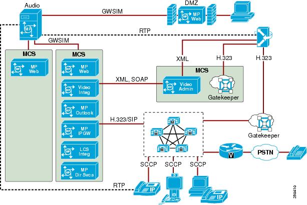
The single-site deployment is the base deployment, with all server components and users located at a single site interconnected by a single LAN (see Figure 15-1). In this model, Unified MP is co-located with the Unified CM cluster and integrated via H.323 or SIP, as described in sections on H.323 and SIP Integration with Unified MP, and Gatekeeper Integration.
Single-site deployments can include integrations such as Unified MP for Outlook, Unified MP Video Integration, Directory Services, and LCS integration. External web conferencing access is made available by configuring Segmented Meeting Access (DMZ deployment) as described in the section on DMZ Deployment. Within a single-site, web conferencing servers can be configured in both internal and external clusters for increased capacity and redundancy.
Figure 15-1 Single-Site Unified MP Deployment
The shaded area in Figure 15-1 represents the Cisco Media Convergence Server (MCS), on which one or more Cisco Unified MeetingPlace components can be installed. Video Administration is the only component that must be installed on a dedicated MCS. For detailed information on these components, see the section on Cisco Unified MeetingPlace Components.
Multisite Unified MP Deployment
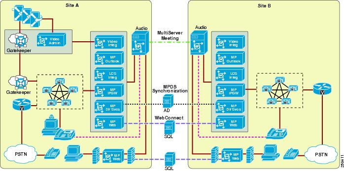
The multisite deployment model connects multiple single-site Unified MP systems using the WebConnect, Multiserver Meeting, and Directory Services features. (See Figure 15-2.)
•
WebConnect provides rollover capability among sites for scheduling, and it requires web servers to share the same SQL database.
•
•
MeetingPlace systems in a multisite deployment each have their own separate phone number and audio server databases. Audio servers are not clustered in any way. Unified MP Web servers can be load balanced and clustered only within each site. Sites can be co-located or geographically dispersed.
Figure 15-2 Multisite Unified MP Deployment
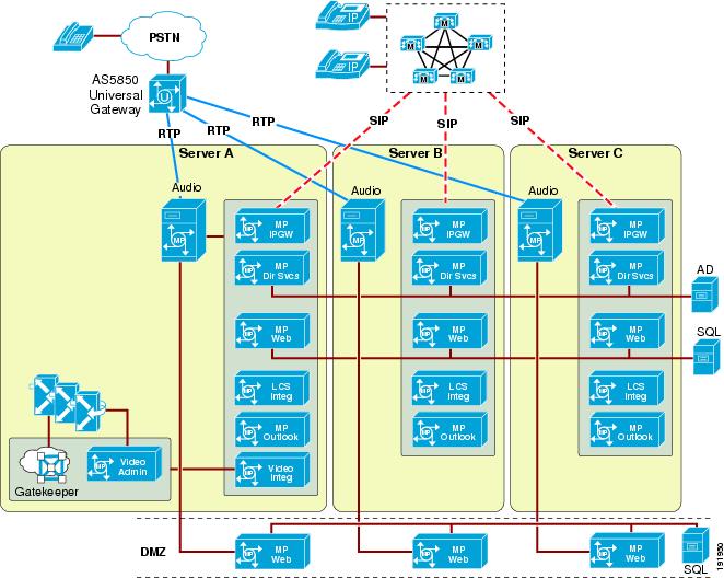
Reservationless Single-Number Access Deployment
Reservationless single-number access (RSNA) is the concept of using one access number to access multiple Unified MP reservationless systems. The RSNA feature enables multiple Unified MP Audio servers that share the same SQL database to appear as one server to the user community. Regardless of where the end user's profile is located, Unified MP will automatically transfer the end user to the appropriate server after their profile number or meeting ID is entered. With RSNA implemented, the reservation or scheduled meeting option becomes unavailable. RSNA is required under the following conditions:
•
•
•
Figure 15-3 illustrates an RSNA deployment.
Figure 15-3 Reservationless Single-Number Access Deployment
Design Considerations for RSNA
•
•
•
–
–
•
DMZ Deployment
Cisco Unified MP supports the placement of a web collaboration server within the demilitarized zone (DMZ) for publicly listed meetings. External participants use this server for web collaboration, while internal participants use an internal web server for web collaboration. Audio from external participants comes into Unified MP either through a direct TDM trunk to the Audio Server or through a VoIP gateway (controlled by Cisco Unified CM) to a VoIP port on the Audio Server. Table 15-1 lists the ports that must be opened on the internal corporate firewall to allow communication between the DMZ web server and the various Unified MP components on the internal network.
This deployment option, referred to as Segmented Meeting Access (SMA), may be applied to any variation of the deployment models discussed previously in this chapter. SMA implementations require deployment of an internal web server. For more information on SMA, refer to the Cisco Unified MeetingPlace product documentation available at http://www.cisco.com.
H.323 and SIP Integration with Unified MP
Unified MP integrates with Unified CM through the Unified MP IP Gateway. This gateway can integrate directly via H.323 or SIP between Unified CM and the Unified MP IP Gateway (see Figure 15-4). With this implementation, the dial plan with respect to Unified MP is relatively simple. Unified MP is referenced via a route pattern defined on Unified CM, which points to the H.323 gateway or SIP trunk. All other dial plan configuration is handled through Unified CM and possibly a gatekeeper if Unified CM is connected to a gatekeeper.
Figure 15-4 Direct Integration Through H.323 or SIP
The Cisco Unified MP 6.x Web Conferencing server has two network interface controllers (NICs) that have different IP addresses. One interface is used for Web Administration and the other is used for flash-based media collaboration. In a co-resident setup where both the Unified MP Web Conferencing server and the Unified MP IP Gateway are installed on the same Cisco Media Convergence Server (MCS), two VoIP gateway devices (H.323 or SIP) must be configured in Unified CM and be associated to each IP address of the MCS. If only one gateway device is configured in Unified CM, all call signaling and RTP packets are sourced from the IP address of the NIC with lower binding priority, which could lead to potential call failures.
H.323
Because it defines Unified MP as an H.323 gateway on Unified CM, H.323 integration is the preferred implementation at this time. This method has the following characteristics:
•
•
SIP
SIP integration is done by defining a SIP trunk on Unified CM and Unified MP. Unified MP 6.x supports SIP delay-offer, thus a static media termination point (MTP) is optional with all calls across a SIP trunk between Unified CM and Unified MP. A separate SIP Trunk Security profile must be created, with the outbound transport type set to UDP and associated with the SIP trunk to Unified MP. The SIP trunk has the same capabilities listed above for H.323.
Gatekeeper Integration
Cisco Unified MP can be integrated into a gatekeeper environment by either of the two methods detailed in this section. The addition of video support to Unified MP adds more complex gatekeeper requirements, which are outlined in the section on Video Gatekeeper Integration.
Unified MP can register directly with a gatekeeper as a terminal (see Figure 15-5). The primary E.164 address defined in the Unified MP system is used when registering. Additional E.164 addresses for direct-dial meetings must be assigned statically in the gatekeeper. This model has some additional redundancy because the gatekeeper is able to route outbound calls to multiple nodes. Because Unified MP registers with the gatekeeper by using a single E.164 address, extra configurations may be needed so that any abbreviated dialing expansion or digit manipulation can be resolved to that single E.164 address.
Figure 15-5 Gatekeeper Integration
In a Unified CM environment, the following considerations apply to the gatekeeper integration:
•
•
Call Admission Control, QoS, and Bandwidth
Call admission control, Quality of Service (QoS), and proper bandwidth allocation are the main mechanisms to ensure voice and video quality. This section describes how these mechanisms apply to Unified MP.
Call Admission Control
Call admission control with Unified MP should be treated the same as call admission control with a Cisco IP Telephony gateway. Unified MP acts like a gateway connected via a gatekeeper, directly via H.323, or via a SIP trunk. For the most effective call admission control implementations, the Unified MP Audio Server and IP Gateway components should be co-located.
For further information regarding call admission control strategies, refer to the chapter on Call Admission Control, page 9-1.
QoS Markings
Unified MP Audio Server
RTP media from the Audio Server is marked EF (DSCP 0x2E) by default. GWSIM traffic to and from other Unified MP components is not marked.
Unified MP IP Gateway Signaling
H.323 and SIP signaling traffic from the IP Gateway is not marked. Signaling traffic from Unified CM to the IP Gateway is marked CS3 (DSCP 0x18) by Unified MP. If the IP Gateway is co-located with Unified CM, the lack of signal marking will not be an issue unless congestion is present in the locally switched network. For implementations with these components remote from each other, additional configuration may be needed to re-mark signaling traffic on the edge devices.
Bandwidth
Web Collaboration Bandwidth
Web collaboration is the largest bandwidth consumer, and this traffic becomes especially significant for remote users across WAN links. Users at remote sites that cause web collaboration to traverse a WAN will require special consideration. The client flash session bandwidth or room bandwidth setting for these users should be lowered, reducing the load across the WAN. Because web collaboration data is delivered unicast, the largest burst of data should be multiplied by the number of clients at a remote site. For example, assume a remote site has 100 users, 10 of which are on a web collaboration session at any one time. If bursts of 1.5 Mbps occur in the data from the remote server to each user, 15 Mbps bursts can be experienced across the WAN connection.
When WAN links become congested from excessive web collaboration data or other sources, the degradation of all traffic is compounded by packet loss, retransmissions, and increased latency. Sustained congestion will have a sustained degrading impact on all remote collaboration sessions. The following settings on the client web collaboration sessions control the rate at which the participant receives data as well as the rate at which the presenter sends data:
•
•
•
Bandwidth bursts above 1,500 kbps are possible if high-resolution images or photos are shared. Sharing normal to complex presentations or documents should not generate bursts above 1,500 kbps unless large complex images are embedded. Bandwidth settings are not automatically adjusted when congestion occurs; they must be adjusted manually. Bandwidth settings default to LAN and must be set at the initialization of each collaboration session. A new session is set to LAN regardless of previous settings.
Audio Bandwidth
Audio traffic consists of Real-Time Transport Protocol (RTP) traffic flowing to and from the Unified MP Audio server. Both G.711 and G.729 codecs are supported with Unified MP. Capacity on Unified MP is not affected by the codec chosen, but voice quality on Unified MP can be reduced by using a compressed codec such as G.729. In a voice conference, a G.711 voice session uses 80 kbps and a G.729 voice session uses 24 kbps.
Call Control Bandwidth
Call control bandwidth is extremely small but critical. Co-locating the Unified MP IP Gateway component with Unified CM or the gatekeeper helps protect against issues with call control. Remote locations need proper QoS provisioning to ensure reliable operation.
GWSIM
GWSIM traffic flows between the Unified MP Audio server and other Unified MP components, including the Unified MP IP Gateway and Unified MP Web.
Traffic between the Unified MP Audio Server and the Unified MP IP Gateway components is minimal but important traffic. Placing the Audio Server and IP Gateway components in the same location helps ensure proper operation. Separation of components by a WAN would require proper QoS provisioning to ensure reliable operation.
Traffic between the Unified MP Audio Server and Unified MP Web includes some database synchronization and might therefore at times be bursty in nature, but this traffic is not real-time.
Directory Integration
With read access to the corporate directory, the Unified MP Directory Service gateway can synchronize profiles on all Unified MP systems. A Unified MP Directory Service gateway is required for each Unified MP Audio server being implemented. In an environment with multiple Unified MP Audio servers, multiple Unified MP Directory Service gateways must be implemented to keep user profiles in synchronization with the multiple Unified MP Audio servers. This synchronization is required when the Web-Connect feature is used to provide transparent scheduling redundancy across multiple Unified MP systems.
In a single-site Unified MP deployment, one of the Unified MP Directory Service gateways can be designated as a master. This master gateway is responsible for reading and pulling profile information from corporate directory servers via LDAP. All the other Unified MP Directory Service gateways (slaves) will synchronize and read profile information from the master gateway. In a multisite Unified MP deployment, each Unified MP Directory Service gateway should integrate directly with its local corporate directory server. The Unified MP Directory Service gateway supports the following directory servers:
•
Microsoft Active Directory enables you to store, access, and manipulate organizational information about users and resources, and manage all elements of a networked environment, such as computers, groups, users, policies, and other user-defined objects.
•
Netscape, SunOne, and iPlanet are general-purpose LDAP directories that store, publish, and centrally manage users and network resources.
•
Synchronizations of user data from the Unified CM directory enable the Unified MP system to support Cisco Unified Communications users who are configured in Unified CM.
For details about the Directory Services component, refer to the Administration Guide for Cisco Unified MeetingPlace Directory Services, available at http://www.cisco.com.
Cisco WebEx Integration
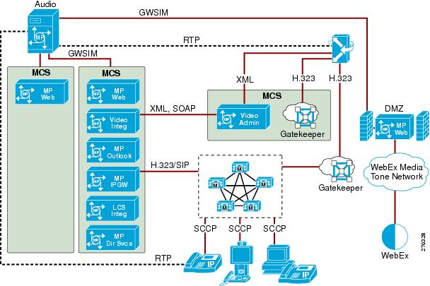
Unified MP users can choose Cisco WebEx as the web conferencing provider when scheduling a Unified MP meeting. Cisco WebEx integration is available in Cisco Unified MP 6.0.2 and later releases. The voice and video conferencing are still provided by Unified MP. Voice and video dial-in information must be provided to WebEx users in order for them to join the meeting, or they can use the outdial feature that is available in WebEx to join the meeting.
Figure 15-6 shows the integration between Unified MP and the WebEx Media Tone Network. The Unified MP Web server must be deployed within a DMZ to provide this integration. All service requests are exchanged and processed via application programming interface (API) calls between the Unified MP Web server within the DMZ and the WebEx Media Tone Network. When a user joins a WebEx conference, Unified MP first authenticates the user then takes the user's request to the Unified MP Web server in the DMZ and redirects it to the WebEx Media Tone Network. This redirect behavior is completely transparent to the Unified MP user.
Figure 15-6 Cisco Unified MP and WebEx Integration
Unified MP Video Integration
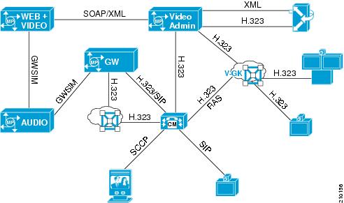
This section discusses the impact on system design due to Unified MP Video, and primarily due to the Video Administration component. In this chapter, the term Unified MP Video refers to the entire video system, including Video Administration, the Video Integration component, MCUs, gatekeepers, endpoints, and Unified CM. (See Figure 15-7.) One component of the system is the Video Integration component, which resides on one or more Unified MP Web Conferencing servers. Some other Unified MP documents refer to Video Integration as the entire video system, and this difference will be noted where possible when referencing those documents.
Figure 15-7 Cisco Unified MP Video Integration
Video Administration
Video Administration controls all aspects of video conferencing and interfaces with MCUs, gatekeeper, Unified CM, and other Unified MP components. Video Administration is the main control point for all incoming and outgoing video calls, and it makes all decisions regarding resource utilization and cascading of resources. In addition to basic MCU cascading to increase conference size, Video Administration can intelligently select which MCU to use based on internally defined locations for each participant. Multisite video meetings can result in cascading MCUs local to user groups, thus creating one link across a WAN between cascaded MCUs.
Video Administration has the following characteristics:
•
•
•
•
•
•
•
•
•
•
•
•
•
•
•
•
Video Call Admission Control, QoS, and Bandwidth
Call admission control, Quality of Service (QoS), and proper bandwidth allocation are the main mechanisms to ensure voice and video quality. This section describes how these mechanisms apply to Unified MP Video.
Video Call Admission Control
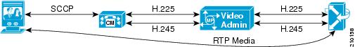
Video Administration is the routing point for all MCUs, and it determines on which MCU each call terminates. As shown in Figure 15-8, all H.225 and H.245 signaling terminates on Video Administration:
•
•
•
Figure 15-8 Video Administration Signaling Termination
Because of this functionality, visibility beyond Video Administration for any current call admission control mechanism is not possible. Video Administration is seen as the terminating endpoint to all call admission control mechanisms.
Implementation of call admission control with MCUs distributed across multiple sites becomes a challenge. Currently the only call admission control capabilities for distributed MCUs are implemented separately within Video Administration and do not tie into any other mechanism in any way. This is an independent, standalone call admission control mechanism for use only with Video Administration MCUs. It is not an optimal way to implement call admission control but is the only available option for this release of Cisco Unified MeetingPlace.
Implementation of call admission control via the Video Administration component is detailed in the Administration Guide for Cisco Unified MeetingPlace Video Integration, available at http://www.cisco.com.
Note
Video QoS
The following traffic markings apply call control, media, and other flows:
•
•
•
•
•
For components separated by WAN links, re-marking may be needed to ensure reliable operation. For further information regarding video QoS, refer to the chapter on IP Video Telephony, page 17-1.
Video Bandwidth
See the chapter on IP Video Telephony, page 17-1, for current information regarding video bandwidth.
Video Gatekeeper Integration
With Unified MP, Video Gatekeeper is required to outdial video calls from Video Administration to video endpoints, regardless of the type of endpoint. This requirement, among other changes with Unified MP Video, significantly impacts the way Unified CM, Unified MP, and Video Gatekeeper interact in this environment. The following sections detail relevant subjects involving Video Gatekeeper and its critical role in the deployment of video with Unified MP.
This section assumes Video Administration uses Video Gatekeeper to route all outbound calls through Unified CM. Integration of Video Administration into an infrastructure gatekeeper environment, bypassing Unified CM, is another deployment option not covered here due to the focus on endpoints controlled by Unified CM.
This section covers the following topics:
•
Basic concepts of how H.323 video endpoints interact with Video Gatekeeper.
Description of how a via-zone gatekeeper operates.
•
Overview of how Video Administration and Video Gatekeeper interact and process inbound and outbound calls.
•
Additional steps to ensure proper call resolution within Video Gatekeeper for outbound calls from Video Administration.
•
Critical information regarding redundancy groups and gatekeeper zone configuration of H.323 video endpoints defined on Unified CM.
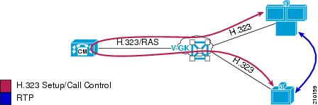
H.323 Video Endpoints and Video Gatekeeper
For deployments incorporating H.323 video endpoints, a separate video endpoint gatekeeper is recommended. (See Figure 15-9.) This gatekeeper should be set up as a via-zone gatekeeper, as explained below. Setup of this nature ensures that every call between H.323 video endpoints and any other video endpoint or termination point (SIP, SCCP, Unified MP Video Administration, or other H.323 video endpoints on the same gatekeeper) are handled by Unified CM for digit manipulation, dialing restrictions, and call admission control.
Figure 15-9 Video Endpoints and Video Gatekeeper
Via-Zone Video Gatekeeper
The via-zone gatekeeper can be a complex concept, but the following points present a very simplified way of looking at it and the easiest way to understand the basic operation in this environment:
•
•
•
•
Note
Video Administration and Video Gatekeeper Overview
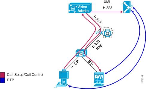
Video Administration requires the use of a gatekeeper to resolve outbound calls. Video Administration sends Location Request (LRQ) messages to this gatekeeper while not registering in any way to that gatekeeper. (See Figure 15-10.) This behavior differs greatly from previous Unified MP versions.
Figure 15-10 Video Administration and Video Gatekeeper
In Figure 15-10, an outbound call is placed to a SIP video endpoint controlled by Unified CM. This example is a simplified illustration of basic call flow but is not a detailed or complete example of call flow for outbound calls. For a detailed explanation of call flows, see the section on Video Call Flows.
In a Unified CM environment that contains a Video Gatekeeper for H.323 video endpoints, the logical choice is to use Video Gatekeeper to route all calls through Unified CM. Sending outbound calls to Video Gatekeeper routes calls through Unified CM and applies dial plan restrictions, digit manipulation, and call admission control.
Calls inbound to Unified CM (outbound from Video Administration) are resolved via Video Gatekeeper to a particular Unified CM node. H.225 setup is then sent from Video Administration to that Unified CM node. The H.323 trunk and Registration Admission Status (RAS) Aggregator to Video Gatekeeper are critical for using Unified CM to provide dial plan restrictions, digit manipulation, and call admission control.
Calls outbound to Video Administration (inbound from Unified CM) are resolved via dial pattern matches associated with the defined H.323 trunk that points to the video gatekeeper.
Additional Video Gatekeeper Configuration Requirements
With the use of a via-zone gatekeeper to resolve outbound calls from Video Administration, some additional configuration may be necessary to ensure proper call resolution.
When Video Administration attempts to resolve an outbound call, it begins by sending an LRQ to Video Gatekeeper. This LRQ is resolved to Unified CM for all outgoing calls, based on Video Gatekeeper being a via-zone gatekeeper as discussed previously. For a detailed explanation of the call flow, see the section on Video Call Flows.
One scenario, however, can cause Video Gatekeeper to resolve to something other than Unified CM. If zone prefixes are not used in the Video Gatekeeper and the outdialed number from Video Administration matches exactly with an E.164 address registered to the Video Gatekeeper, the call will bypass Unified CM and complete directly to that endpoint. This behavior occurs regardless of the zone in which the endpoint is registered. To resolve this issue, you can add a hopoff statement to Video Gatekeeper to resolve all LRQs to Unified CM via an intercluster trunk. This method should be implemented on endpoint via-zone gatekeepers only. The hopoff will send all calls to a particular zone regardless of origin or destination. (The example below illustrates use of the hopoff statement.) If zone prefixes are used on the Video Gatekeeper, this scenario does not occur.
The following notes apply to the example below, which shows a simplified Video Gatekeeper configuration:
•
•
•
•
Gatekeeperzone remote video-admin cisco.com 10.2.2.2 invia ccmtrunk outvia ccmtrunkzone local video-ep cisco.com 10.1.1.1 invia video-ep outvia video-ep enable-intrazonezone local ccmtrunk cisco.com invia ccmtrunk outvia ccmtrunk enable-intrazonesend-cisco-circuit-infogw-type-prefix * hopoff ccmtrunk default-technologylrq forward-queriesno use-proxy video-ep default inbound-to terminalno use-proxy video-ep default outbound-from terminalno use-proxy ccmtrunk default inbound-to terminalno use-proxy ccmtrunk default outbound-from terminalFigure 15-11 Gatekeeper Configuration Example
Zones and RASAggregator Redundancy Groups with H.323 Video Endpoints on Unified CM
Unified CM redundancy groups (Unified CM groups and device pools) can be defined for H.323 video endpoints to allow failover to another node if the primary node fails. Improper configuration of H.323 video endpoints on Unified CM with respect to these redundancy groups can easily cause call failure.
When you configure H.323 video endpoints on Unified CM, you define a gatekeeper and a zone in addition to a redundancy group. Unified CM registers a single RASAggregator Trunk from the highest priority node listed in the chosen redundancy group. Improper configuration that allows two nodes to register RASAggregator Trunks to the same gatekeeper zone will cause call routing issues and call failure.
The following sections describe the possible configuration scenarios.
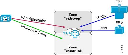
One Zone and One Redundancy Group
In the most straightforward scenario, all the H.323 video endpoints have the same redundancy group and use the same gatekeeper zone (see Figure 15-12). One RASAggregator Trunk is registered in the single endpoint zone. This configuration ensures proper operation, with no call loss due to mis-routing.
Figure 15-12 One Zone and One Redundancy Group
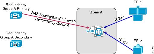
Multiple Zones and One Redundancy Group
In this scenario, H.323 video endpoints can be defined in Unified CM to be in different zones on the same video gatekeeper (see Figure 15-13). Two RASAggregator Trunks are registered in the two separate endpoint zones. Again this ensures proper operation, with no call loss due to mis-routing.
Figure 15-13 Two Zones and One Redundancy Group
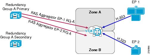
Multiple Zones and Multiple Redundancy Groups
This scenario should be avoided, if possible, due to the complexity that it adds (see Figure 15-14). Improper configuration can easily lead to failed calls.
Figure 15-14 Two Zones and Two Redundancy Groups
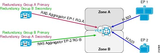
Incorrectly Configured Redundancy Groups Cause Failures
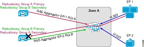
Note
Figure 15-15 shows an incorrect configuration of two different redundancy groups registered to the same endpoint zone. This configuration will cause call failures.
Figure 15-15 Incorrect Configuration of One Zone and Two Redundancy Groups
As shown in Figure 15-15, if two endpoints in the same zone use different redundancy groups with different primary Unified CMs, two RASAggregator Trunks will be registered to one zone from different nodes, thus causing the gatekeeper to load-balance between these two trunks. In this case, some calls will be sent across incorrect RASAggregator Trunks and will fail.
Video Call Flows
This section shows examples of call flows for inbound and outbound video calls with Unified MP configured.
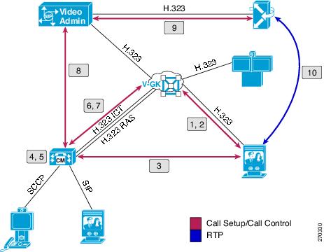
Inbound Call from an H.323 Video Endpoint
Figure 15-16 illustrates the flow for this call scenario, which involves the following sequence of events:
1.
2.
3.
4.
5.
6.
7.
8.
9.
10.
Figure 15-16 Video Call Flow Into Video Administration
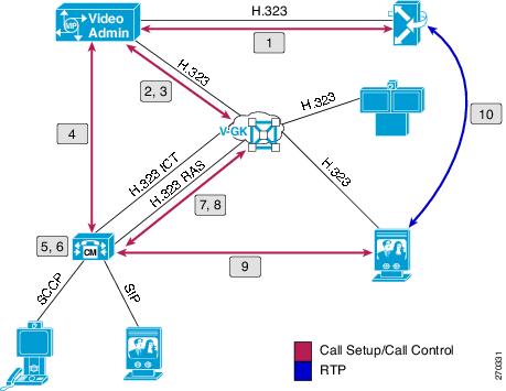
Outbound Call to an H.323 Video Endpoint
Figure 15-17 illustrates the flow for this call scenario, which involves the following sequence of events:
1.
2.
3.
4.
5.
6.
7.
8.
9.
10.
Figure 15-17 Video Call Flow Out of Video Administration
Video Dial Plan
With the video component, video participants dial a prefix and meeting ID as a single dialed number. Because of the incorporated meeting ID, this dialed number is unique per conference and can be of fixed length with fixed-length meeting IDs or of variable length with variable-length meeting IDs.
Example:
Video prefix 72
Meeting ID 43221Dial-in number 7243221
The video dial-in number for the specific meeting is incorporated into the notifications sent to users, the scheduled meeting information in Cisco Unified MeetingPlace Web, and the Connect box within the web collaboration session. Dial-out from the web collaboration session is also available to connect video endpoints.
Fixed-length meeting IDs ensure a fixed-length dialed number. They are very easy to implement from the standpoint of Unified CM, and they have the least impact to users. The use of vanity IDs, however, is not available with this method.
Variable-length meeting IDs become a challenge due to the unknown length of the dialed number. This factor can cause the need for multiple route patterns in Unified CM to accommodate the various possibilities. Some scenarios (detailed in Variable-Length Meeting IDs) might require the user to wait for inter-digit timeout to occur before the call is placed.
Fixed-Length Meeting IDs
Restricting meeting IDs to one specific length eliminates issues associated with variable-length meeting IDs and allows for a simple, clean video dial plan implementation. Only one specific route pattern is needed in Unified CM, which will match and process all dialed numbers from video participants immediately.
Example:
Video prefix 72
Meeting ID 43221Route pattern 72XXXXX
Variable-Length Meeting IDs
The following example shows meeting IDs of different lengths and how they impact route pattern implementation and operation.
Video prefix 72
Meeting ID #1 43221
Meeting ID #2 5256
Multiple exact route patterns:
Pattern 1 72XXXX
Pattern 2 72XXXXX
With this example, dialing into Meeting 1 (7243221) will connect immediately due to an exact match of Pattern 2, with no other possibilities. Dialing into Meeting 2 (725256) will cause the call to be delayed by inter-digit timeout due to the possibility of another longer match. Upon timeout, Pattern 1 is matched and the call is connected.
Universal route pattern:
Pattern 1 72!
With a single route pattern for all dialed numbers of any length, the inter-digit timeout must expire for every call placed. This is a simpler implementation because it does not depend on meeting ID length.
In addition, a second pattern can be added with a terminating # to give users the option of terminating the dialed number:
Pattern 1 72!
Pattern 2 72!#
If the dialed number is terminated by #, the inter-digit timeout is not a factor and the call is processed immediately. Calls not terminated by # will be subject to the inter-digit timeout.
Note
Redundancy and Load Balancing
This section describes redundancy and load balancing considerations for the following MeetingPlace components:
•
Unified MP Audio Server
If the Unified MP Audio Server fails, calls in progress will be dropped. If the Audio Server is unreachable by the Unified MP IP Gateway, the IP Gateway will immediately reject any incoming calls. There is no automatic failover mechanism available for the Unified MP Audio Server.
Disaster Recovery
A disaster recovery plan provides for orderly restoration of the database, computing, and services. The plan usually includes the following provisions:
•
•
•
•
A component called the Unified MP Network Backup Gateway enables system mangers to transfer multiple copies of the Unified MP database (audio configuration files and scheduled meeting information) from the Audio Server to a designated storage server on the network. Files are encrypted for security. A maximum of three Network Backup Gateways per system can be implemented, but only one of them can make the database transfer at a time.
Redundancy
If two or more Unified MP Audio Servers are deployed, any of the following plans for redundancy can be implemented:
•
A shadow server is a redundant Unified MP Audio Server that is not active until the primary Audio Server fails. During the disaster, the shadow server must be switched from shadow mode to active mode using the command line interface (CLI). Once active, the shadow server can store only limited information, such as profile information, meeting information (past, present, and future), and participant information. Recording, attachments, hardware and network configuration, and automatic software upgrades are not available on the shadow server. The shadow server has the following network connectivity requirements:
–
–
–
•
In this plan, two Unified MP Audio Servers are active production servers, and each one can overflow to the other. Profiles are synchronized automatically between the servers through the Directory Services. Automatic failover between the two Audio Servers does not occur. Meetings have to be uploaded to the remaining server during an emergency, and users must rejoin the meetings manually. On Unified CM, you can configure route groups and route lists so that if one Unified MP Audio Servers fails, the calls will be routed to the other active Audio Server.
•
In this plan, a Unified MP Audio Server is implemented with a set of critical meetings pre-created and always available. This deployment is suitable for any crisis management application, with features such as blast outdial to crisis management teams.
Unified MP IP Gateway
The following redundancy and load balancing considerations apply to the Unified MP IP Gateway.
Redundancy
If the Unified MP IP Gateway fails, calls in progress will be dropped.
Two or more Unified MP IP Gateways can connect to the same Unified MP Audio Server. There are two methods for implementing redundancy, one with and one without a gatekeeper.
•
–
–
Figure 15-18 Redundancy Without a Gatekeeper
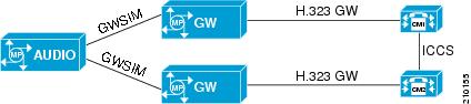
•
Calls outbound from Unified MP that are sent to the gatekeeper may be directed to alternate Unified CM nodes in the event of a Unified CM failure. This is an advantage over direct outbound configuration on a single Unified MP IP Gateway, which allows only one destination node to be configured. This method also provides quick failover processing. The Unified MP IP Gateway registers with the gatekeeper as a terminal device by default. The gatekeeper does not allow multiple terminal devices to register with the same E.164 ID. In order to have multiple Unified MP IP Gateways registered with the gatekeeper, the Unified MP IP Gateways must be configured as gateway devices for their RAS registrations. For information on this topic, refer to the Cisco Unified MeetingPlace product documentation available at http://www.cisco.com.
Figure 15-19 Redundancy With a Gatekeeper
Load Balancing
For dial-in load balancing, you can use either of the following same approaches for redundancy:
•
•
As explained in the previous section, load balancing for outdialing is done only among those Unified MP IP Gateways that never have outdial failures.
Unified MP Web Conferencing Server
The following redundancy and load balancing considerations apply to the Unified MP Web Conferencing Server.
Redundancy
A Unified MP Web Conferencing server cluster can be used to provide redundancy. The Unified MP Web Conferencing cluster contains up to three web conferencing servers that all connect to one Unified MP Audio server and share the same SQL database. The Unified MP Web Conferencing cluster can be either internal or external. An internal cluster means that all web conferencing servers are implemented behind the corporate firewall and provide full access (scheduling and attending meetings) to end-users. An external cluster means that all web conferencing servers are implemented inside a DMZ and provide attend-only access to end-users. Both internal and external clusters can be deployed at the same time, but they utilize two different SQL databases. If one web conferencing server becomes unavailable, meetings will fail-over to other servers within the cluster and user will not experience any meeting interruptions.
Load Balancing
A Unified MP Web Conferencing server cluster can also be used to provide load balancing. The Unified MP Audio server will check the load on all three web conferencing servers within the cluster and will assign the user to the server with the least load.
Video Integration Component
The Video Integration component resides on all Cisco Unified MP Web servers, but it can be active on only a single server, enabling that server as the web collaboration server for all conferences involving video. No automatic failover mechanisms exist for the Video Integration component. Failure of the supporting server would require manual intervention to configure and enable Video Integration on another Unified MP Web server.
Video Administration
Video Administration is limited to server component redundancy, and it does not have any software-level redundancy. Only one Video Administration server may be implemented per Unified MP deployment. The server on which Video Administration is deployed should contain redundant components to minimize risk of downtime.
Video Gatekeeper
Video Gatekeeper is no different than a standard gatekeeper with respect to redundancy abilities. In a Unified MP environment, however, some special considerations must be taken into account. Of the following techniques for gatekeeper redundancy, only HSRP is fully compatible with this environment.
Gatekeeper HSRP
Redundancy via Hot Standby Router Protocol (HSRP) provides for outbound calling redundancy from Video Administration. If the primary gatekeeper fails, call resolution requests are automatically sent to the backup gatekeeper. Video Administration does not need to know about the backup gatekeeper or primary gatekeeper state to accomplish this failover.
Gatekeeper Clustering and Alternate Gatekeeper
With the gatekeeper clustering and alternate gatekeeper methods, an issue arises with outbound calls from Video Administration. Outbound calls from Video Administration are sent to the Video Gatekeeper without any registration to that gatekeeper. This prevents Video Administration from being aware of the gatekeeper state and alternate gatekeeper existence. Video Administration will continue blindly to send calls to the failed gatekeeper in this environment.
Capacity and Sizing
This section discusses capacity and sizing of Unified MP audio, web, and video conferencing.
Unified MP Audio Conferencing
Cisco recommends the following two methods for calculating Unified MP audio conferencing capacity.
Calculation Based on Number of Employees
For this method, calculate the Unified MP audio capacity as follows:
•
•
For example, in a system with 540 total employees, including 500 regular employees and 40 knowledge workers, you should provision 12 (10+2) audio ULs.
Calculation Based on Number of Minutes
If you know the actual voice conferencing usage (minutes per month), use Table 15-2 to calculate the Unified MP audio conferencing capacity.
For example, a customer using 500,000 minutes per month for audio conferencing will need 250 Unified MP audio ULs to accommodate 250 Unified MP audio conferencing participants. To calculate the number of ULs needed, take the number of voice usage minutes per month (500,000) and divide by the baseline minutes per UL per month, which in this case is 2,000 minutes.
For both calculation methods mentioned above, Cisco recommends over-provisioning the Unified MP audio ULs by 20% for peak hour usage and another 20% for year-after-year growth.
Table 15-3 lists the number of concurrent audio conferencing user licenses (ULs) supported on the Cisco Unified MeetingPlace 8106 and 8112 Audio Server platforms.
Note
Unified MP Web Conferencing
A single standalone web conferencing server can support up to 500 web user licenses (ULs), or 500 Unified MP web conferencing participants. One Unified MP Web Conferencing server can support one web conference with 500 participants or 10 web conferences with 50 participants each. A Unified MP Web Conferencing Server cluster can contain up to three servers, so the maximum number of web ULs per cluster is 1,500. If Secure Socket Layer (SSL) Transport Layer Security (TLS) is implemented for Unified MP web conferencing, the number of ULs supported per server decreases to 330 and the number of ULs supported per cluster decreases to 990.
Note
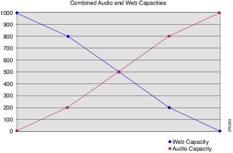
Cisco does not support audio conferencing on any Cisco Unified MP implementation that has 1,000 or more web conferencing ULs. Figure 15-20 shows combined Unified MP audio and web conferencing capacities. Cisco supports a total of 1,000 combined audio and web conferencing ULs. For example, for an existing Cisco Unified MP system that has 800 audio ULs, up to 200 web conferencing ULs can be provisioned.
Figure 15-20 Combined Audio and Web Capacities
Unified MP Video Conferencing
Unified MP Video Conferencing capacity is based entirely on the MCU resources that are managed by Video Administration. A Cisco Unified Videoconferencing 3545 MCU platform can have up to three Enhanced Media Processors (EMPs). An EMP is a video processing card that can support up to 48 standard-rate video ports (up to 384 kbps) or 24 high-rate video ports (up to 2 Mbps). One video port can support one video conferencing participant. With three EMP cards installed, the Cisco Unified Videoconferencing 3545 MCU provides 144 standard-rate video ports or 78 high-rate video ports.
Cisco Unified Videoconferencing 3515 platforms have only fixed video port support. The Cisco Unified Videoconferencing 3515-MCU12 supports 18 standard-rate video ports or 12 high-rate video ports; the Cisco Unified Videoconferencing 3515-MCU24 supports 36 standard-rate video ports or 24 high-rate video ports.