Downloads |
 Feedback Feedback
|
Table Of Contents
Cisco BTS 10200 Softswitch in the PacketCable Network
Description of the Event Message Feature
Event Message Generation Details and Content
Timestamp Support for Event Messages
Event Message Storage on the CA
PCMM-Based QoS for Type 1 Clients
SOAP/XML Interface for CMS Subscriber Provisioning
Prerequisites for CMS Subscriber Provisioning
Limitations On CMS Subscriber Provisioning
Provisioning Basic PacketCable and DQoS Features
Provisioning the CMS Interfaces to the CMTS and eMTA
Provisioning DQoS Parameters for Codec Negotiation Service
Provisioning TGCP Interfaces to TGWs
Provisioning the Keepalive AUEP and ICMP Ping Options
Provisioning MGCP Command Timeout and QoS Parameters
Provisioning the Aggregation ID Subnet
Provisioning CMTS Discovery Using the Static Subnet Table
Provisioning Subscriber ID Parameters and DQoS Measurement Counter
Provisioning Security Interfaces
Provisioning Parameters for Secured Media
Provisioning Security Interfaces to the MTA
Provisioning Security Interfaces to the CMTS
Provisioning Security Interfaces to the TGW
Provisioning Security Interfaces to the RKS
Provisioning IPsec Security Associations and Ciphersuite Algorithms
Provisioning Support for EM Transmission and Storage
Provisioning the System to Generate EMs for Billing
Provisioning Media_Alive Verification for EMs
Provisioning PCMM-Based QoS for Type 1 Clients
Provisioning AuditConnection Parameters
Operations, Billing, and EM Transfer Procedures
PacketCable Billing Data and Formats in Deployments Using CDBs
Reset, Control, and Status Commands
Manual Recovery and Transfer of Stored EMs
Sending Billing Files to the RKS via FTP
Content of EMs Sent to the RKS
Viewing Media_Alive Verification for EMs
Creating Reports and Displays of Measurements
Measurements for the DQoS Feature on COPS Interface
Measurements for the EM Feature
Events and Alarms Specific to PacketCable-Based Network Elements and PCMM Features
Events and Alarms for the EM Feature
Events and Alarms for the Security Interface Feature
EM Generation Details and Content
PacketCable and Event Message Provisioning and Operations Guide, Cisco BTS 10200 Softswitch, Release 5.0
Revised: May 2010, OL-12264-08This document describes how the Cisco BTS 10200 Softswitch implements PacketCable-based interfaces and functions. It also provides provisioning and operating information for PacketCable features and event messages (EMs). It is intended for use by service provider management, system administration, and engineering personnel who are responsible for designing, installing, provisioning, and maintaining networks that use the Cisco BTS 10200 Softswitch system in a PacketCable-based network.
Feature History
Release 5.0
Version OL-12264-08:
•
Updated the "Event Message Transport" section.
Release 5.0
Version OL-12264-07:
•
Release 5.0
Version OL-12264-06:
•
•
Release 5.0
Version OL-12264-05:
•
•
•
Version OL-12264-04:
•
Release 5.0
Version OL-12264-03:
•
Version OL-12264-02:
•
•
•
•
Version OL-12264-01:
•
•
•
•
•
•
•
Contents
Operations, Billing, and EM Transfer Procedures
EM Generation Details and Content
Technical Overview
This section provides technical information about the implementation of PacketCable features. It covers the following topics.
•
•
•
Note
Cisco BTS 10200 Softswitch in the PacketCable Network
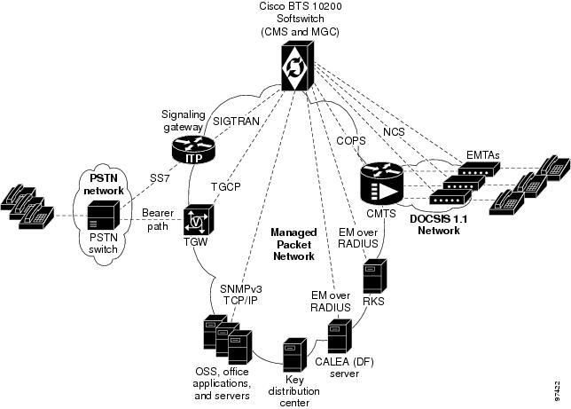
The Cisco BTS 10200 Softswitch is a class-independent network-switching element. In a PacketCable-based network, it functions as both a call management server (CMS) and a media gateway controller (MGC). It provides call control, call routing, and signaling for several types of multimedia terminal adapters (MTAs) and embedded MTAs (eMTAs), cable modem termination systems (CMTSs), and trunking gateways (TGWs) in PacketCable-based networks. It provides interfaces to record keeping servers (RKSs) and key distribution centers (KDCs). The Cisco BTS 10200 Softswitch also communicates with announcement servers, SS7-based signaling gateways, MGCP-based media gateways (MGWs), and Session Initiation Protocol (SIP) networks.
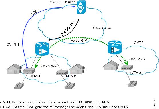
Figure 1 shows a typical network with PacketCable-based network elements and the applicable external interfaces of the Cisco BTS 10200 Softswitch. In the PacketCable-based network, the Cisco BTS 10200 Softswitch performs the functions of both the CMS and MGC. The Cisco BTS 10200 Softswitch also provides provisionable options for customizing the external interfaces.
Figure 1 Example of PacketCable-Based Network Architecture
PacketCable-Based Interfaces
The Cisco BTS 10200 Softswitch supports signaling on specific PacketCable-based interfaces shown in Figure 1. The following list summarizes the supported protocols for each of the links:
•
•
•
•
•
•
Additional interfaces are defined for the PCMM QoS features in the "PCMM-Based QoS for Type 1 Clients" section.
The SOAP/XML interface for CMS subscriber provisioning is defined in the "SOAP/XML Interface for CMS Subscriber Provisioning" section.
For a description of Cisco BTS 10200 Softswitch support for CALEA, see the Cisco BTS 10200 Softswitch System Description. For provisioning procedures related to CALEA support, see the Cisco BTS 10200 Softswitch Provisioning Guide.
Note
Additional Network Interfaces
The following additional interfaces are not part of the PacketCable feature set, but they provide other important functions useful in the service provider network:
•
•
•
–
–
•
This interface provides communication with Operations Support System (OSS) and office applications servers.Gate Coordination Functions
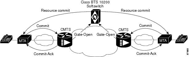
In the PacketCable environment, the Cisco BTS 10200 Softswitch performs the gate coordination functions of a CMS, including the gate controller (GC). GC signaling is based on the COPS stack. Each CMTS informs the CMS when a gate is successfully opened or closed. Two gate coordination messages are used, GATE-OPEN and GATE-CLOSE. Gate coordination is required to avoid several theft-of-service scenarios, as described in Appendix K of the PacketCable Dynamic Quality-of-Service Specification, PKT-SP-DQOS-I07-030815, August 15, 2003.
Note
GATE-OPEN Process
The normal coordination process for GATE-OPEN signaling, illustrated in Figure 2, has four main steps:
1.
2.
3.
4.
Figure 2 Gate Coordination Signaling Example (GATE-OPEN)
If the Gate-Open message arrives at the Cisco BTS 10200 Softswitch before it has sent a resource-commit request to the MTA, the Cisco BTS 10200 Softswitch sends a Gate-Delete message to the CMTS with Unexpected Gate-Open included in the reason code.
GATE-CLOSE Process
During a call, if the Cisco BTS 10200 Softswitch receives a GATE-CLOSE message from the CMTS, it allows the call to proceed on a best-effort basis, without a guaranteed level of service. (It tears down the call only when one of the parties in the call goes on-hook.)
Security Interface Features
Note
The implementation of PKT-SP-SEC-I09-030728, PacketCable Security Specification, July 28, 2003, provides a security scheme for the voice-over-cable network built on a set of security protocols. These protocols, based on the documents listed below, provide authentication (to help prevent theft of bandwidth, denial-of-service attack, replay, and so forth) and enable message integrity, privacy, and confidentiality.
•
–
–
•
–
–
The Cisco BTS 10200 Softswitch performs the security functions of a CMS and a MGC in the PacketCable environment. It supports security in accordance with PKT-SP-SEC-I09-030728 for both signaling and media:
•
•
The system supports IPsec features for encryption and authentication on specific PacketCable-based interfaces (see Figure 1). There are two aspects to the security features, the security protocol itself (IPsec), and the key management (Kerberos or IKE). The following list summarizes the supported security type for each of the links:
•
•
•
•
•
•
As shown in Figure 1, there is no interface between the KDC and the Cisco BTS 10200 Softswitch. To ensure secure NCS signaling, a dynamic key exchange is performed. This exchange provides for IPsec security operations between the MTA and the Cisco BTS 10200 Softswitch. (These procedures are described in the CableLabs document PacketCable Security Specification, PKT-SP-SEC-I09-030728, under "Kerberized IPsec" and other sections.)
•
•
Note
Note
Event Message Feature
This section describes Cisco BTS 10200 Softswitch support for the EM feature.
Billing Data Options
The Cisco BTS 10200 Softswitch can provision billing support using either of the following billing data generation methods:
•
•
The Cisco BTS 10200 Softswitch should be provisioned to generate either EMs or CDBs, but not both.
Caution
The content of the CDBs is outside the scope of this document. See the Cisco BTS 10200 Softswitch Billing Interface Guide for information about CDBs.
Description of the Event Message Feature
EMs are real-time data records containing information about network usage and activities. (They must not be confused with system event messages that report events and sometimes trigger alarms.) EMs are used in PacketCable networks to collect resource usage data for billing purposes. In the PacketCable architecture, EM generation is based on the half-call model. A single EM can contain complete usage data or it might contain only part of the usage information.
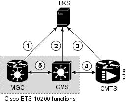
The Record Keeping Server (RKS) is a PacketCable network element that receives EMs from network elements, such as the call management server (CMS), media gateway controller (MGC), and the cable modem termination system (CMTS). The physical Cisco BTS 10200 Softswitch contains both CMS and MGC logical network elements. The EMs generated by both the CMS and MGC are sent to the RKS. The RKS correlates the information in multiple EMs and provides the complete record of service for a call, which is referred to as a CDR.
For information about EM-related operations on the Cisco BTS 10200 Softswitch, see the "Operations, Billing, and EM Transfer Procedures" section.
Figure 3 illustrates the PacketCable network elements that are involved in the EM process.
Figure 3 Event Message Interfaces
The EM related interfaces illustrated here are described as follows:
1.
2.
3.
4.
5.
PacketCable EMs can support billing and settlement activities for single-zone architectures. The originating and terminating CMSs exchange unique Billing Correlation IDs (BCIDs) and Financial Entity IDs (FEIDs) for each half of the call. The originating CMS sends a BCID and an FEID in the INVITE message. The Cisco BTS 10200 Softswitch allocates the BCID for calls it originates or terminates. Along with the FEID, the BCID is used across network elements to reference calls. The FEID is provisioned on a system-wide basis (a single setting for the Cisco BTS 10200 Softswitch) as defined in the "Provisioning the System to Generate EMs for Billing" section.
Event Message Generation Details and Content
See the "EM Generation Details and Content" section for information on EM data.
Timestamp Support for Event Messages
The system-generated timestamps for EMs are based on the host operating system (OS) time and time zone. This data is not affected by CLI provisioning. The Solaris OS obtains the time automatically through Network Time Protocol (NTP) services.
Caution
Event Message Transport
Remote Access Dial-In User Service (RADIUS) is a client/server protocol used for Authorization, Authentication, and Accounting (AAA). The RADIUS protocol is an industry standard for remote access AAA defined in a set of Internet Engineering Task Force (IETF) standards: RFC 2865 and RFC 2866.
The RADIUS transport protocol is used between the Cisco BTS 10200 Softswitch (CMS/MGC) and the RKS. The RKS (or mediation device) communicates with the IP port configured in platform.cfg file for event message adapter (EMA) process (responsible for sending RADIUS message to the network) in BTS 10200.
Note
The system sends EMs to an RKS without waiting for acknowledgment of the previous message. The maximum number of pending ACK messages is 256.
EMs are first sent to the primary RKS. If the specified number of retry attempts fail, the EMs are sent to the secondary RKS. If one RKS is found to be unreachable, then the other RKS is considered for subsequent messages. If both the primary and secondary RKSs become unreachable, the EMs are stored in an error file on the hard disk (as described in the "Event Message Storage on the CA" section) and a timer is started. When the timer expires, newly arriving EMs are sent to the primary RKS.
If EMs are being sent to the primary RKS and the primary RKS goes down, the Cisco BTS 10200 Softswitch sends subsequent EMs to the secondary RKS. When the primary RKS comes back up, the Cisco BTS 10200 Softswitch continues to send EMs to the secondary RKS. (It does not automatically begin sending them to the primary RKS.) Provisioning of timers and retry attempts is described in the "Provisioning Support for EM Transmission and Storage" section.
Event Message Storage on the CA
Note
EMs are stored in the network element (CA) that generates them until they are transferred to the RKS. After receipt of the EMs is acknowledged by the RKS, they are deleted. The number of EMs generated by the Cisco BTS 10200 Softswitch depends on the number of calls processed. Multiple EMs are generated for each call. Depending on provisioning in the call-agent-profile table and the type of call, EMs can be generated by the CMS or MGC (or both) within the CA. The exact storage requirement varies depending on the rate of EM generation and how long the Cisco BTS 10200 Softswitch is required to keep the records before transferring them to an RKS.
The Cisco BTS 10200 Softswitch generates and stores EMs with the following characteristics:
•
•
•
Caution
The procedure for doing this is provided in the "Manual Recovery and Transfer of Stored EMs" section.
•
–
50 percent (minor alarm), 70 percent (major alarm), or 100 percent (critical alarm).–
–
PCMM-Based QoS for Type 1 Clients
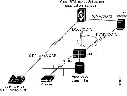
This section describes the implementation of the PacketCable Multimedia (PCMM) feature that provides quality of service (QoS) for type 1 clients managed by the Cisco BTS 10200 Softswitch. This feature is applicable to endpoints using SIP, MGCP, or H.323 as the call signaling protocol.
Note
Figure 4 provides a sample system context for this feature.
Figure 4 Network Architecture with Policy Server and PCMM Interfaces
As shown in Figure 4, the PCMM implementation requires the Cisco BTS 10200 Softswitch to communicate with a policy server (PS), which is a third party device. For calls originating on, or terminating to a type 1 client, the Cisco BTS 10200 Softswitch acts as an application manager (AM) and sends requests to the PS for admission control through PCMM-based signaling. The PS in turn requests the CMTS to allocate bandwidth and other resources as in the request. After resources are allocated, the results are provided to the AM (via the PS) and the Cisco BTS 10200 Softswitch continues with call signaling to set up the call.
For the CLI provisioning procedure related to PCMM-based functions, see the "Provisioning PCMM-Based QoS for Type 1 Clients" section.
For maintenance commands related to the CMTS and PS, see the "Reset, Control, and Status Commands" section.
SOAP/XML Interface for CMS Subscriber Provisioning
This section describes the implementation of PacketCable CMS subscriber provisioning on the BTS 10200 with a Simple Object Access Protocol/Extensible Markup Language (SOAP/XML) interface.
This initial release supports only the Pkt-p1 interface to the Provisioning Server (PS)/Call Management Server (CMS) and only the PcspService Object, without extensions. It supports a subset of the call feature objects in the ListOfCallFeatures element.
In the Pkt-p1 interface, the Cisco BTS 10200 Softswitch plays the role of CMS. Any third-party PS using SOAP, Version 1.1, can provision the BTS. The requests and responses between the CMS and the PS are encapsulated in SOAP, Version 1.1, messages. A secure transport protocol is provided by Internet Protocol Security (IPSec).
SOAP/XML Interface
Currently, a user can connect to a BTS 10200 Common Object Request Broker Architecture (CORBA) server to access command templates and enter command executions, allowing system-to-system provisioning. The feature described in this document allows the XML commands to be transported by the SOAP transport protocol, rather than CORBA. Users of this feature communicate with a BTS SOAP server, which resides on the BTS 10200 EMS.
The BTS 10200 XML schema is a general purpose schema currently used by the XML/CORBA interface. The XML schema does not change with the incorporation of the SOAP transport protocol.
SOAP/XML Adapter and specifications are documented in the Cisco BTS10200 Softswitch SOAP Adapter Interface Specification Programmer Guide.
System Components
CMS subscriber provisioning involves the interface between the following components:
•
•
CMS Subscriber Provisioning
CMS subscriber provisioning includes the operations necessary to provide a specified service to a customer and provides two main functions:
•
•
Call Features
The following call features are supported by the PacketCable CMS subscriber provisioning interface. The name of each feature is listed below in PacketCable terminology, followed by the corresponding BTS 10200 feature in ( ):
•
•
•
•
•
•
•
•
•
•
•
•
•
•
•
•
•
•
•
•
•
•
•
Prerequisites for CMS Subscriber Provisioning
•
•
Limitations On CMS Subscriber Provisioning
•
•
•
•
Planning
Delivery of the features and functions described in this document requires interoperability with the network elements connected to the Cisco BTS 10200 Softswitch. See the "Component Interoperability" section in the Cisco BTS 10200 Softswitch Release Notes, which lists the specific peripheral platforms, functions, and software loads that have been tested by Cisco for interoperability with the Cisco BTS 10200 Softswitch.
Note
Installation
Installation of Cisco BTS 10200 Softswitch software follows a standard process. For details, see the Application Installation Procedure in the Cisco BTS 10200 Softswitch documentation set. Of the three main PacketCable feature areas (DQoS, EM, and security), two of them (DQoS and EM) are always installed, and do not require the setting of any special flags during software installation. However, the third area (security) is not installed unless a special flag (IPSEC_ENABLED) is set in the opticall.cfg file during software installation.
Caution
Provisioning Procedures
This section explains how to perform the following procedures:
•
•
•
•
These tasks include examples of CLI commands that illustrate how to provision the specific feature. Most of these tables have additional tokens that are not included in the examples. For a complete list of all CLI tables, tokens, descriptions, valid ranges, and default values, see the Cisco BTS 10200 Softswitch Command Line Interface Reference Guide.
Note
Provisioning Basic PacketCable and DQoS Features
This section describes how to provision the Cisco BTS 10200 Softswitch interfaces to connect to other PacketCable-based NEs and how to select dynamic quality of service (DQoS) options. It includes the following tasks:
•
•
•
•
•
•
Provisioning CMS Parameters
This section describes how to provision DQoS functionality for the CMS logical entity on the Cisco BTS 10200 Softswitch (Call Agent).
SUMMARY STEPS
1.
2.
3.
Note
DETAILED STEPS
Provisioning the CMS Interfaces to the CMTS and eMTA
This section describes how to provision the interfaces to the CMTS and eMTA nodes. Specific tables are provisioned for each of these interfaces:
•
•
–
–
–
SUMMARY STEPS
1.
2.
3.
4.
5.
6.
7.
8.
Note
DETAILED STEPS
Step 1
add aggr id=cmts777;
tsap-addr=ADDRESS123.cisco.com; aggr-profile-id=aggrprofile001Creates the CMTS (aggregation device) and enables DQoS support.
The TSAP-ADDR can be a DNS or IP address. If you enter a DNS address, it must be a fully qualified domain name (FQDN).
Caution
Step 2
add mgw-profile id=mgwprofile777; mgcp-version=MGCP-1-0; mgcp-variant=NCS-1-0; mgcp-default-pkg=LINE; mgcp-conn-id-at-gw-supp=n;
Creates the mgw-profile for this type of eMTA, and specifies values for the optional parameters.
The default values for these parameters might be adequate for your specific case. In each case, you can use the show command to find out how the parameter is currently set. See the Cisco BTS 10200 Softswitch Command Line Interface Reference Guide for parameter definitions and valid ranges.
Step 3
show mgw-profile id=mgwprofile777;
Verify that the following values are present:
vendor=Cisco [or applicable vendor name]
mgcp-version=MGCP-1-0
mgcp-variant=NCS-1-0
mgcp-default-pkg=LINE
codec-neg-supp=y
pc-mptime-supp=y
mgcp-xdlcx-supp=n
domain-name-caching-supp=y
mgcp-conn-id-at-gw-supp=y
Shows the provisioned values for the parameters in the mgw-profile table.
Step 4
change mgw-profile id=mgwprofile777; mgcp-version=MGCP-1-0; mgcp-variant=NCS-1-0;
If any of the mgw-profile token values (from Step 3) need to be changed, use the change mgw-profile command.
Step 5
add mgw id=CiscoGW50; tsap-addr=192.168.26.104; call-agent-id=CA146; mgw-profile-id=mgwprofile777; type=rgw; aggr-id=cmts777; node=main0044;
Creates the MGW ID for a single eMTA, and specifies values for the other required parameters.
Be sure to set TYPE=RGW for an eMTA.
You must enter the value for AGGR-ID to identify the appropriate CMTS for this eMTA.
The node token allows you to identify a hybrid fiber coax (HFC) node to which the eMTA is assigned. Typically, each eMTA is assigned to a node, and one or more nodes are assigned to a CMTS.
Step 6
add termination prefix=aaln/; port-start=1; port-end=2; type=LINE; mgw-id=CiscoGW50;
Creates the line termination for the eMTA and specifies values for the required parameters.
For eMTA terminations, always enter type=LINE.
Step 7
control mgw id=CiscoGW50; target-state=INS; mode=forced;
status mgw id=CiscoGW50;
Brings the eMTA in service (INS state), and verifies that the administrative state is INS.
Step 8
equip subscriber-termination id=sub3456;
control subscriber-termination id=sub3456; target-state=INS; mode=forced;
status subscriber-termination id=sub3456;
Equips the termination, places it in service (INS state), and verifies that the administrative state is INS.
Provisioning DQoS Parameters for Codec Negotiation Service
The Quality of Service (qos) table is used in providing the codec negotiation service. Codec negotiation is the process the Cisco BTS 10200 Softswitch uses to find a common codec for the compression or decompression of a signal between two gateways. The Subscriber Profile (subscriber-profile) and Subscriber (subscriber) tables point to the qos table.
The following commands allow you to specify the required characteristics for these tables.
SUMMARY STEPS
1.
2.
add subscriber-profile; add subscriber.
Note
DETAILED STEPS
Provisioning TGCP Interfaces to TGWs
This section describes how to provision the TGCP interfaces to the TGWs.
The mgw-profile table provides templates for defining each type of TGW by hardware vendor. It identifies the specifications and settings necessary for communications between the Cisco BTS 10200 Softswitch (which functions as the MGC) and each type of TGW. Several tokens in this table have values that can be overwritten after the Cisco BTS 10200 Softswitch (MGC) queries the TGW for supported capabilities. If the TGW returns a value different from the value originally provisioned in the Cisco BTS 10200 Softswitch, the returned value automatically replaces the originally provisioned value.
SUMMARY STEPS
1.
2.
3.
4.
5.
Note
DETAILED STEPS
Step 1
add mgw-profile id=tgwprf222; vendor=cisco; mgw-type=MGX8850; mgcp-version=MGCP-1-0; mgcp-variant=TGCP-1-0; mgcp-default-pkg=TRUNK; pc-mptime-supp=y;
Creates an mgw-profile for this type of TGW and specifies values for required parameters.
Be sure to set the following values for a TGW:
MGCP-VERSION=MGCP-1-0
MGCP-VARIANT=TGCP-1-0
MGCP-DEFAULT-PKG=TRUNK
Note
Step 2
add mgw id=tgw50; tsap-addr=TGW1515.cisco.com; call-agent-id=CA146; mgw-profile-id=tgwprf222; type=tgw;
Links a specific TGW to the applicable mgw-profile.
Note
Step 3
add termination prefix=S0/ds1-2/; mgw-id=tgw50; port-start=1; port-end=24; type=TRUNK;
Creates trunk terminations for the TGW.
Note
Step 4
add qos id=gold-service; lptime=20; hptime=20; codec-type=PCMU; client-type=dqos;
Adds a qos with the preferred codec type, specifies client type as DQoS, and other parameters as needed.
You must enter client-type=dqos in this command (and then assign this qos ID to the trunk-grp in the next step) to enable DQoS functionality for the trunk group.
Caution
Step 5
add trunk-grp id=101; call-agent-id=CA146; tg-type=ss7; qos-id=gold-service; mgcp-pkg-type=IT; pop-id=chicago333;
Assigns a qos ID and pop ID to each TRUNK-GRP.
For trunk groups on TGCP-based TGWs (MGCP-VARIANT=TGCP-1-0 in the mgw-profile table), set the MGCP-PKG-TYPE value to IT (ISUP trunk package).
You must assign the qos ID (the ID of the qos table that was provisioned in the previous step) to the trunk-grp to enable DQoS functionality for the trunk group.
Provisioning the Keepalive AUEP and ICMP Ping Options
This section explains how to provision the keepalive AUEP and ICMP ping options. There are two tokens to provision:
•
•
SUMMARY STEPS
1.
2.
3.
4.
5.
6.
Note
However, if mgw-monitoring-enabled=N, the AUEP and the ICMP ping are globally disabled, and the keepalive-method token is not checked.The token values shown in this section are examples. In addition, these tables have many additional optional tokens not shown in these examples. For a complete list of all the tokens for each table, see the Cisco BTS 10200 Softswitch Command Line Interface Reference Guide.
DETAILED STEPS
Step 1
show call-agent id=CA146;
The system responds with the current settings for the call-agent table. The default value of mgw-monitoring-enabled is Y.
Show the setting for mgw-monitoring-enabled in the call-agent table.
Step 2
change call-agent id=CA146; tsap-addr=CA146.cisco.com; mgw-monitoring-enabled=Y;
If the current value of mgw-monitoring-enabled is N, use this command to change it to Y. (Otherwise, go to Step 3.)
Step 3
show mgw-profile id=mgwprofile001;
The system responds with the current settings for the mgw-profile table.
Show the setting for keepalive-method in the mgw-profile table.
Step 4
change mgw-profile id=mgwprofile001; keepalive-method=<value (see options)>;
change mgw-profile id=mgwprofile001; keepalive-method=auep-icmp;
If necessary, change the value of keepalive-method in the mgw-profile table.
The options for keepalive-method are:
•
•
•
change mgw-profile id=mgwprofile001; mgcp-keepalive-interval=120; mgcp-keepalive-retries=4; mgcp-max-keepalive-interval=720; mgcp-max1-retries=3; mgcp-max2-retries=4;
If necessary, change the value of other keepalive tokens in the mgw-profile table.
The mgcp-max1-retries and mgcp-max2-retries tokens can be adjusted, if necessary, to improve response if there are network bandwidth or reliability issues, or if an MGW is slow in responding to commands from the CA. For a detailed explanation of how these and other parameters affect the keepalive process, see Appendix C of the Cisco BTS 10200 Softswitch Troubleshooting Guide.
Step 6
add mgw id=mgw_abc; mgw-profile-id=mgwprofile001;
Links an individual MGW (eMTA) to an mgw-profile.
Provisioning MGCP Command Timeout and QoS Parameters
This section describes the steps required to provision the parameters for MGCP command timeout, silence suppression, and echo cancellation.
•
•
Step 1
show ca-config
type=mgcp-t-max;show ca-config type=mgcp-t-hist;
Display the values of MGCP-T-MAX and MGCP-T-HIST.
Parameter Descriptions:•
•
Note
TipStep 2
change ca-config type=mgcp-t-max; datatype=integer; value=24;
change ca-config type=mgcp-t-hist; datatype=integer; value=36;
If necessary, change the values of MGCP-T-MAX and MGCP-T-HIST.
Caution
Note
Step 3
show mgw-profile id=telcomta;
Display the values of EC-SUPP in the mgw-profile table.
Parameter Description:EC-SUPP—Specifies whether the MGW supports echo cancellation. Values are:
•
•
Note
Step 4
change mgw-profile id=telcomta; ec-supp=y;
If necessary, change the value of EC-SUPP in the mgw-profile table.
Step 5
show qos id=mta-subscriber;
Display the values of SILENCE-SUPPRESSION and ECHO-CANCELLATION in the qos table.
Parameter Descriptions:•
–
–
–
•
–
–
–
Note
Step 6
change qos id=mta-subscriber;
silence-suppression=on; echo-cancellation=off;
If necessary, change the values of SILENCE-SUPPRESSION and ECHO-CANCELLATION in the qos table.
Provisioning the Aggregation ID Subnet
Establishing subnets for MTAs enables a service provider to use the Subnet table to statically configure all subnets handled by every Cable Modem Termination System (CMTS). The Cisco BTS 10200 Softswitch uses the IP address of the embedded Multimedia Terminal Adapter (eMTA) and Subnet table to determine the CMTS handling of a particular eMTA. An eMTA is a residential gateway. A CMTS is an aggregation device for multiple eMTAs.
An effective aggr-id is the aggr-id in effect for a particular eMTA. It identifies the CMTS to which the Cisco BTS 10200 Softswitch sends Dynamic Quality of Service (DQoS) requests for that eMTA. A manual aggr-id is an aggr-id that is provisioned by a service provider. If an aggr-id is provisioned in the Media Gateway table or Subnet table, it is a manual aggr-id.
The Cisco BTS 10200 Softswitch uses the following data precedence to decide an MTAs aggr-id:
•
•
This section explains the steps to manually provision subnets for an MTA.
Provision the Media Gateway
This section explains the steps required to provision the residential (media) gateway (eMTA), if it has not already been provisioned. Provisioning an aggr-id for each eMTA is no longer required.
SUMMARY STEPS
1.
2.
3.
4.
DETAILED STEPS
Provision the Subnet
This section explains the steps required to provision a subnet and associate it to an aggregation id. The aggr-id identifies the CMTS on the subnet level. The Cisco BTS 10200 Softswitch determines which subnet an eMTA belongs to by looking at the eMTAs IP address and the subnet's IP prefix. For example, if the eMTAs IP address is 192.168.0.1, then it is on subnet (prefix=192.168.0.0, prefix-length=24). If eMTA is on a provisioned subnet, the provisioned subnet aggr-id is the effective aggr-id for the eMTA.
SUMMARY STEPS
1.
2.
3.
DETAILED STEPS
Missing Provisioned Data
A CMTS (AGGR) is provisioned in the Aggregation table, but none of the provisioned Subnets refers to that CMTS (AGGR).
Use the following command to audit condition:
report aggr subnet=NONE;Provisioning CMTS Discovery Using the Static Subnet Table
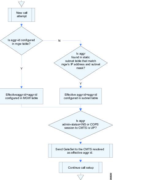
To enable CMTS Discovery Using the Static Subnet table, you statically provision the Subnet table in the BTS 10200 system. A service providers must configure all subnets handled by every CMTS using the Subnet table. The BTS 10200 uses the IP address of the multimedia terminal adapter (MTA) and the Subnet table information to determine the CMTS (AGGR) handling the MTA. Figure 5 provides a network diagram of the BTS 10200 to CMTS network connectivity. Figure 6 provides the CMTS to MTA association preference flow.
Figure 5 Network Diagram
Figure 6 CMTS to MTA Association Preference
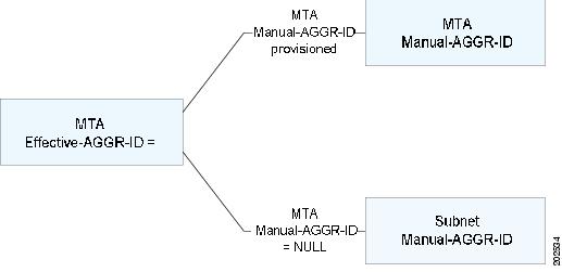
The BTS 10200 uses the following data precedence to decide MTA Effective-AGGR-ID as shown in Figure 7:
•
•
Figure 7 MTA Effective-AGGR-ID Data Precedence
Provisioning a Subnet
This section explains the steps required to provision a subnet.
SUMMARY STEPS
1.
2.
3.
4.
DETAILED STEPS
Provisioning an AGGR-ID
This section explains the steps required to provision an AGGR-ID.
SUMMARY STEPS
1.
2.
DETAILED STEPS
Provisioning the Display of Non DQoS Calls
This section explains the steps required to provision the display of non DQoS calls.
The CLI commands for displaying non DQoS calls are part of the Release 5.0 MR2 enhancement to the CMTS Discovery Using the Static Subnet table.
SUMMARY STEPS
1.
2.
DETAILED STEPS
Provisioning the Refreshing of IP Address Cache
This section explains the steps required to provision the refreshing of IP address cache. The CLI commands for refreshing IP address cache CLI commands are part of the Release 5.0 MR2 enhancement to the CMTS Discovery Using the Static Subnet Table feature.
SUMMARY STEPS
1.
2.
DETAILED STEPS
Termination Connection Test with the DQoS Diagnostic Command
This section explains the steps required to provision a termination connection test with the DQoS diagnostic commands.
Establishing a termination connection test with the DQoS diagnostic commands are part of the Release 5.0 MR2 enhancement to CMTS Discovery Using the Static Subnet table feature.
SUMMARY STEPS
1.
DETAILED STEPS
Provisioning Subscriber ID Parameters and DQoS Measurement Counter
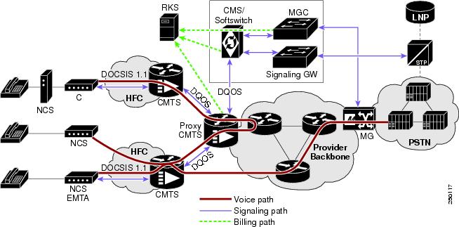
Packet Cable ECN, DQoS 1.5-N-06.0339-4 was written as part of the Packet Cable 1.5 specification to add Subscriber ID to all Gate Control messages and enhance error codes returned from the CMTS (Cable Modem Termination System).
In the current DQoS specification, the Gate ID is unique only to individual CMTS systems. With the CMTS proxying all CMS (Call Management Server) Gate control messaging through a central device which manages the CMTS connections on the behalf of the CMS, the CMS only has a single COPS (Common Open Policy Service) association to the proxy device. Due to the fact that Gate IDs can be duplicated when using multiple CMTS systems, the ECN defines adding a Subscriber ID to each Gate Control message to disambiguate the Gate IDs between the CMS and proxy device. This particular application is shown in Figure 8:
The ECN DQoS 1.5-N-06.0339-4 augments the following COPS messages, where the Subscriber ID parameter is added:
•
•
•
•
The Subscriber ID is available at the CMS and is used in the Gate-Set messages.
This ECN also enhances the error codes returned from CMTS or its proxy to allow more precise definition why a particular gate operation may have failed.
Implementation of the above specified ECN is part of this feature. Additionally, some new measurement counters for COPS are added.
Figure 8 Network Diagram
CLI Provisioning and Schema
CLI needs to support the following schema change.
For complete CLI information, see the Cisco BTS 10200 Softswitch Command Line Interface Reference Guide.
AGGR PROFILE TABLE
The AGGR-PROFILE Table is used to define properties of an Aggregation Device, CMTS or PCMM Server.
Table Name: AGGR-PROFILE
Table Containment Area: Call Agent
Command Types
add, audit, change, delete, help, show, sync
Examples
add aggr-profile id=er1; subscriber-id-supp=y;change aggr-profile id=er1; subscriber-id-supp=n;Usage Guidelines
Primary Key Token(s): id
POP TABLE
Table Name: POP
Table Containment Area: Call Agent, POTS Feature Server, AIN Feature Server
Command Types
add, audit, change, delete, help, show, sync
Examples
add pop id=dallaspop; state=tx; country=usa; aggr-id=proxycmts;Usage Guidelines
Primary Key Token(s): id
Delete Rules: Foreign key constraints
•
•
To support this feature, COPS measurement counters and additional DQoS counters were added. For more details, refer to Cisco BTS 10200 Softswitch Operations and Maintenance Guide.
Provisioning Security Interfaces
This section describes the PacketCable-based security interface feature and explains how to provision security options. The subsections are as follows:
•
•
•
•
•
•
Note
Provisioning Parameters for Secured Media
This section describes how to provision the SECURED-MEDIA-ONLY flag, which affects transmission of security parameters from the qos and ciphersuite tables when the system sets up a call. This parameter affects the setup of calls to unsecured MGWs.
SUMMARY STEPS
1.
2.
DETAILED STEPS
Provisioning Security Interfaces to the MTA
The MTA is the only device that uses Kerberos key management. This section explains how to provision the MTA IP security (IPsec) interface, including:
•
•
•
Note
Cisco BTS 10200 Softswitch Command Line Interface Reference Guide.
SUMMARY STEPS
1.
2.
3.
4.
DETAILED STEPS
Provisioning Security Interfaces to the CMTS
This section explains how to provision security interfaces to the CMTS.
SUMMARY STEPS
1.
2.
3.
Note
DETAILED STEPS
Provisioning Security Interfaces to the TGW
This section explains how to provision security interfaces to the TGW.
SUMMARY STEPS
1.
2.
3.
Note
DETAILED STEPS
Provisioning Security Interfaces to the RKS
This section explains how to provision security interfaces to the RKS.
SUMMARY STEPS
1.
2.
3.
Note
DETAILED STEPS
Provisioning IPsec Security Associations and Ciphersuite Algorithms
This section explains how to provision the IPsec security associations (SAs) and the ciphersuite encryption and authentication algorithms.
•
•
SUMMARY STEPS
1.
2.
3.
Note
DETAILED STEPS
Provisioning Event Messages
This section explains how to provision EM functionality on the Cisco BTS 10200 Softswitch. It includes the following tasks:
•
•
•
Provisioning Support for EM Transmission and Storage
The commands in the following procedure specify the required IDs for the primary and secondary RKSs and link them with the Call Agent (CMS/MGC). They also control parameters related to the transmission of EMs to the RKS and parameters related to storage of EMs on the CA.
•
•
SUMMARY STEPS
1.
2.
3.
4.
5.
DETAILED STEPS
The token values shown in this section are examples. These tables have many additional optional tokens not shown in these examples. For a complete list of all the tokens for each table, see the Cisco BTS 10200 Softswitch Command Line Interface Reference Guide.
DETAILED STEPS
Step 1
add radius-profile id=prirks; tsap-addr=192.168.100.100; encryption-key=abcdef1234567890; acc-rsp-timer=7; acc-req-retransmit=4; description=primary_billing_server
add radius-profile id=secrks; tsap-addr=192.168.100.101; encryption-key=abcdef1234567890; acc-rsp-timer=6; acc-req-retransmit=2; description=secondary_billing_server
Creates the interfaces to the primary and secondary RKS units and sets values for various parameters.
The ACC-RSP-TIMER and ACC-REQ-RETRANSMIT tokens control the retransmission of EMs from the CA to the RKSs when the first attempt does not go through. ACC-RSP-TIMER controls how long the system waits before retransmitting, and ACC-REQ-RETRANSMIT controls how many retransmission attempts are made to the target RKS.
Step 2
change ca-config type=retry-pri-rks-timer; datatype=integer; value=14;
change ca-config type=em-file-open-time; datatype=integer; value=900;
change ca-config type=em-file-size; datatype=integer; value=50;
Specifies how the system stores EMs in files on the CA (when loss of communication with the RKSs prevents EMs from being transmitted to the RKSs).
An open EM file does not close automatically when communication to the RKS is restored. The file closes automatically according to the provisioned value in EM-FILE-OPEN-TIME or EM-FILE-SIZE, whichever occurs first.
The command is shown as change ca-config. However, if the system responds that the parameter does not exist, reenter the command as add ca-config.
Step 3
change ca-config type=batch-mode-supp; value=Y;
change ca-config type=batch-latency; value=240;
Provisions batch mode handling of EMs.
The command is shown as change ca-config. However, if the system responds that the parameter does not exist, reenter the command as add ca-config.
Step 4
change ca-config type=RADIUS-DSCP-TOS; value=96;
Sets the DSCP for signaling packets on RADIUS interfaces between the CMS and RKS.
The default values for this parameter might be adequate for your specific case. We do not recommend that you change this value unless necessary, and recommend that you contact Cisco TAC regarding any plans to change it.
The command is shown as change ca-config. However, if the system responds that the parameter does not exist, reenter the command as add ca-config.
Step 5
change ca-config type=EM-PRIVACY-IND-SUPP; datatype=BOOLEAN; value=Y;
Instructs the system to include the privacy-indicator field in the signaling start EM. For details of this field, see the "EM Generation Details and Content" section.
This change takes effect immediately when provisioned. It is not necessary to restart any platforms.
The command is shown as change ca-config. However, if the system responds that the parameter does not exist, reenter the command as add ca-config.
Provisioning the System to Generate EMs for Billing
The Cisco BTS 10200 Softswitch can provision billing support using either call detail blocks (CDBs), which are assembled into call detail records (CDRs) by an external billing server, or PacketCable EMs, which are transferred to an external RKS that assembles CDRs from the EMs.
The Cisco BTS 10200 Softswitch contains two PacketCable-based logical network elements, the CMS and MGC. The CMS and MGC have provisionable element IDs as described in this section. The applicable element ID is included in each EM sent from the CMS or MGC.
To provision the Cisco BTS 10200 Softswitch to generate EMs for billing, complete the steps shown in the following section.
SUMMARY STEPS
1.
2.
3.
4.
DETAILED STEPS
The token values shown in this section are examples. In addition, these tables have many additional optional tokens not shown in these examples. For a complete list of all the tokens for each table, see the Cisco BTS 10200 Softswitch Command Line Interface Reference Guide.
DETAILED STEPS
Step 1
show call-agent-profile id=CA146;
Displays the current parameters for the CA profile.
Step 2
change call-agent-profile id=CA146; cdb-billing-supp=N; em-billing-supp=Y; pri-rks-profile-id=prirks; sec-rks-profile-id=secrks;
add call-agent-profile id=CA146; cdb-billing-supp=N; em-billing-supp=Y; pri-rks-profile-id=prirks88; sec-rks-profile-id=secrks88;
If the system response (in the display from Step 1) contains data, use the change call-agent-profile command if you want to change any of the parameter values.
If the system response (in the display from Step 1) indicates that this table does not exist, then you must create it using the add call-agent-profile command. Otherwise, the EM function is not supported and EMs are not generated.
Caution
EM and CDB Billing OptionsIn a PacketCable network, the service provider can choose EM-based billing or CDB-based billing.
Caution
Note
Note
RKS IDsThe value for pri-rks-profile-id (primary RKS profile ID) must be the same as the value for the radius-profile ID for the primary RKS, and the value for sec-rks-profile-id (secondary RKS profile ID) must be the same as the radius-profile ID for the value for the secondary RKS.
Step 3
change call-agent-profile id=CA146; cms-id=12345; mgc-id=67890; feid=feid0001;
Identifies the CMS and MGC logical network elements and the financial entity ID (FEID). The system uses these IDs when generating EMs.
The Cisco BTS 10200 Softswitch contains both the CMS and MGC logical entities. For PacketCable systems, the CMS-ID must be entered. If your Cisco BTS 10200 Softswitch communicates with a TGW, you must enter the MGC-ID. The FEID value is also required for EM billing.
You must provision the CMS-ID and MGC-ID tokens so that the Cisco BTS 10200 Softswitch can provide support for the Communication Assistance for Law Enforcement Act (CALEA). For provisioning procedures related to CALEA support, see the Cisco BTS 10200 Softswitch Provisioning Guide.
Step 4
change subscriber id=SUB5551212; sub-profile-id=profile777; account-id=123456789; billing-type=FR2;
(Optional) Provision a billing type (flat rate or measured rate) and an account ID for individual subscribers.
Provisioning Media_Alive Verification for EMs
Use the Activity (activity) table to schedule and configure Media_Alive EMs. These EMs are used during longer-duration calls to verify that the media connection is still alive. For information on these operational commands, see the "Viewing Media_Alive Verification for EMs" section.
For an additional sample provisioning sequence, see the Cisco BTS 10200 Softswitch Provisioning Guide. For additional reference information on CLI tables and parameters, see the Cisco BTS 10200 Softswitch Command Line Interface Guide.
Provisioning PCMM-Based QoS for Type 1 Clients
The PCMM-based QoS capability includes the following CLI database changes beginning with Release 5.0:
•
•
•
The BTS 10200 uses the AGGR table for maintaining a COPS connection with the PS. The POLICY-SERVER table, which is an alias to the AGGR table, is provided to distinguish between the CMTS-type of COPS client and the PS-type of COPS client.
Tip
Office Provisioning—Configure PCMM Support, Policy Server, and QoS
Step 1
change call-agent-profile id=CA146; pcmm-supp=Y;Step 2
add aggr-profile id=ps-profile; <additional parameters as needed>;Step 3
add policy-server id=ps-dallas; tsap-addr=ps@dallas.cisco.com
Note
Step 4
change pop id=pop-dallas; policy-server-id=ps-dallas;Step 5
change qos id=qos-pcmm; client-type=mm-cops;
Configuring Subscribers and Trunk Groups to Use PCMM-Based Admission Control
Step 1
change subscriber-profile id=sub-1; qos-id=qos-pcmm;or
change subscriber id=sub-1; qos-id=qos-pcmm;Step 2
change trunk-grp id=99; qos-id=qos-pcmm;
CA Configuration and Aggr Profile Parameters
Table 1 lists the parameters that have been moved from the ca-config table to the aggr-profile table in Release 5.0.
Additionally, the new timer gate-committed-recovery-timer was added to the AGGR-PROFILE table, and the new configuration parameter BEST_EFFORT_ON_QOS_FAIL was added to the ca-config table.
Status, Control, and Reset Commands
For maintenance commands related to the CMTS and PS, see the "Reset, Control, and Status Commands" section.
Provisioning AuditConnection Parameters
The system uses the AuditConnection command to audit the status of connections to any MGCP-based endpoint. This allows the system to discover call identifiers corresponding to stray connections, that is, connections which exist on an MGCP endpoint but are not accounted for on the Cisco BTS 10200 Softswitch. An example of a stray connection is a ringing endpoint for which no call is being set up. These stray connections can occur, for example, on endpoints that were engaged in a three-way call (TWC) during a CA failover. The system can send an AuditConnection command to recover the connection state from the MGCP device after a CA failover. A provisionable parameter in the Cisco BTS 10200 Softswitch database allows the service provider to enable or disable the AuditConnection functionality for each MGW profile. The system uses the MGCP-compliant DeleteConnection command to clear stray connections.
This section describes the steps required to provision the AuditConnection functionality for each MGW profile.
Note
SUMMARY STEPS
1.
2.
DETAILED STEPS
Operations, Billing, and EM Transfer Procedures
This section covers the operational features of the Cisco BTS 10200 Softswitch PacketCable implementation, including the following topics:
•
•
•
•
PacketCable Billing Data and Formats in Deployments Using CDBs
For deployments that use CDBs for billing (rather than EMs), the following CMTS and eMTA identifying information is included in the CDBs:
•
•
•
•
•
•
•
•
•
See the Appendix A of the Cisco BTS 10200 Softswitch Billing Guide for a complete list of billing fields and field contents, and a description of the options for CDB file-naming conventions.
Reset, Control, and Status Commands
This section describes the reset, control, and status commands for aggr and policy-server.
Reset
To provide the functionality of resetting the TCP connections to the CMTS and PS, the BTS 10200 implements a reset command for the AGGR (CMTS) or PS. The system closes and reinitiates the TCP connection and COPS session to the CMTS or PS when the operator executes the following CLI command:
reset aggr id=CMTS1;reset policy-server id=PS-DALLAS;If an AGGR or POLICY-SERVER is in any operational state other than in service (INS), for example if the AGGR or POLICY-SERVER is operationally out of service (OOS) or transitioning between operational states, the system does not execute the reset. It responds to the reset command by displaying a failure message.
Control
The system implements control command for the AGGR. There are only two possible administrative states for AGGR (CMTS/PS) IN-SERVICE and OUT-OF-SERVICE.
For control out-of-service with mode set to forced/graceful, the Cisco BTS 10200 Softswitch closes the TCP connection (thus COPS session) to CMTS or PS when operator takes the AGGR out-of-service by executing the following CLI command. After you control the aggr or policy-server OOS, the BTS 10200 does not attempt to set up any new calls through this aggr or policy-server. Existing calls may or may not be affected depending upon the CMTS implementation.
control aggr id=CMTS1; target-state=OOS; mode=forced;control policy-server id=PS-DALLAS; target-state=OOS; mode=forced;The system initiates a set up for TCP as well as a COPS connection to the CMTS or the PS when the operator brings the AGGR into in-service mode by executing the following CLI command:
control aggr id=CMTS1; target-state=INS; mode=forced;control policy-server id=PS-DALLAS; target-state=INS; mode=forced;Status
The system shows the operational state when the operator queries the current status of TCP and COPS connection associated with the CMTS or PS:
status aggr id=CMTS1;status policy-server id=PS-DALLAS;Example:status aggr ID=c7246-777;
ID -> c7246-777
OPER STATE -> AGGR IN Service
RESULT -> ADM configure result in success
REASON -> ADM executed successfullyFor the STATUS AGGR command, the available displayed values include INS (in service), OOS (out of service), and CONNECTING. CONNECTING state means that the Cisco BTS 10200 Softswitch is reattempting to connect to the CMTS.
For a DQoS/PCMM subscriber, Cisco BTS 10200 first checks whether AGGR_ID is provisioned in the MGW table. If it's not provisioned in the MGW table, BTS 10200 looks for the AGGR_ID value provisioned in the SUBNET table (that is, the AGGR_ID value is resolved using the value provisioned in the SUBNET table).
If the AGGR_ID is provisioned (resolved), BTS 10200 checks the status of AGGR or POLICY_SERVER table. For a DQoS/PCMM call, if the AGGR or POLICY_SERVER operational state is not INS, and the BEST_EFFORT_ON_QOS_FAIL flag is set to N, the system drops the call. If the AGGR or POLICY_SERVER operational state is not INS, and the BEST_EFFORT_ON_QOS_FAIL flag is set to Y, the system continues the (DQoS/PCMM) call on a best-effort basis.
If the AGGR_ID is not provisioned in the MGW or SUBNET table, BTS 10200 lets the call to continue on a best-effort basis.
Note
Manual Recovery and Transfer of Stored EMs
This section describes how to manually recover and transfer stored EM files from the CA to the RKS. This procedure must be used if communication to both RKS units goes down. Perform these procedures after communication is restored.
Recovering the Billing Files
Note
Billing data is normally transferred to the RKS on a real-time basis. In the unlikely event that communications with the RKS go down, alarms are raised and billing data files are written to a local drive on the Cisco BTS 10200 Softswitch (see the /opt/BTSem directory on the Call Agent (CA) that generated the EMs). If communications are not promptly restored, additional billing alarms of increasing severity are raised at time intervals of 1 hour (minor), 3 hours (major), and 5 hours (critical).
EMs that are not successfully transferred to the RKS are stored on the Call Agent. The system uses the naming conventions specified in PacketCable ECN EM-N-04.0186-3 for the stored EMs. Here is the format for the file name:
PKT_EM_<yyyymmddhhmmss>_<priority>_<record type>_<node id>_<sequence>.bin
The parameters are defined as follows:
•
•
–
–
–
–
–
•
•
•
•
•
Here is an example of a typical EM file name:
PKT_EM_20050915103142_3_0_01234_000002.bin
All billing data generated during the period of the communication outage is stored in the /opt/BTSem directory. If communication with the RKS is lost for an extended period, the available disk space on the local Softswitch drives can begin to fill up with EM files. The system monitors the amount of space available on the disks and raises alarms of increasing severity when the disks are 50 percent (minor), 70 percent (major) and 100 percent (critical) full.
Note
We recommend that you monitor the available disk space on a regular basis to prevent the possible loss of billing data. If the disks become full, the data on the disk is preserved and new EMs are discarded.
Caution
Sending Billing Files to the RKS via FTP
To send billing files from the CA to the RKS, perform the following steps:
Step 1
cd /opt/BTSem
Step 2
ftp <RKS name>
Step 3
Step 4
bin
Step 5
cd /.../.../<billing file subdirectory name>
Step 6
put <billing-filenames>
Step 7
bye
Comparing Checksums
To compare the checksums to ensure that the data was transferred correctly, perform the following steps:
Step 1
Step 2
cd /.../.../<billing file subdirectory name>
Step 3
ls -lrt
Step 4
cksum <billing-filename>
Step 5
a.
b.
If the cksum values are still different, contact Cisco TAC for assistance.
Content of EMs Sent to the RKS
Following is an example of a typical EM sent by the Cisco BTS 10200 Softswitch to an RKS. The format of the event-time field is yyyymmddhhmmss.mmm, where .mmm refers to milliseconds.
EM-Header (1):version: 4 bci: 3378049121- 55555-58 (STD, -06:00:00) event-type: Signaling Start (1) element-type: CMS (1) element-id: 55555 zone: STD, -06:00:00 sequence-number: 618 event-time: 20070117125847.132 status: 0 priority: 128 attribute-count: 6 event-object: 1 Direction-Indicator (37): Originating (1)Viewing Media_Alive Verification for EMs
Use the activity table to schedule and configure Media_Alive EMs. These EMs are used during longer-duration calls to verify that the media connection is still alive.
Step 1
add activity id=MEDIA-ALIVE-EM; freq=6H; start-time=HH:MM;where:
•
Note
•
•
Note
Step 2
show activity id=MEDIA-ALIVE-EM;Sample command line output:
ID=MEDIA-ALIVE-EM
FREQ=30 MINUTES
DAY_OF_MONTH=NA
DAY_OF_WEEK=NA
START_TIME=00:00
FIXED_TIME_INTERVAL=N
ENABLED=N
SO_ENABLED=N
RESTART_ENABLED=N
LAST_CHANGED=2004-10-20 16:45:30
Measurements
Several traffic measurements pertain to the PacketCable implementation. For detailed descriptions see the Traffic Measurements section in the Cisco BTS 10200 Softswitch Operations and Maintenance Guide.
Creating Reports and Displays of Measurements
This section outlines the procedure for creating reports and displays of measurements. It uses the DQoS feature as an example. Additional details about measurement provisioning, reporting, and display commands for all features can be found in the Cisco BTS 10200 Softswitch Operations Guide and the Cisco BTS 10200 Softswitch Command Line Interface Reference Guide.
To create a report file of the DQoS counters for all time intervals in the period starting and ending at specific times, enter the following command. The system prepends the file with the string "Tm_" and writes the file to the /opt/ems/report directory on the active EMS.
report measurement-dqos-summary; start-time=[start-time]; end-time=[end-time]; aggr-id=[ID
of the aggregation router (CMTS) for which data should be reported]; output=[desired file
name for the report]; output-type=[CSV | XML];
where:
start-time and end-time have the format yyyy-mm-dd hh:mm:ss
CSV = comma-separated value
Note
Use any of the following commands to display DQoS counters on your monitor.
•
report measurement-dqos-summary; interval=ALL;•
report measurement-dqos-summary; start-time=[start-time];(start-time has a format of yyyy-mm-dd hh:mm:ss, and the end-time defaults to the most recent interval)•
report measurement-dqos-summary;(start-time and end-time both default to the most recent interval)In this example, the system displays the most recent time interval for all aggregation IDs:
report measurement-dqos-summaryReply: Request was successful.TIMESTAMP 20020310184428DQOS_GATESET_ATTMP 10DQOS_GATESET_SUCC 9DQOS_GATE_COMMIT 9In this example, the display token is used to specify desired counters (separated by commas):
report measurement-dqos-summary; display=DQOS_GATESET_ATTMP,DQOS_GATE_COMMIT;Reply: Request was successful.TIMESTAMP 20020310184428DQOS_GATESET_ATTMP 10DQOS_GATE_COMMIT 9To manage the collection of DQoS measurements, use the following commands:
•
show measurement-prov type=DQOS;•
change measurement-prov type=dqos; enable=yes; time-interval=30;Measurements for the DQoS Feature on COPS Interface
The system supports a number of measurements related to gate coordination over DQoS and PCMM interfaces. See the complete list of measurements in the "Traffic Measurements" chapter of the Cisco BTS 10200 Softswitch Operations and Maintenance Guide.
The Cisco BTS 10200 Softswitch tracks and reports measurements separately for each of the CMTS units (aggregation routers) and PS units it supports.
Measurements for the EM Feature
The system supports a number of measurements related to EMs. Use the following CLI command to retrieve these measurements:
report measurement-em-summaryA typical command and system response are shown below:
See the complete list of measurements in the "Traffic Measurements" chapter of the Cisco BTS 10200 Softswitch Operations and Maintenance Guide.
Events and Alarms
This section lists the events and alarms applicable to the PacketCable implementation, including:
•
•
•
This section lists only the events and alarms that are specific to the PacketCable-based implementation, and includes only the name and description of each alarm. The lists in this section are not exhaustive.
Detailed descriptions of all events and alarms, and recommended corrective actions, are presented in the Cisco BTS 10200 Softswitch Troubleshooting Guide.Events and Alarms Specific to PacketCable-Based Network Elements and PCMM Features
The following events and alarms can be generated in response to processing problems or network connection issues with PacketCable-based network elements:
•
•
•
•
•
Events and Alarms for the EM Feature
The following events and alarms can be generated by the EM feature.
•
•
•
•
•
•
•
•
•
•
•
•
•
•
Events and Alarms for the Security Interface Feature
The following events and alarms can be generated in response to PacketCable-related security signaling conditions:
•
•
•
EM Generation Details and Content
This section describes the internal processes for EM generation and the content of the EMs. These processes are based on the PacketCable Event Message Specification PKT-SP-EM-I10-040721.
Note
EM Generation Details
Table 2 lists the EMs generated by call configuration.
Table 3 lists the EMs that can be generated by the CMS and MGC.
Table 4 lists the EMs for a call and the triggers that generate them (single zone scenario only) in the appropriate logical entities running in the Cisco BTS 10200 Softswitch (CMS and MGC).
Table 5 lists the PacketCable 1.0 features, the EMs generated for them, and the event that triggers the message. Some of the triggering events include the logical entities—Originating CMS (O-CMS) and Terminating CMS (T-CMS)—running in the Cisco BTS 10200 Softswitch.
Table 5 PacketCable 1.0 Features and Associated EMs
911 service—Similar to on-net to off-net call on a unique trunk group ID.
None
—
—
Other N11 services—Similar to above
None
—
—
Database Query
a.
on special trunkNone
—
—
b.
db_query
O-CMS on receipt of response to database dip.
Query types:
1 = Toll-free number lookup
2 = Local number portability (LNP) number lookup
3 = Calling name delivery lookup
If the query is successful—that is, if the query returns the calling party's name—the query type (1, 2, or 3) is included in the EM:
•
•
If the query fails, no EM is sent.
Operator Service
a.
None
Called party number 0 is replaced by Operator Service Provider number.
Only call routing.
b.
Only call routing.
Call block service (with new call to announcement server)
Service instance
O-CMS and T-CMS decide to block call.
If announcement server is connected, event messages are generated for call with same BCID.
Call waiting
a.
Service instance
O-CMS and T-CMS when call waiting is initiated. Second call BCID for service instance.
Only two calls, one active and one on hold, are required. Each half-call generates an EM. A half-call for an on-net announcement server for call waiting tone need not generate an EM. Here is an example of a call scenario:
A calls B, C calls A:
(A -> B, C -> A)
BCID1 for A(O), other leg BCID2
BCID2 for B(T), other leg BCID1
BCID3 for C(O), other leg BCID4
BCID4 for A(T), other leg BCID3BCID4 for CW service instance, related BCID = BCID1
b.
Not supported
—
—
Call forwarding
Service instance
CMS (O/T) when forwarded call leg is initiated.
A calls B, B forwards to C:
(A -> B -> C)
BCID1 for A(O), other leg BCID2
BCID2 for B(T), other leg BCID1
BCID3 for B(O), other leg BCID4
BCID4 for C(T), other leg BCID3
BCID3 for CFW service instance, related BCID=BCID2Return call
(with caller ID privacy restriction)a.
Service instance
O-CMS on feature initiation.
Note
b.
Not supported
—
Repeat call (*66)
CMS-CMS signaling is not supported in this release.
a.
Service instance
Repeat call is initiated.
Separate BCID for service instance.
b.
Not supported
—
—
Voice mail (voice mail server on off-net)
None
—
—
Deposit and retrieval: similar to on-net to off-net call
None
—
—
Message waiting indicator
None
—
No event messages for message waiting.
Privacy indicator
Signaling start
—
Indicates whether the system populates field 12 of the EM with the calling party service (privacy setting) for the calling party.
This attribute uses the previously undefined field 12 in PKT-SP-EM-I10-040721.
See the "EM Content" section for additional requirements.
1 "O" = Name is out of area, unknown, or not available. "P" = Name presentation is restricted.
EM Content
The following EMs for a call contain the attributes listed, and are based on the four logical entities running in the Cisco BTS 10200 Softswitch: Originating CMS (O-CMS), Terminating CMS (T-CMS), Originating MGC (O-MGC), and Terminating MGC (T-MGC).
Direction indicator
X
X
X
X
MTA endpoint name
Originating
Terminating
Name of endpoint (EP) in MGW
Name of endpoint (EP) in MGW
Calling party number
X
X
X
X
Calling party service 1
X
X
X
X
Called party number
X
X
X
X
Routing number
X
X
X
X
Location routing number (LRN)
X
X
X
X
Carrier identification code (CIC)
X
X
Trunk group ID
X
X
Jurisdiction information parameter (JIP)
X
X
X
Ported-in calling number
X
Ported-in called number
X
Calling party NP source
X
Called party NP source
X
Billing type (measured rate or flat rate)
X
Routing number
X
X
CIC
X
X
Trunk group ID
X
X
CIC
X
X
Trunk group ID
X
X
Call termination cause
X
X
X
X
Note
(Off-net to On-net Call)
(On-net to Off-net Call)
Service name (plus specified attributes in the following table)
X
X
Charge number
X
X
X
X
Calling party number
X
X
X
X
Forwarded number
X
(Off-net to On-net Call)
(On-net to Off-net Call)
Service name (plus specified attributes in the table below)
X
X
Charge number
X
X
X
Calling party number
X
X
X
(Off-net to On-net Call)
(On-net to Off-net Call)Database ID
X
X
Query type
X
X
Called party number
X
X
Returned number
X
X
(Off-net to On-net Call)
(On-net to Off-net Call)Media alive
X
X
X
X
(Off-net to On-net Call)
(On-net to Off-net Call)Time adjustment
X
X
X
X
References
Industry Standards
Note