Feedback
Table Of Contents
Getting to Know the Cisco Digital Media Encoder 1100
Simple Guide to Streaming Audio and Video Types
Basic Operation: Using the Front Panel
Connecting an External Storage Device
Exporting Captured Video Files
Factory-Defined Login Credentials
Changing Factory-Defined Login Credentials
Other Required Password Maintenance (Only When Autologon Is Configured)
Tasks to Complete After Changing DME Login Passwords
After a Live Event Is Finished, Remove Its Encoded Video Files from the DME File Share
Advanced Operation: Using the Niagara SCX Web Interface
Configuring the EZStream Buttons
Real Encoder Properties (Helix)
Windows Media Encoder Properties
Windows Media Encoder Settings
My Cisco Digital Media Encoder 1100
Cisco Digital Media Encoder 1100 Properties
Changing the Login Password from the Factory Default
Restoring the Login Password to the Factory Default
Cisco Digital Media Encoder 1100 Alerts
Getting to Know the Cisco Digital Media Encoder 1100
Revised: October 20, 2009, OL-17939-01This chapter includes the following sections:
•
Basic Operation: Using the Front Panel
•
•
•
•
Introduction
This section includes the following topics:
•
What is Streaming Media?
Streaming media is media that is consumed (read, heard, viewed) while it is being delivered. Streaming is more a property of the delivery system than the media itself. The distinction is usually applied to media that is distributed over computer networks; most other delivery systems are either inherently streaming (radio, television, Internet TV) or inherently non-streaming (books, video cassettes, audio CDs).
Cisco Digital Media Encoder 1100 is designed specifically for streaming audio and video media over an IP network.
Streaming Infrastructure
Before setting up your new Cisco Digital Media Encoder 1100, it is useful to understand the complete overview of live streaming video—from video capture to streaming video playback.
There are many applications for capturing video into the computer environment that can range from DVD authoring to live webcasting. Regardless of the final use of the video, all can be categorized into three main workflow processes:
•
–
•
–
–
–
•
–
–
–
–
Each category has its unique set of requirements that also dictates different user interfaces, functionality and experiences. The Cisco Digital Media Encoder 1100 is designed for live video capture, processing and delivery.
Figure 2-1 is a diagram illustrating the video path starting with the source, like a camera or video player, going through the encoder, to the server, across an IP network, to a software player and displayed on a monitor for audience viewing.
Figure 2-1 Video Path
Simple Guide to Streaming Audio and Video Types
Cisco Digital Media Encoder 1100 can create several different types of audio and video streams. Although all are a type of IP video format, each has certain properties that make it more attuned to a specific streaming video application. Cisco Digital Media Encoder 1100 was designed for creating video content in a reduced resolution to allow the content to be streamed across the Internet to be played back on a computer or a handheld mobile device.
Table 2-1 lists all formats supported by Cisco Digital Media Encoder 1100 with suggested application uses. All of these formats can be used for many different applications.
In choosing the right streaming format for your needs, you should first consider the audience to which you will be sending your content. What is the most common player that they will have available to watch your content? This will determine the format of the stream that you will create for your audience.
To determine the data rate that you will stream your content, you will need to determine the IP bandwidth to which your audience has access. For example, if the access method uses an ISDN connection or less, then you would stream your video and/or audio at a low data rate, such as QCIF at 56kbps. If the access is much greater like a cable modem or DSL connection, then you can provide a higher quality stream at CIF resolution at 500kbps and higher.
Cisco Digital Media Encoder 1100 provides preconfigured encoding profiles for different bandwidth connections. The profiles loaded will depend upon how you configure your encoder on its initial startup.
Tutorial
There are two interfaces for operation of your Cisco Digital Media Encoder 1100: the encoder front panel LCD display and buttons and the Niagara SCX Web Interface. This tutorial is divided into the following two parts:
1.
2.
Note
Basic Operation: Using the Front Panel
Note
This section includes the following topics:
•
•
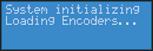
Startup
Note
To start your encoder, press the <POWER> button on the front panel.
While powering up, the encoder LCD readout will display the following series of messages:
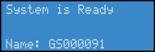
When System is Ready for operation, the encoder LCD display will alternate between status readouts that are similar to the following:
Shutdown
To shutdown the encoder, briefly press the <POWER> button on the front panel.
The encoder LCD readout will display the following messages:
After a few seconds, the encoder will power off.
Caution
Alternate Shutdown Method
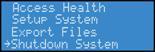
Alternatively, you can shut down the encoder by using the EASE menu.
Press the <MENU> button to display the EASE menu.
Using the <UP> and <DOWN> arrow buttons, scroll down until Shutdown System is displayed and selected.
Press <ENTER>.
Then, confirm that you wish to shut down the system using the <UP> and <DOWN> buttons to select either Yes or No. Press <ENTER>.
.
Starting an Encoding Session
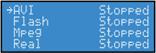
Press the <STREAM> button to start an encoding session using the front panel of your encoder.
The encoder LCD readout will display a list of available encoder profiles that can be used together with the current status of each.
Note
Use the <UP> and <DOWN> buttons to move the select arrow to point to the encoder profile that you want the encoder to use for this encoding session.
Once you select the encoder profile you need, press the <STREAM> button again to start the encoder.
The encoder LCD readout then displays messages about the encoder start process.
After the encoder session has successfully begun, the encoder LCD readout returns to the previous display of available encoders. The screen will indicate that the encoder profile you selected has begun encoding.
The video detection light illuminates if horizontal video sync is detected on either the S-Video or Composite video input of the encoder.
If the encoder you started was assigned to one of the EZStream ABC buttons, the corresponding button flashes and steady illuminates during and after the starting process.
By repeating this method, you can quickly start multiple encoders at the same time.
Cisco Digital Media Encoder 1100 is a single-channel encoder, which means that you can only connect and stream one audio and video source at any given time. However, you can stream the same audio and video at multiple data rates and multiple formats to provide the best user experience for different viewing audiences.
For example, you can stream Windows Media at Full resolution at 1500kbps and the same time stream Adobe Flash at CIF resolution at 500kbps on a Cisco Digital Media Encoder 1100.
Warning
Checking CPU Usage
Since you are able to start multiple streams, understanding how much of the processing power of the encoder is being used is invaluable. If you are using less than 50%, then you should be able to start another encoding session without adversely affecting system performance.
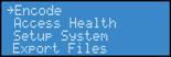
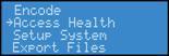
Press the <MENU> button to display the main menu on the encoder LCD readout.
The LCD readout will display the following menu choices:
Using the <UP> and <DOWN> buttons, move the arrow until it is next to the menu item Access and then press the <ENTER> button.
The LCD readout will display the Access menu choices. Press the <ENTER> button with CPU menu item selected.
The encoder LCD readout displays the amount of CPU cycles in use. When the encoder is idle (no encoder sessions running), the CPU percent displayed should be 4% or less. If one or more encoder sessions are running, then the percent displayed will be much higher and will fluctuate in a range of +/- 10 percentage points.
Press the <ENTER> button to return to the previous menu.
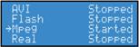
Stopping an Encoding Session
To stop an encoder, press the <STOP> button.
The encoder LCD readout displays the list of encoding and shows the current status of each session.
Using the <UP> and <DOWN> buttons, move the pointer to the position next to the encoding session you want to terminate.
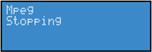
Press the <STOP> button again, and the encoder session selected will terminate.
To return to the main menu, press the <MENU> button.
Connecting an External Storage Device
The Cisco Digital Media Encoder 1100 front and rear panels each provide USB ports. You can connect almost any standard USB flash drive to one or both of these ports. This allows you to export any AV files you may have created on the encoder's local storage drive. The local storage drive is the D drive when you use the Save to File setting while you employ the Niagara SCX Web Interface.
When you insert a USB flash drive in one of the USB ports on the Cisco Digital Media Encoder 1100, the encoder automatically detects the removable storage device and assigns a random drive letter to the device. This device can capture files directly or can be employed to use the encoder Export File function, which is available for access when using the front panel menu.
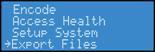
Exporting Captured Video Files
You can export your captured video files to an external USB drive.
Press the <Menu> button to access the encoder menu.
Using the <UP> and <DOWN> arrow buttons, highlight the Export Files option, and press the <Enter> button.
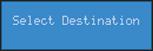
Then, select the To USB Drive option, and press <ENTER>.
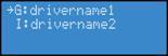
The next screen will ask you to select the drive destination and provide a list of active USB drives connect to the encoder.
Select the USB drive to which you wish to export, and press <ENTER>.
Once the encoder is finished exporting the file, you can remove drive.
Using the Unmount Button
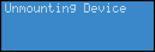
The Unmount button, a picture of which is shown directly below and which is located on the bottom left of your encoder, enables you to allow the encoder to unmount, or discontinue the operation of, a USB device.
When you initially press the Unmount button, the following two screens appear. In the second screen, use the <UP> and <DOWN> buttons to move the pointer to the position next to the USB drive session you want to terminate.
Select the USB drive to which you wish to export and press <ENTER>.
The USB session selected will terminate, and the following screens will appear.
The encoder then returns to the screen cycling of system information.
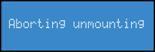
Should you decide to terminate the unmounting of a USB drive, when you see the Unmounting Device screen shown above, press the <MENU> button. In this scenario, the <MENU> button acts as an escape from the current unmounting session.
After pressing the <MENU> button, you will see a screen informing you the session is Aborting unmounting.
Once this screen returns to the screen cycling of system information, you can safely remove the USB device(s).
Note
The screen will remain at No USB Devices Found until you press the <MENU> button, which once again, acts as an escape from the current unmounting session. You will then see the following screen, and then the screen cycling system information will begin again.
Warning
DME Security Best Practices
We wrote topics in this section to answer and expand upon these customer questions about DME security:
•
•
•
Warning
In addition, some services are enabled by default that you might never use. We recommend that you disable all unneeded services.
•
•
•
•
•
Factory-Defined Login Credentials
Table 2-2 lists login credentials that are predefined on DMEs.
Table 2-2 Factory-Defined User Accounts and Passwords
GoStream
password1
—
—
—
X
Warning
If — despite our recommendation — you configure a DME to log into Windows automatically, password management becomes far more complex. Thus, any time that you neglect to change an auto-logon password specifically, you will prevent your DME from working as designed. See Other Required Password Maintenance (Only When Autologon Is Configured).
Niagara
password
X
X
X
—
SCXUser
viewcast
X
X
X
X
Used for the Niagara SCX service as well as the web service. This is not the user account that is used to log-in to Niagara SCX.
admin
admin
X
X
X
X
Used for the web-based administrative console on DMEs.
Login is possible only through a system from which your DME is reachable. Its connection to your DME might be either direct or networked.
1 In 5.2.187 and later releases on a DME 1000.
Changing Factory-Defined Login Credentials
Warning
Before You Begin
•
•
Procedure
Step 1
Harden Windows
Change the Windows password for the main account.
a.
•
•
b.
c.
Depending on your DME model type, the username is either Niagara or GoStream. See Table 2-2.
Step 2
Harden Niagara SCX
Change the password for the SCXUser account, which you use to log in to Niagara SCX Encoder Explorer.
a.
b.
c.
—
Step 3
Stop agent services
a.
•
•
—
Step 4
Update web.config to use the new password
Edit the web.config file.
a.
OR
Browse instead to one of the following:•
•
b.
c.
<identity impersonate="true"
userName="scxuser" password="viewcast"/>
d.
e.
—
Step 5
Restart your DME
—
Step 6
Check for errors
Point the DME web browser at http://localhost/encoderswebservice/, and then verify that the SCX service is available.
—
Step 7
Harden the web interface
a.
b.
c.
d.
e.
f.
g.
•
•
h.
The changed password takes effect immediately.
—
Tip
What to Do Next
•
•
Other Required Password Maintenance (Only When Autologon Is Configured)
Warning
If you disregard the warning against allowing automatic logins and you configure them nonetheless, you must take additional steps to ensure that logins occur as expected after you change the encrypted auto-logon password that Windows uses.
Procedure
Step 1
Alternatively, you can download this file as part of a Microsoft tools package at http://www.microsoft.com/windowsxp/downloads/powertoys/xppowertoys.mspx.
Step 2
Step 3
Step 4
Step 5
Step 6
Step 7
Note
Tasks to Complete After Changing DME Login Passwords
Procedure
Disabling Unneeded Services
Caution
If your DME enables and exposes any service that is not required, you can disable it. Possible examples of such services include NNTP, SMTP, and SNMP.
Procedure
Step 1
Step 2
Step 3
Step 4
•
•
Step 5
Step 6
After a Live Event Is Finished, Remove Its Encoded Video Files from the DME File Share
Caution
The file share uses a factory-default username and password, which you cannot change. Anyone who knows which network node is your DME and knows these login credentials can mount the file share and manipulate its files.
Advanced Operation: Using the Niagara SCX Web Interface
This section includes the following topics:
•
Accessing the Web Interface
The Niagara SCX Web Interface does not require software and works with any computer that has a current web browser, including Microsoft® Windows®, Macintosh, and Linux® machines. The Cisco Digital Media Encoder 1100 system must either reside on a shared IP network with the computer or can be directly connected to a Windows computer by using an Ethernet cable (RJ-45).
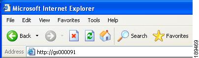
To access the Niagara SCX Web Interface, open the web browser on your computer and access the web interface by typing in the encoder machine name. The network name of the encoder is also its serial number and can be obtained from the LCD readout during the power up process.
If the encoder is already powered up, the serial number can be obtained from the LCD display while the system is idle.
At that time the encoder LCD display will alternate between readouts that are similar to the following display:
If the name is not immediately displayed on the System is Ready window, press the <UP> and <DOWN> arrow buttons to toggle through the system information until the name is displayed.
The serial number is also located on the bottom of the encoder.
Enter the encoder name in the web browser (as shown below), and press enter.
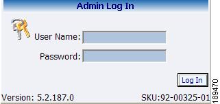
You will be prompted with a login screen that requires a user name and password. By default, the user name and password are both admin.
After logging in, you will have access to all of the web-enabled functions, including encoder operations, management, and system configuration tools.
Note
Starting an Encoding Session
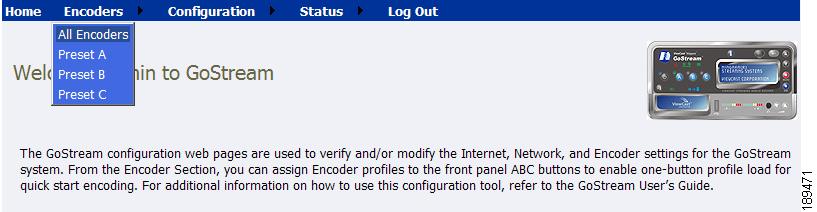
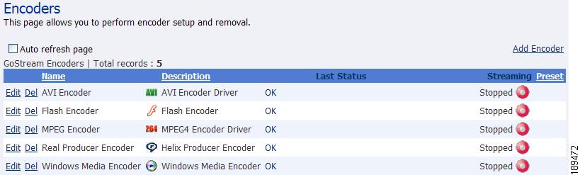
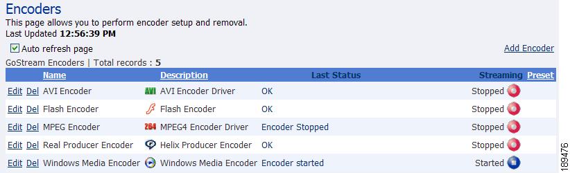
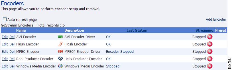
To start an encoding session, move the mouse pointer over Encoders in the menu bar, and click on All Encoders in the drop-down menu.
All of the encoder profiles loaded on the encoder will be presented in a list indicating format and current status.
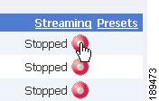
Press the red Stream icon located in the right column of the encoder you wish to start.
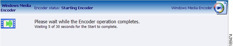
The web page automatically updates with messages detailing the encoder start progress.
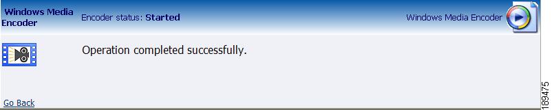
After the encoder has started successfully, the web page will return to the All Encoders page with the encoder status updated to reflect the Started mode.
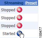
Stopping an Encoding Session
If you are not already on the All Encoders page, move your mouse over Encoders in the menu bar and click All Encoders in the drop-down menu.
This will bring you to a web page similar to the following.
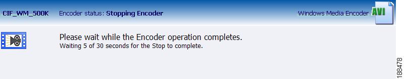
Press the blue icon, which indicates it is a streaming encoder, located in the right column of the encoder you wish to stop.
The web page automatically updates with messages detailing the encoder stop progress.
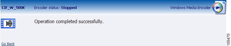
After the encoder has stopped successfully, the web page will return to the All Encoders page with the encoder status updated to reflect Stopped mode.
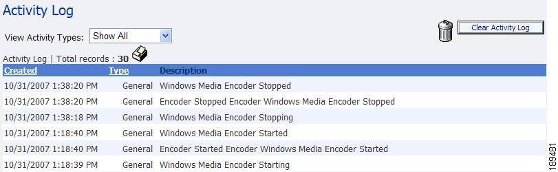
Viewing the Activity Log
The Activity Log records the Encoder Start and Stop events. To view the Activity Log, move the mouse pointer over Status in the menu bar, and click on Activity Log in the drop-down menu.
The log is updated for every event on the encoder. The log now includes the starting and stopping events for the encoder from the "Starting an Encoding Session" section and "Stopping an Encoding Session" section.
Each event is date and time stamped. Pressing the Clear Activity Log button in the upper-right clears all logged activities.
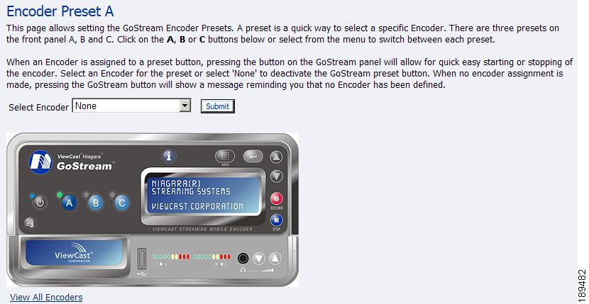
Configuring the EZStream Buttons
The encoder provides one-button streaming via the EZStream buttons located on the front panel of the system. By default, these buttons are not assigned to an encoder. The Niagara SCX Web Interface is used to configure each button to a specific encoder.
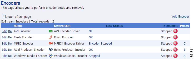
Move your mouse pointer over Encoders in the menu bar, and click Preset A in the drop-down menu.
You are presented with the configuration page for the EZStream A button. This page contains a graphic representation of the front panel of the encoder. The A button is highlighted on this graphic representing that you are actively assigning an encoder to this corresponding EZStream button.
Click the drop-down list next to Select Encoder. This provides the complete list of encoders available on the system.
Select the encoder you wish to assign, and click the Submit button.
The web page will update the preset A and provide a message reporting Encoder Preset: A updated successfully.
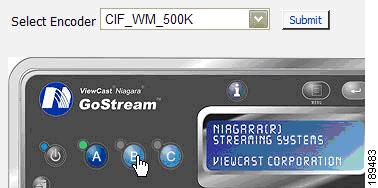
By clicking on the B and C buttons on the encoder graphic, you can assign encoders to the EZStream buttons, as shown in the following diagram.
After assigning encoders to the A, B, and C buttons, the Presets column on the All Encoders page updates to reflect these changes.
Note
The following sections show what each encoding format property page looks like. For more information on setting up each type of encoder, see the "Editing an Encoder Profile" section.
•
•
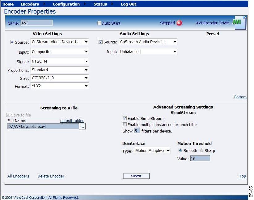
AVI Encoder Properties
Flash Encoder Properties
MPEG-4 Encoder Properties
Real Encoder Properties (Helix)
Windows Media Encoder Properties
Editing an Encoder Profile
When you create a new encoder, you will be prompted to edit the new profile to your specific encoder settings and requirements. You can also edit the existing encoder profiles that are provided by default on the Cisco Digital Media Encoder 1100. The property windows for editing a new encoder or an existing encoder are identical.
If you have performed the steps for adding an encoder, you should already see the Encoder Properties page.
If not, you can edit an existing encoder profile. Go to the All Encoders screen.
Click the Edit link next to the encoder whose properties you wish to modify.
The properties page for that encoder is then displayed.
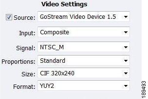
Video & Audio Settings
Regardless of the encoder type, all types require that you set the audio and video properties. These values are the same for all encoder types except for the added color space setting for AVI and MPEG-4.
You can enable or disable video and/or audio by clicking the check box next to Source. When enabled, the Source, Input, Signal, Proportions, Size, Format, and Input fields can be edited.
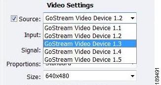
Although the Cisco Digital Media Encoder 1100 is a single channel encoder, meaning you can only capture from one physical audio and video source at any given time, you can capture multiple streaming formats and resolutions simultaneously from the same video source. To accomplish this, the video source is seen as multiple inputs denoted by incrementing decimal values. They appear in the following manner:
Warning
Set Input for both video and audio to match the connectors on the back of the encoder to which you have connected your video and audio source. This could be Component, Composite or S-Video for video input and Balanced or Unbalanced for audio input.
When you performed the First Start Setup, you determine if your video signal was NTSC or PAL. The Signal field adds granularity for regional NTSC, PAL, and SECAM settings. If you are uncertain which setting applies, refer to the owner's manual for the video source you have connected to the encoder hardware.
The Proportions setting uses the term Standard, meaning square pixels for a VGA monitor, and CCIR-601, meaning elongated pixels for a TV monitor. Choose the setting that reflects the type of display on which your content will be viewed. For example, if you will be streaming your video on the Internet to be viewed on a computer monitor, select Standard. If the inaccurate setting is selected, your streaming video will be distorted.
The Size field refers to the pixel size of the encoded video. The standard sizes are as follows:
•
•
•
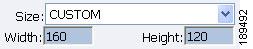
You can also specify a custom size for your video except in the Flash encoder where only specific sizes are allowed. This is useful when capturing video to be played on a mobile video device that requires a non-standard size for compatibility.
In all other encoders except Flash, if you select Custom from the drop-down menu, two additional fields will appear allowing you to type in the exact size you want the resulting video to be.
Note
Now that you have completed all of the Video and Audio settings, you can proceed to the encoder type settings at the bottom of the page. As previously stated, these settings will vary according to the encoder type.
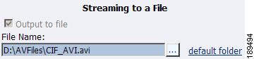
AVI Encoder Settings
AVI is an uncompressed audio and video storage format and, therefore, only has the ability to save to a file. You can type in a unique name for the generated AVI file and modify the directory path to the location the file will be stored. Clicking the Default Folder link will insert the path of the default folder for file storage on the encoder. By default the path is d:\AVFILES\.
Note
Once you have saved your file to the encoder internal hard drive, we recommend that you move the drive to another external storage device such as a USB drive or a network drive for backup purposes.
After you have input your settings, click the Submit button at the bottom of the page to save your changes.
Warning
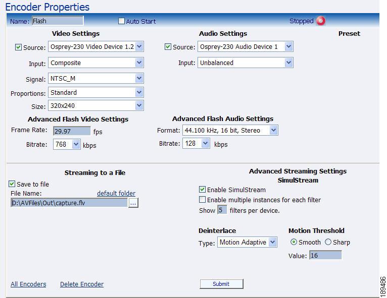
Flash Encoder Settings
Encoder Settings Web Interface
The Cisco Digital Media Encoder 1100 includes Adobe Flash capabilities for streaming to a file. The Niagara SCX Web Interface provides option settings for live and file based streaming.
The following figure illustrates the screen you will see after creating an encoder through the Niagara SCX Web Interface.
The Flash encoder settings are similar to the AVI settings for saving the audio and video to a file. To enable streaming to file, ensure the Save to File box is selected. Flash adds some additional frame and bit rate controls. The frame rate changes the frames per second that the video will be encoded. The audio Format setting can be used to modify the audio frequency and changes stereo to mono. The Bitrate settings pertain to the amount of data per second the audio and video are captured. Decreasing the bit rate for both or either will decrease the playback viewing quality.
The Flash encoder creates a Flash format audio and video file. You can type in a unique name for the Flash file (.flv).
After you have input your settings, click the Submit button at the bottom of the page to save your changes.
Warning
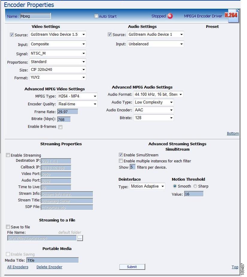
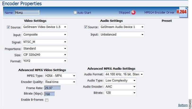
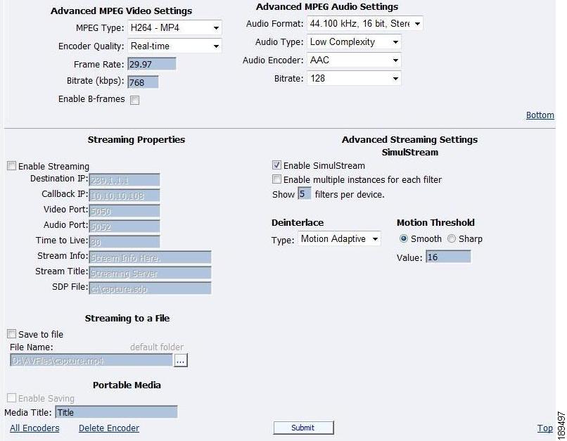
MPEG-4 Encoder Settings
The Cisco Digital Media Encoder 1100 software MPEG-4 compression engine provides H.263, MPEG-4 Part 2 SP/ASP, and H.264/MPEG-4 Part 10 Baseline encoding functionality. This product provides the capabilities to encode streams for Internet video, mobile phones, set top boxes and create media files for other MPEG-4 compatible devices such as iPods®.
The Niagara SCX Web Interface provides options for basic and advanced settings for the video and audio options of MPEG-4 available with the encoder.
The following figure illustrates the screen you will see after creating an encoder through the Niagara SCX Web Interface.
The Advanced MPEG Video Settings provide you with the ability to choose the MPEG Type required for your output. These MPEG Types include the following:
•
•
•
•
Note
•
•
–
–
•
Note
•
•
Note
Note
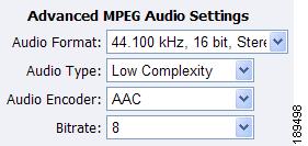
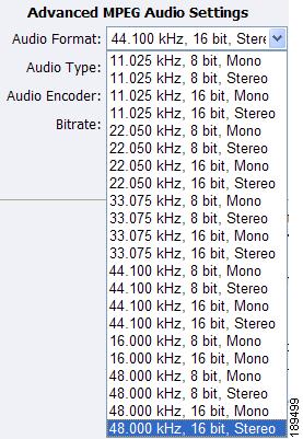
The Advanced MPEG Audio Settings, provide you with several Audio Formats, Audio Types, Audio Encoders, and Bitrates from which to choose. These choices include several options as to audio sampling, and whether the audio is to be encoded monophonically (mono) or stereo.
The Audio Type setting is only related to AAC Encoding. If you select AMR in the Audio Encoder field, this setting is not used. The Audio Type field provides you with a drop-down box, which includes the following two choices:
•
•
Note
The Audio Encoder settings provides you with a drop-down box, which includes the following three choices:
•
•
•
Note
The Audio Bitrate drop-down box provides you with several choices, ranging from 8 to 320.
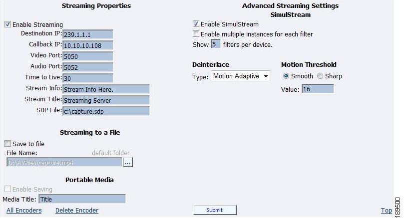
The web interface for the encoder includes options for Streaming Properties and Advanced Streaming Properties. As to the broadcast type you choose, you have the option to check the Enable Streaming box. Please see the "Real Encoder Properties (Helix)" section for a more detailed description of enabling pull. Other options provide you the abilities to Stream to a File and to Portable Media.
Note
For streaming to a file, you must type in a unique name and location for this file. Check the Portable Media box if you would like to save the encoded content to a file. Enter a file destination in the field provided.
Note
When SCX Manager and SCX Explorer are not on the same computer, always start your browse for files at My Network Places and work down or enter the entire file pathname beginning with the system name (for example, \\fileserver\c\videos). If you simply enter a file name, you may inadvertently browse your local computer when the media file resides on the remote computer.
To stream your MPEG-4 content, select Enable Streaming. Set the appropriate streaming properties.
Note
The save SDP File field will require a name and destination path for the resulting SDP file created when the stream is started. If you are streaming to a Helix®, a Quicktime, or a Darwin server, refer to its respective documentation or online message boards for setup details specific for the individual streaming server.
Note
For example, if you want another PC to view the stream, save the SDP file to a share folder on the local drive. The other PC can open the SDP file and the stream can be played in a Quicktime or other MPEG-4 compatible streaming player. Since MPEG-4 encoding can be CPU intensive, it is not recommend that you view the stream on the same system as the encoder unless you have a very powerful system (dual-core processors or better). Doing so may overtax the host CPU which will cause video quality degradation and encode session failure.
After you have input your settings, click the Submit button at the bottom of the page to save your settings.
Warning
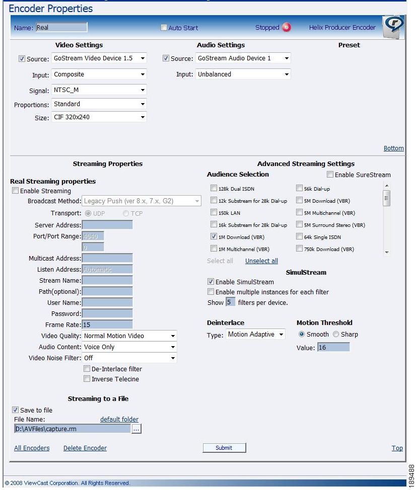
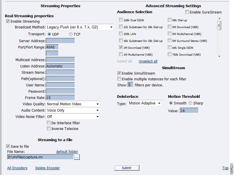
Real Encoder Settings (Helix)
Real (Helix) is both a storage format and a streaming format. In addition to the ability to output to a file, the Real Encoder can stream to a Helix Server. The settings for the Real Encoder include the ability to adjust parameters for connecting and streaming to the server.
Broadcast Method: There are several different broadcast types for streaming Real format video to a Helix Server, as follows:
•
•
•
•
•
Transport Protocol: When you use a push broadcast method, you specify whether to use UDP or TCP upon delivering the broadcast stream to Helix Server. UDP is the preferred protocol due to the lower network overhead. But you may want to use TCP when delivering the broadcast over a lossy environment.
For the Server Address field, enter the IP address or DNS name of the Helix Server used for the broadcast, such as 207.188.7.176 or helixserver.example.com.
For the Port/Port Range field, specify the HTTP port on Helix Server. The default value is port 80, which is the server's default HTTP port. If multicasting, indicate the range of ports on the Helix Server receivers where the broadcast packets will be sent. The encoder and Helix Server negotiate the actual ports to use once the broadcast begins. The default range is from 30001 to 30020.
If using a Multicast Address, enter the multicast address for the broadcast stream in the Multicast Address field. The Multicast Address must be in the range 224.0.0.0 to 239.255.255.255.
The Listen Address field is the IP address of your machine where Helix Producer will listen for resend requests from the server.
The listen address sets the IP address that Helix Mobile Producer Live uses to listen for packet resend requests from Helix Server. For the listen address, you can use one of the following possible values:
•
•
•
•
If your Helix Mobile Producer Live machine has multiple IP addresses, enter the IP address that Helix Mobile Producer Live should use for communications from Helix Server. If you are broadcasting through a firewall performing network address translation (NAT), set the listen address to the IP address of the firewall or the value 0.0.0.0. The 0.0.0.0 value tells Helix Server to allow a Helix Mobile Producer Live connection from any IP address. The connection still requires the valid password, however.
In the Stream Name field, enter a name for the broadcast stream. This name resembles a clip name and should use the appropriate extension, either .rm for a constant bit rate stream or .rmvb for a variable bit rate stream. This name appears in the broadcast URL.
The Path (optional) field specifies a virtual path, which can be used for archiving or splitting on Helix Server. Use a simple name followed by a forward slash, such as news/.
In the User Name and Password fields, enter the User Name and Password defined in each Helix Server receiver definition. The broadcast connection fails if the value is incorrect.
Frame Rate, or frame frequency, is the measurement of the frequency (rate) at which an imaging device produces unique consecutive images called frames. The term applies equally well to computer graphics, video cameras, film cameras, and motion capture systems. Frame rate is most often expressed in frames per second (fps), or simply hertz (Hz).
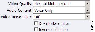
The next series of fields activate the Real Encoder's filters to improve video and audio quality. These filter settings will depend upon the type of content you are streaming and your subjective preference. It is recommended you experiment with these settings and view their results on a test capture.
The Cisco Digital Media Encoder 1100 features integrated de-interlacing and inverse telecine filters that automatically apply when needed. This allows the encoder to perform at maximum efficiency. We recommend that you do not enable the Real Encoder de-interlace and inverse telecine filters since applying filters multiple times can produce undesirable results and consume additional system resources.
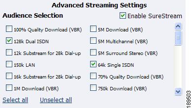
Enable SureStream™: SureStream allows you to encode the broadcast stream for multiple audiences. However, each primary stream or substream you choose increases the processor load during encoding and adds to the outgoing bandwidth requirements. For example, with SureStream enabled, you can choose the 56k Dial-up audience and the 128k Dual ISDN audience. In addition, with SureStream enabled, the encoding might require twice as much processing power.
Regardless of whether or not you enable SureStream, you must choose at least one Audience Selection for your stream.
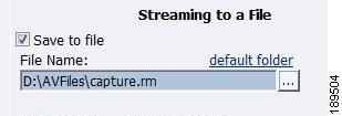
You can also choose to output to a file while streaming or output only to a file. Type in a unique name for the file.
Note
After you have input your settings, click the Submit button at the bottom of the page to save your changes.
Warning
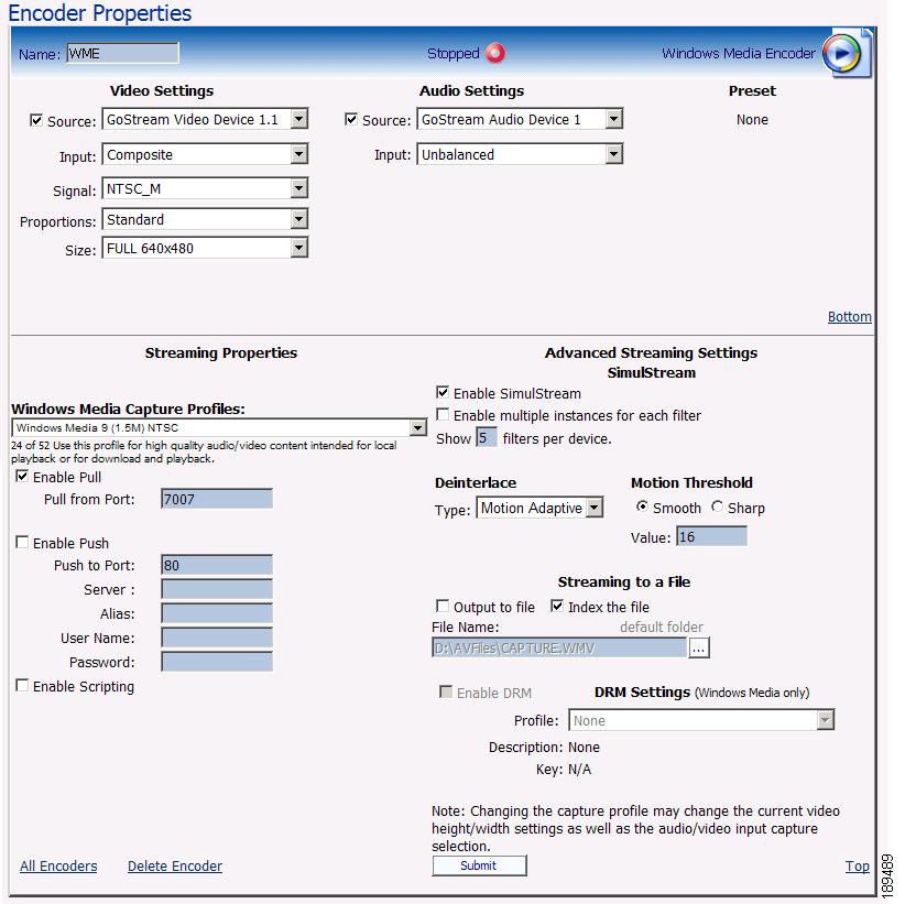
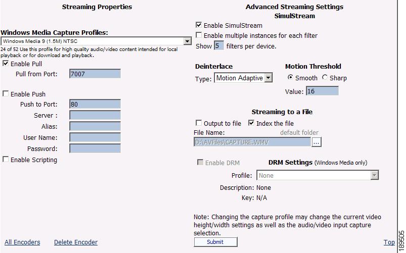
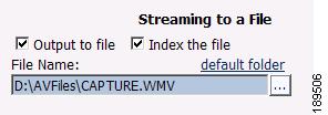
Windows Media Encoder Settings
Windows Media is both a storage format and a streaming format. In addition to the ability to output to a file, the Windows Media encoder can stream to a Windows Media Server. The settings for Windows Media encoder include the ability to set parameters for connecting and streaming to the server.
First, select a Windows Media Capture Profile from the drop-down menu.
Note
When streaming audio and video, there are two methods of delivery, as follows:
•
•
To enable clients to pull the stream from Cisco Digital Media Encoder 1100, you set up a session and begin broadcasting directly from the encoder. Clients (Windows Media servers or players) can connect to the stream at any time by using the following URL format:
•
•
By default, the encoder supports up to 50 direct connections during a broadcast.
Note
Select the Enable Pull check box. Then, enter a port number that will be used by the server to pull the stream from the encoder.
Note
Select Enable Push and enter a port number that is not assigned to another encoder. Then, enter the server name or IP address, Alias (optional), user name, and password.
You can also choose to output to file at the same time you are streaming to a server. However, you can set the server to archive the file and streaming, allowing the encoder to reserve its system resources for encoding. Refer to the Windows Media Server documentation for details.
If you check Index the file, viewers will be able to direct access any point within the Windows Media® file using the Windows Media player. Indexing is also required for editing the Windows Media file using Microsoft Windows Media Utilities.
After you have input your settings, click the Submit button at the bottom of the page to save your changes.
Warning
The Niagara SCX Web Interface will then display the All Encoders list.
Deleting an Encoder Profile
You can also delete encoder profiles from the encoder. It is valuable to remove encoders you will not use, as every encoder profile, regardless if active or idle, uses active memory.
Note
Note
To delete an encoder profile, you must access the All Encoders list in the Niagara SCX Web Interface.
You can delete an encoder by clicking the Del link next to the encoder you wish to remove.
Alternatively, you can click the Edit link to view the encoder profile, verify that it is the encoder that you wish to remove.
Then, click the Delete Encoder link at the bottom of the page once you have verified that it is the encoder you want to delete.
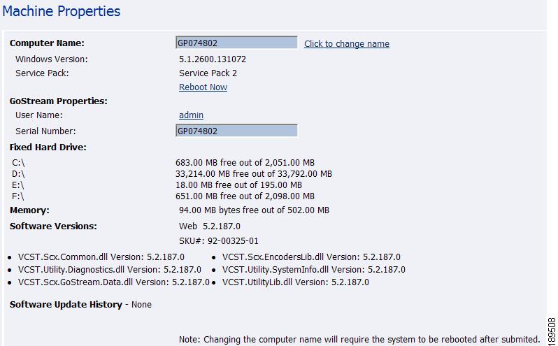
My Cisco Digital Media Encoder 1100
The My Encoder page provides details on software versions, network name, serial number, and hard drive configurations. Most of the data on this page is for informational purposes and cannot be altered. However, the following two fields allow modifications:
•
•
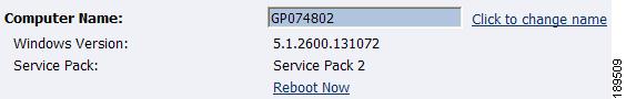
Computer Name
The Computer Name field contains the current network name for the encoder. This is the same name that you typed into a web browser to access the Niagara SCX Web Interface. You can change the Computer Name by clicking the Click to change name link next to this field.
The screen will refresh and now the Computer Name field is an editable text field. Type in a new name for the encoder.
Then, click the Submit button at the bottom of the page.
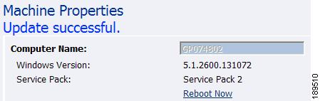
The page will refresh and you will be prompted to reboot the encoder. Your changes will not take effect until the system is restarted.
Click the Reboot Now link to restart the system and apply the Computer Name change.
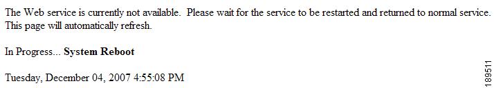
While the encoder is restarting, the following message will appear in the web interface.
Note
When encoder has restarted, you will be returned to the Login screen.
Note
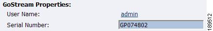
Cisco Digital Media Encoder 1100 Properties
The encoder Properties section has two fields: User Name and Serial Number. Only the User Name field allows modification, which changes the User Password from the factory default.
•
•
Changing the Login Password from the Factory Default
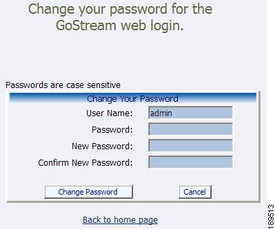
Click the admin link in the User Name field. You will be presented with a new screen that allows you to change your login password for the Niagara SCX Web Interface.
Note
Type in your current password in the Password field and then type in the new password in both the New Password and Confirm New Password fields.
Note
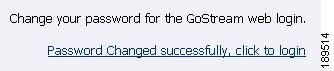
Then, click the Change Password button. You will then be presented with the following results:
Note
Restoring the Login Password to the Factory Default
If you have forgotten or lost your password, you can restore the default password by running the Restore Factory Defaults option. For more information, see the "Restore Factory Defaults" section.
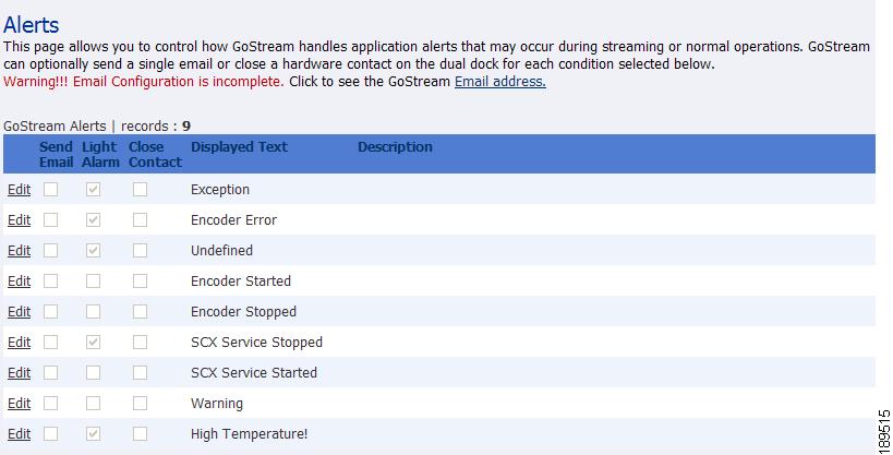
Cisco Digital Media Encoder 1100 Alerts
The following is a representation of a page that allows you to control how the encoder handles application alerts that may occur during streaming or other operations. Cisco Digital Media Encoder 1100 can optionally send an email to multiple recipients and light the alarm light on the front panel of the encoder.
Email Alert
You can optionally send an email alert to specific email address in the event of an application alarm. Checking Send Email will enable this feature. You must specify the email address to which an alert will be sent, along with your email server user name, password, and server name. For more information about configuring Cisco Digital Media Encoder 1100 to send email alerts, see the "System Configuration Settings" section.
Alarm Light
Checking the Light Alarm box will instruct the encoder to light the front panel alarm light.
Edit Alert Settings
To edit the settings for each alert listed, click the Edit link in the row of the alert you want to modify.
Once you have made your modifications to the alert settings, click the Update link to enter your settings and return to the encoder Alerts list.
View Alerts
All alerts defined on the encoder Alerts page are logged on the View Alerts page when those alerts occur. Once a user has cleared an alert by using the Help or i button on the front panel of the encoder, the alert is cleared from the View Alerts log page.
Alternatively, the Cisco Digital Media Encoder 1100 system informs you of an alert when the Alarm Indicator Light on the front panel of the system turns red. When this occurs, to determine what the alert is, you must press the Help or i button, which will cycle the alert occurring.
For more information, see the "The Help, or "i" Button, the Niagara SCX Web Interface, and Their Alert Settings" section on page 3-55.
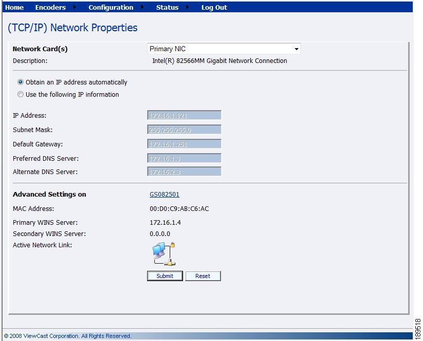
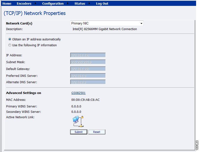
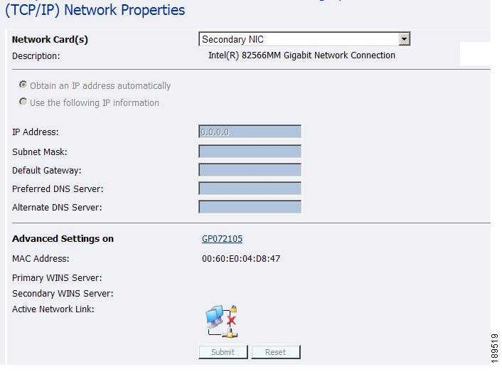
Network Properties
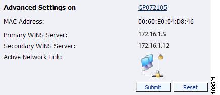
The Network Properties page provides detailed information on the encoder's current network settings for the Network Interface Card (NIC). In the example below, the Advanced Settings on the Primary WINS Server and the Secondary Wins Server appear due to the Cisco Digital Media Encoder 1100 system running on Windows® servers.
Should the Cisco Digital Media Encoder 1100 system not be running on Windows servers, the screenshot below, or a similar screenshot, appears.
If the following screenshot appears, please note no Ethernet cable is attached from the encoder system into a server. Note the statement Verify the network cable to enable network setting updates! and the icon at the bottom of the screen indicating a disconnect.
Network Card(s)
Cisco Digital Media Encoder 1100 has two network connections: a primary connection and a secondary connection. To view the current properties for each card, select the card you wish to view from the drop-down menu in the Network Card(s) field.
Advanced Settings (Network)
Advanced Settings provides the encoder network name, MAC Address and server IP address settings.
The encoder network name is a link. If you click this link, you will be directed to the My Encoder page. From this page you can change the encoders's network name. For more information, see the "Computer Name" section.
The Active Network Link field uses two icons to indicate whether the network interface card selected has a network connected.
Table 2-3 Network Link Icons and Descriptions
The network link is detected.
The network link is not detected.
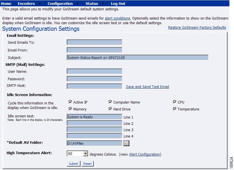
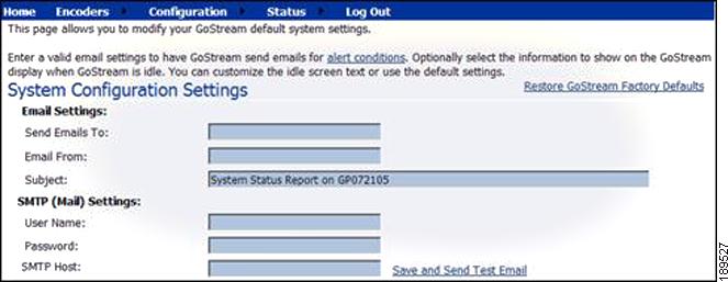
System Configuration Settings
The System Configuration Settings page allows you to modify your encoder default system settings. You can configure email settings so that Cisco Digital Media Encoder 1100 can send an email to predefined email addresses whenever the encoder encounters an alert condition. You can also customize the information that the encoder displays on its front panel when the system is idle.
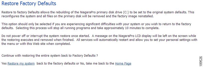
This page also provides the ability to restore your encoder to its original factory disk image, returning all of the system settings to their original state. Using the Restore Factory Defaults option will remove all custom settings and takes approximately 10 minutes to complete.
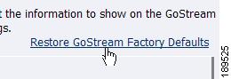
Restore Factory Defaults
Click the Restore Factory Defaults link to start the process.
The following screen gives details of the process that you are about to execute and allows you the opportunity to cancel the process.
Note
Note
Email Settings
If you are unfamiliar with setting up an SMTP email account for sending email, please contact your network administrator for assistance.
To configure encoder Email Settings, you will need to enter the following information:
•
•
•
•
–
–
–
Note
Note
Once you have entered the information above, click the Submit button to save your changes.
You can test your settings by clicking the Save and Send Test Email link. The resulting page will report if the email was successfully sent or there was a send failure.
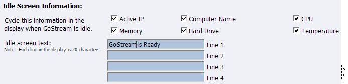
Idle Screen Information
This section allows you to modify the information that is displayed in the encoder LCD display on its front panel.
Check the boxes next to the information you wish to be displayed. This information is cycled as the LCD display alternates between status information and encoder information.
At the top of the LCD idle screen is the default message System is Ready. You can customize this message.
Once you have entered the information above, click the Submit button to save your changes.
Default Directory Setting
Note
Note
Note
The Default AV Folder is the directory that the encoder stores AV files created whenever you select the Save to File option in an encoder profile. Refer to the Save to File option under the AVI Encoder Properties, Flash Encoder Properties, MPEG-4 Encoder Properties, Real Encoder Properties (Helix), and Windows Media Encoder Properties sections for information about setting an encoder profile to create an AV file.
High Temperature Alert
You can enable an alert if the encoder reaches a predefined maximum temperature level. To set the level, select from the High Temperature Alert drop-down menu.
The Alert Configuration links to the Alerts page. For information on setting the Alerts, refer to the "Cisco Digital Media Encoder 1100 Alerts" section.