Feedback
Table Of Contents
Getting to Know Your Cisco LCD Professional Series Display
About Controls and Sensors on the Front of Your LCD Display
About Terminals on the Back of Your Display
Locking Front Panel Controls and the Remote Control
Mechanical Layout — LCD Professional Series 100 (40" Display)
Mechanical Layout — LCD Professional Series 110 (52" Display)
The Basics
Revised June 22, 2009
•
Getting to Know Your Cisco LCD Professional Series Display
Package Contents
Verify that the following items are the product kit. If any items are missing, contact your dealer. Contact a local dealer to buy optional items.
•
•
•
Note
•
•
•
•
–
–
–
–
–
Getting to Know Your Cisco LCD Professional Series Display
The arrangement and availability of particular features on the front and back panels differs slightly among different LCD display models in the Professional Series. For example, the 52" model has a brightness sensor on its front panel that the 40" model does not have. Also, the 52" model has BNC/Component interfaces on its back panel that the 40" model does not have.
•
•
•
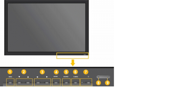
About Controls and Sensors on the Front of Your LCD Display
Figure 2-1 Front—40"
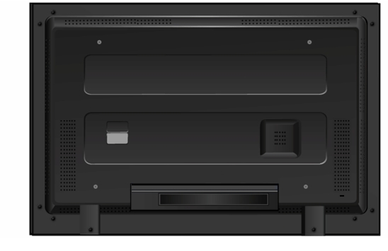
About Terminals on the Back of Your Display
Figure 2-2 Back—All Display Sizes
A recessed area on the back of your display partially hides the power switch, the Kensington slot, the electrical socket, and the terminals where you connect signal cables. A large white sticker clearly identifies each available feature in this area. Feature availability varies among different display models but your display is likely to have at least these:
•
•
•
•
•
•
•
•
•
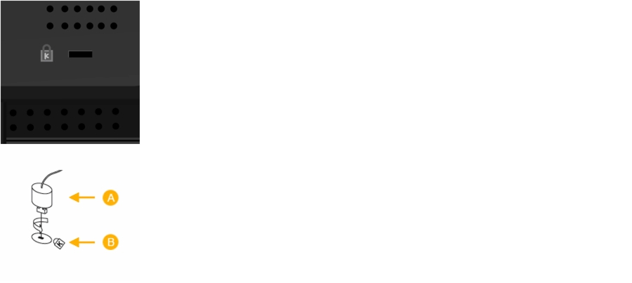
Using the Kensington Slot
Kensington locks are devices used to physically secure a Cisco LCD Professional Series display that is in a public place. The locking device is sold separately. The appearance and locking method may differ from Figure 2-3, depending on the manufacturer.
Figure 2-3 A Typical Kensington Lock
See the manual provided with your Kensington lock to understand its proper use. The location of the Kensington slot might differ on various Cisco LCD Professional Series display model types.
Procedure
Step 1
Step 2
Step 3
Step 4
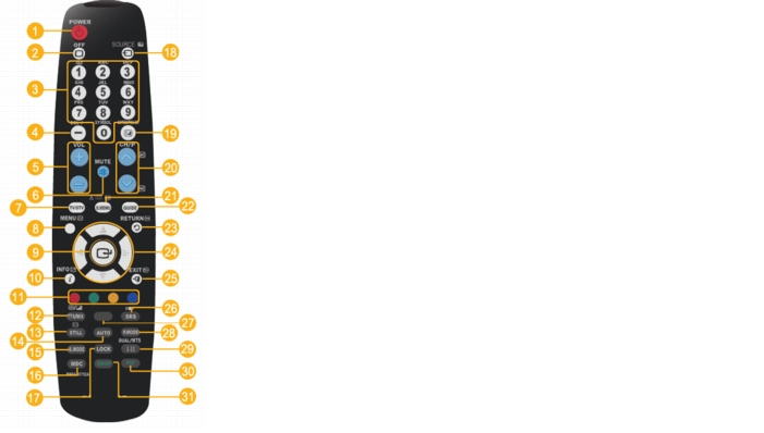
About the Remote Control
When a TV or other electronic device is near your Cisco LCD Professional Series display, the remote control might perform poorly or malfunction due to interference with the frequency.
Figure 2-4 Button Map
Power on
.
Not available.
Not available.
Power off
.
Not available.
Return
— Returns to the previous menu.
Number buttons — Press to change the channel.
Still — Press once to freeze the screen. Press it again to unfreeze. Audio continues without interruption.
Up/Down/Left/Right buttons — Moves from one menu item to another horizontally or vertically, or adjusts values in the selected menu.
Not available.
Not available.
Exit
— Exits from the active menu.
Audio volume +/-.
S.Mode — Shows on screen which preconfigured stereo mode is active. Press again to cycle through modes.1
Surround Sound
— SRS TS XT.
Mute
— Mutes audio output temporarily and shows an icon on the lower left of the LCD panel. To restore audio output, press MUTE or press - VOL +.
Not available.
Not available.
Not available.
Lock — Activates or deactivates all function keys on both the remote control and the LCD display except for the Lock button.2
P.Mode — Shows on screen which preconfigured picture mode is active. Press again to cycle through modes.3
Menu — Opens the calibration (OSD) menu and exits from it.
Source
— Changes the input signal source. Changing the source is permitted only for external devices that are connected to the display.
Not available.
Select
— Activates a highlighted menu item.
Not available.
Not available.
Info
— Current picture information is displayed on the upper left corner of the screen.
Not available.
Not available.
Not available.
1 Cisco LCD Professional Series displays include a built-in high fidelity stereo amplifier with five preconfigured modes: Standard, Music, Movie, Speech, and Custom.
2 To learn how to use this feature, see Locking Front Panel Controls and the Remote Control. To learn how to change the PIN, see Editing the 4-digit PIN from the Safety Lock PIN Menu, page 4-14.
3 Cisco LCD Professional Series displays are preset with four picture modes: Dynamic, Standard, Movie, and Custom.
Locking Front Panel Controls and the Remote Control
You can protect your LCD display from unauthorized use by locking the controls on its front panel and locking the buttons on your remote control. While they locked, all of these features are unavailable, except buttons that you use on the remote control to enter a secret PIN and thereby regain access.
Procedure
Step 1
Step 2
Our factory default values are well known for the PIN, which is not secret until after you change it from the factory default. The default is 0000 for 40" LCD displays and 1234 for 52" LCD displays.
Related Topics
•
•
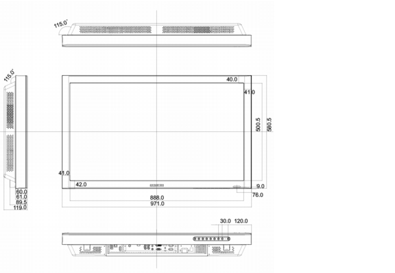
Mechanical Layout — LCD Professional Series 100 (40" Display)
Figure 2-5 LCD-100-Pro-40N
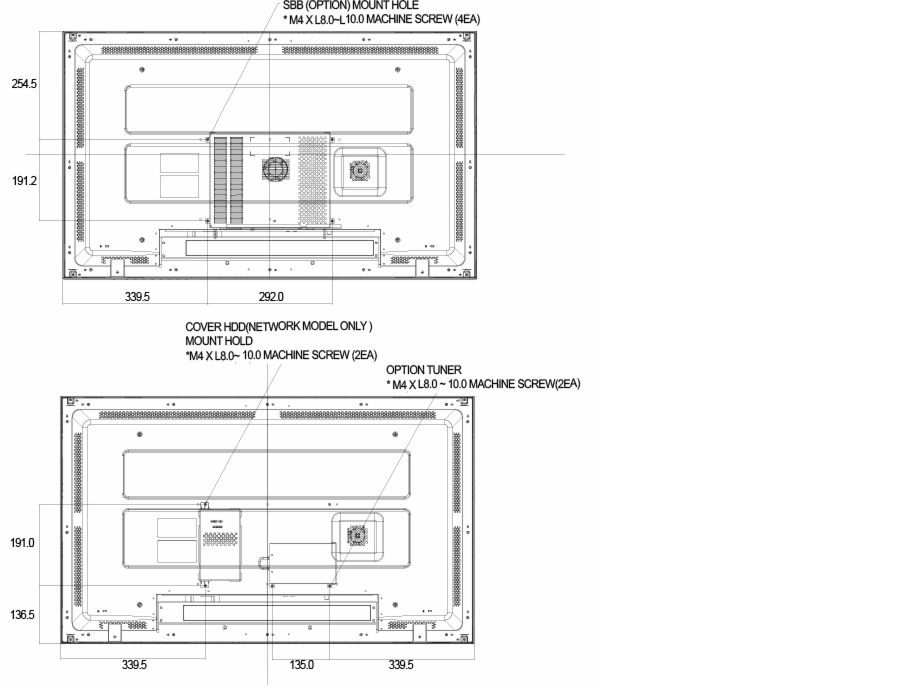
Figure 2-6 LCD Display Head for 40" Display
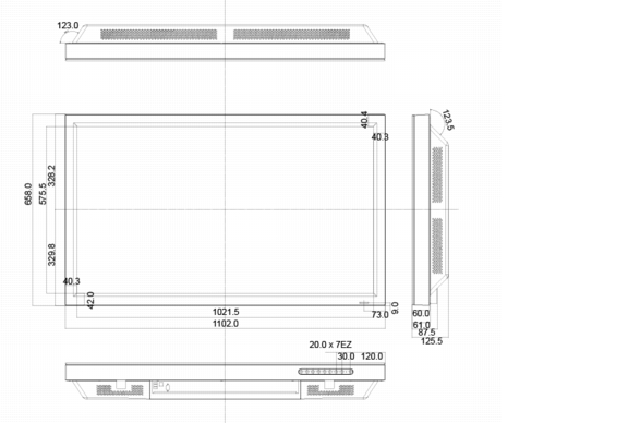
Mechanical Layout — LCD Professional Series 110 (52" Display)
Figure 2-7 LCD-110-Pro-52S
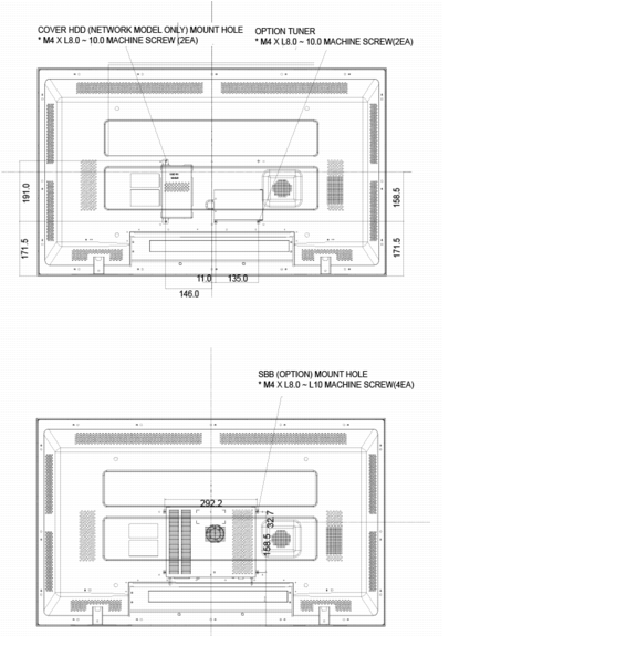
Figure 2-8 LCD Display Head for 52" Display
Installing VESA Brackets
VESA brackets are optional, installed at your discretion, and Cisco is not responsible for any product damage or any injury arising from VESA bracket installations. When you use VESA brackets with Cisco LCD Professional Series displays, be sure to comply with international VESA standards.
We recommend that you schedule an installation by licensed contractors who can visit your site and install the bracket.
To understand safe handling practices for your Cisco LCD Professional Series display, see the "Important Safety and Compliance Information" chapter in this guide.
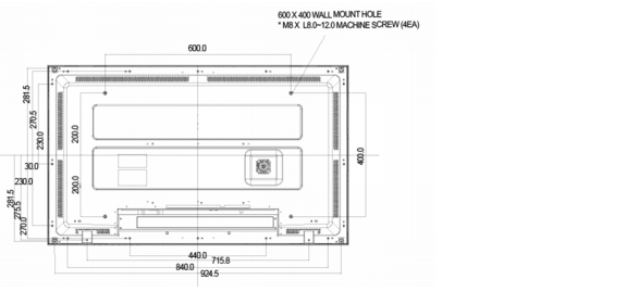
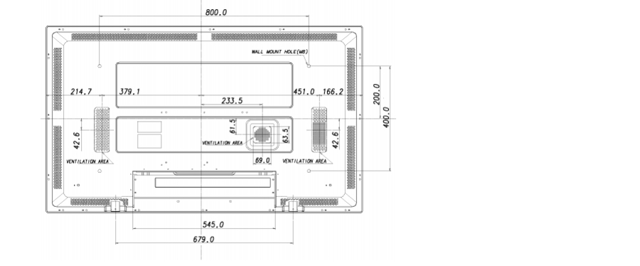
In the LCD Professional Series, VESA mounting interface dimensions are:
•
•
Figure 2-9 40" VESA Bracket Dimensions
Figure 2-10 52" VESA Bracket Dimensions
Note