Feedback
Table Of Contents
Routing Inbound PSTN Calls in a Single-Zone Network
Routing Inbound PSTN Calls in a Multi-Zone Network
Routing Inter-Zone Calls Using Hopoff Statements
Routing Inter-Zone Calls Using a Directory Gatekeeper
Routing Using the Border Element
Routing Calls to Other Networks
Call Routing
Last revised on: October 30, 2009
This chapter describes various call routing methods used by Cisco gatekeeper and Cisco Unified Videoconferencing equipment in an H.323 video network. Calls can be routed to and from many types of devices in a variety of ways.
What's New in This Chapter
Table 7-1 lists the topics that are new in this chapter or that have changed significantly from previous releases of this document.
Table 7-1 New or Changed Information Since the Previous Release of This Document
Routing calls through untrusted networks
Routing calls to other networks
Call Routing Scenarios
There are four possible call routing scenarios in an H.323 network:
•
H.323 endpoint to H.323 endpoint using the E.164 address
Routing calls between H.323 endpoints is the simplest type of call routing in an H.323 network. To dial within a single zone, the endpoint initiating the call enters the E.164 address of the endpoint being called. (In most cases, the E.164 address is a video terminal extension). If the call is an inter-zone call, the initiator must enter the zone prefix and terminal extension. Using this type of dial string is similar to dialing outside the local area code in a telephony system. In multi-zone networks, service prefixes for Multipoint Control Units (MCUs) should contain the zone prefix.
•
To use the H.323-ID to route calls between H.323 endpoints, the calling station must dial the H.323-ID of the video terminal being called. H.323-IDs are supported only for calls from video terminal to video terminal or from video terminal to Video Terminal Adapter (VTA). When using a VTA, exercise care in addressing because some H.320 units cannot send alphanumeric strings. In these cases, E.164 addresses are the only usable route table mechanism. Between zones, Domain Name Service (DNS) may be used to reach the H.323-ID of an endpoint registered to a remote gatekeeper. To use DNS, the calling station dials H.323-ID@Domain, which allows the gatekeepers to resolve the remote zone destination using DNS.
•
Routing calls from an H.323 endpoint to a service is also simple. In a single zone, an H.323 endpoint dials the service prefix followed by either the conference ID (for an MCU call) or the Integrated Services Digital Network (ISDN) telephone number of the H.320 endpoint. The service prefix can also route inter-zone calls to services, but in this case the service prefix contains the zone prefix for the MCUs, and the inter-zone calls use hopoffs for gateways.
•
You can use any of the following methods to route calls from the Public Switched Telephone Network (PSTN) to H.323 endpoints or services:
–
–
–
–
For more details on these routing methods, see Routing PSTN Calls to H.323.
Example
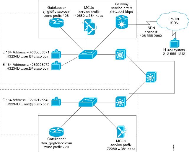
Figure 7-1 illustrates a multi-zone network with video terminals and services in each zone. The following dial strings apply to the scenarios in Figure 7-1:
•
Intra-zone call, User1 to User2 — User1 dials 4085558072
Inter-zone call, User1 to User3 — User1 dials 7207125543
•
Intra-zone call, User1 to User2 — User1 dials User2@cisco.com
Inter-zone call, User1 to User3 — User1 dials User3@cisco.com
•
Intra-zone call, User1 to H.320 system — User1 dials 9#12125551212
Inter-zone call, User3 to H.320 system — User3 dials 9#12125551212
Gateway calls always use the local gateway if one is present.
•
Intra-zone call, H.320 system to User1 — H.320 system dials 4085552000, IVR answers, and the H.320 system enters 40855558071. Or, if DID is enabled to User1, H.320 system dials 4085558071 directly.
Intra-zone call, H.320 system to 408, and MCU conferences 40880123 — H.320 system dials 4085552000, IVR answers, and the H.320 system enters 40880123. (For DID and IVR deployments, IVR should be used for routing calls to an MCU conference.)
Intra-zone call, H.320 system to User3 — H.320 system dials 4085552000 followed by 7207125543. (If there is a gateway in the 720 area code, DID could be enabled to User3 and IVR could be used to reach User3 in the 720 zone instead of having to dial the 408 gateway.)
Inter-zone call, H.320 system to MCU, with conference to 72080111 — H.320 system dials 408555200 followed by 72080111. (For DID and IVR deployments, IVR should be used for routing calls to an MCU conference.)
Figure 7-1 Call Scenarios in an Example Multi-Zone Network
Table 7-2 shows the dial strings for the intra-zone call types and Table 7-3 shows the dial strings for the inter-zone call types in Figure 7-1.
Routing PSTN Calls to H.323
There are several methods for routing calls from the PSTN to H.323 endpoints and services:
•
•
•
An H.323 video network can use one or more of these available routing methods, and each routing method has advantages over the others in different situations.
Multiple Subscriber Numbering (MSN) with Direct Inward Dialing (DID)
Multiple Subscriber Numbering (MSN) is a group of phone numbers assigned to a single ISDN Basic Rate Interface (BRI) line. MSN is not available in most regions of the United States, Canada, or South America, but it is widespread in Europe.
Direct Inward Dialing (DID) is supported on Primary Rate Interface (PRI) lines. DID allows multiple directory numbers to be assigned to a single PRI line. DID is supported throughout the United States and Europe.
Interactive Voice Response (IVR)
IVR is a widely deployed automated call answering system that responds with a voice menu, allowing the H.320 endpoint to access H.323 endpoints by entering an extension from a keypad. When an incoming call arrives, the IVR answers the call and asks for the extension. The caller enters an E.164 address, and the call is transferred to the appropriate H.323 endpoint. Using IVR requires the calling H.320 endpoint to support Dual Tone Multi-Frequency (DTMF). Most legacy conference room systems support DTMF.
TCS4
TCS4 is a special method for routing incoming H.320 video calls by using extensions. TCS4 allows direct extension dialing to an H.323 endpoint on the LAN, which register to the gatekeeper with an E.164 address. When an H.320 endpoint dials a gateway's phone number followed by a TCS4 delimiter and the E.164 address, the call is routed directly to the corresponding H.323 endpoint. TCS4 is new, and only some of the H.320 endpoints permit the user to enter a TCS4 extension when dialing. Due to the limited support for the TCS4 standard in H.320 devices, TCS4 is not frequently used for incoming call routing and, therefore, DID or IVR are typically better choices.
Default Extension
Specifying a default extension in the gateway forces all calls received by the video gateway to be routed directly to a default E.164 address. A default extension can also be used in conjunction with any of the routing methods mentioned previously. If the call cannot be routed by one of the previous methods, the call is then forwarded to the default E.164 address.
Routing Inbound PSTN Calls in a Single-Zone Network
You can use any of the routing methods to route calls from the PSTN to H.323 endpoints and services in a single-zone network. Each method offers the following functions and numbering structures:
•
Using DID in a single-zone network allows administrators to order blocks of DID numbers and assign each H.323 endpoint a DID number to be used as its E.164 address. This method allows H.320 users and H.323 users to dial the same number to access an H.323 endpoint. (This method assumes that, in most cases, the carrier sends 10 digits.) DID can also be used for MCU conferences; however, in order to route calls to an MCU service in a zone, the zone prefix, the service prefix, and the conference ID combined must match one of the DID numbers associated with the ISDN line. This method disables the use of ad-hoc conference IDs created by the users on the MCU, but it may be preferable over using IVR to reach these conferences. This method does, however, require that the conference ID match the statically registered directory number. DID call routing is very desirable because the dial strings are exactly the same as those used in telephony systems, but routing H.323 service prefixes can become complex when using DID call routing.
•
IVR allows administrators to define the dial plan. E.164 addresses can be four-digit extensions or 10-digit directory numbers. (The video terminal extension and the zone prefix combined should be 10 digits). When routing incoming PSTN calls with IVR, the call initiator must dial the directory number of the PRI gateway and enter the E.164 address or service prefix dial string after the IVR has answered. IVR requires DTMF support on the dialing endpoint, but some older H.320 systems do not support DTMF.
•
When using TCS4 to route incoming calls, the administrator again defines the numbering plan. When using TCS4, the initiator dials the directory number of the gateway, a TCS4 delimiter, and the E.164 address or service. The delimiter must be configured in each video gateway, and the options are # or *. Using TCS4 requires the dialing endpoint to support TCS4. TCS4 is not a commonly used routing method at the present time.
•
A default extension is usually used in special cases such as call center applications or to route calls to a single H.323 video terminal.
Note
Table 7-4 summarizes partner product capabilities as they relate to interoperability with the Cisco Unified Videoconferencing gateways.
Note
Routing Inbound PSTN Calls in a Multi-Zone Network
Call routing in a multi-zone network becomes more complicated due to the use of zone prefixes and inter-zone routing of service prefixes. For example, the executive staff of a company can be assigned to a single zone to keep the dial strings simple, and DID can be implemented in the executive zone. Other zones on the network might use IVR due to the lack of video gateway services in every zone. By using the dial plans outlined in this document, you can keep the dial strings consistent across all zones.
You can use any of the following routing methods to route calls from the PSTN to H.323 endpoints and services in a multi-zone network:
•
If you use DID to route calls from the PSTN to the H.323 endpoints and services, each E.164 address and service is a valid DID number associated with a PRI line attached to a Cisco IP/VC gateway. In order to use DID in a multi-zone network where zones may reside in different geographic regions, PSTN area codes and "data" boundaries require a video gateway in each area code.
•
IVR allows administrators to define the number structure of the dial plan. E.164 addresses can be four-digit extensions or 10-digit directory numbers. (The video terminal extension and the zone prefix combined should be 10 digits). IVR is the easiest method for routing incoming PSTN calls in a multi-zone network. When using IVR, calls terminate at the gateway, and then the caller enters the E.164 address or service prefix. If the call is in the local zone, only the E.164 address or service prefix is needed. If the call is going to another zone, the caller enters the zone prefix followed by the E.164 address. Services hosted on a remote MCU are dialed the same way (that is, zone prefix + service prefix + conference ID). IVR requires DTMF support from the dialing endpoint, but some older H.320 systems do not support DTMF.
•
When using TCS4, the dial string from the H.320 endpoint contains the ISDN directory number for the gateway followed by a TCS4 delimiter and the E.164 address of the H.323 endpoint. If the incoming call is destined for an H.323 endpoint outside of the local zone, the zone prefix must be added to the dial string. Using TCS4 requires the dialing endpoint to support TCS4. Because TCS4 is not a commonly used routing method, Cisco recommends IVR instead.
•
A default extension is usually used in special cases such as call center applications or to route calls to a single H.323 endpoint.
Routing Inter-Zone Calls Using Hopoff Statements
You can add hopoff statements in the gatekeeper to route calls between zones without using a zone prefix. Hopoffs are used for routing gateway services because the service has no association with the zone where the gateway resides. To create a common dial plan, strategically deploy gateways in major sites and use hopoff statements in all smaller stub zones that do not contain a gateway. Then users, regardless of what zone they are in, can dial a common service prefix to access the outside world.
Use of the hopoff statement eliminates the need for users in a stub zone to dial the zone prefix of the zone that contains the gateway. Hopoffs override the gatekeeper parse order and direct calls with the defined service to a specific zone. Use the following command syntax to configure hopoff statements in the gatekeeper:
gw-type-prefix <prefix #> hopoff <gatekeeper name>MCUs do not require hopoff statements because the zone prefix is always embedded in the service prefix.
Note
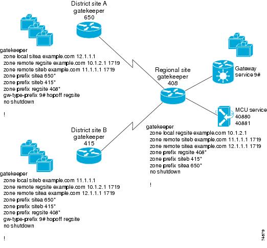
In Figure 7-2, District Site A and District Site B have hopoffs configured to forward all gateway calls (service prefix 9#) to the regional site. These hopoff statements forward calls matching 9#* to the regional site.
Figure 7-2 Inter-Zone Routing with Hopoff Statements Configured
Routing Inter-Zone Calls Using a Directory Gatekeeper
Currently, there is no gatekeeper protocol that allows gatekeepers to update each other with routing information. This limitation implies a full-mesh topology, where every gatekeeper must be statically configured to know about every other gatekeeper to which it is going to route calls. In effect, all gatekeepers must be known to each other. This poses scalability problems when a new zone or service is added because the administrator must add an entry in every gatekeeper for the new zone or service.
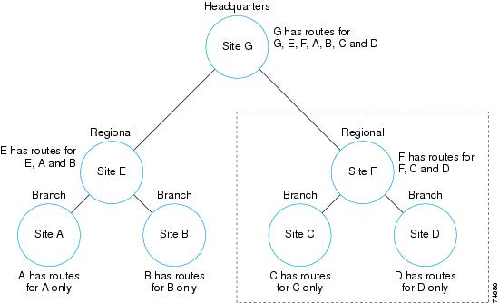
By using a directory gatekeeper and Location Request (LRQ) forwarding, a hierarchical gatekeeper design can limit the administrative overhead in a large multi-zone network. LRQ forwarding allows an administrator to create a directory gatekeeper that maintains all zone prefixes for the network or subset of the network. Call admission control is addressed by local gatekeepers, and the directory gatekeeper plays no role in it. In Figure 7-3, sites A, B, C, and D are configured to forward all LRQs that cannot be resolved locally to directory gatekeeper sites (E and F).
Figure 7-3 Inter-Zone Routing with Directory Gatekeepers
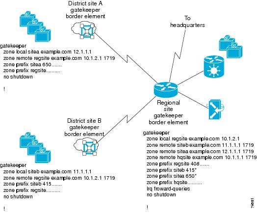
In Figure 7-4 there are three zones, two district zones and a regional zone that has a connection back to headquarters. Each district zone contains information about its local zone only. The command line zone prefix regsite .......... routes any call placed with 10 digits, but not matched in the local zone, to the regional site.
The regional site contains the routing information for its own zone as well as the two district zones associated with it. Zone prefix and hopoff statements are added to the regional site as the zones are added to the network. There is also a zone prefix hqsite .......... entry in the regional gatekeeper that forwards any 10-digit call with no match to the headquarters gatekeeper. If LRQs are going to be forwarded past the directory gatekeeper, an lrq forward-queries entry must be added to the gatekeeper, otherwise LRQs will not be forwarded past the directory gatekeeper. (LRQ forwarding has a maximum limit of seven hops.) This model can be expanded in a large network to make an H.323 network more manageable.
Figure 7-4 Directory Gatekeeper Example
Note
In Figure 7-4 the directory gatekeeper entry is zone prefix regsite .........., which allows any 10-digit dial string that is not matched locally to be forwarded to the directory gatekeeper. If there is a need for users to dial 11- or 12-digit dial strings, you can enter multiple zone prefix entries for the directory gatekeeper. Deployments that support international locations are more likely to require multiple zone prefix entries for the directory gatekeeper.
If a root zone contains a video gateway, and multiple directory gatekeeper zone prefixes are configured, you might have to add a hopoff to the configuration. If any of the directory gatekeeper zone prefix lengths match the dial string minus the service prefix, the call is forwarded to the directory gatekeeper. For example, if a local gateway service prefix is 9#, PSTN calls will be either nine digits (local calls) or 12 digits (long distance) including the service prefix.
When the gatekeeper starts to parse the dial string, it strips the service prefix and starts looking for a match. In the preceding example, local PSTN calls are parsed on seven digits and long distance PSTN calls are parsed on 11 digits. If the gatekeeper configuration contains a directory gatekeeper entry with seven dots or 11 dots, a hopoff is needed. The same rule applies to MCUs, but in most cases MCU calls are parsed on five digits or less, while most directory gatekeeper zone prefix entries are matched on 10 digits or more.
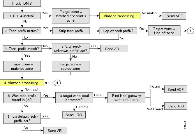
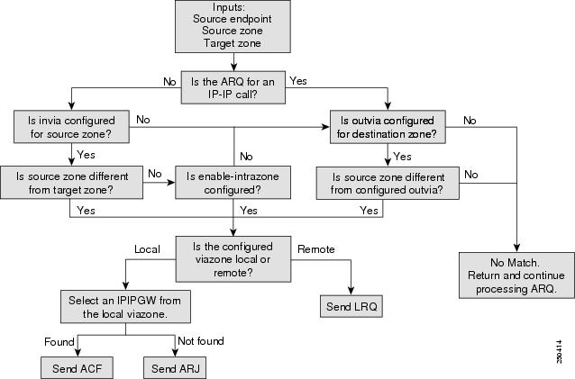
Example 7-1 illustrates the configuration of a root zone containing multiple directory gatekeeper zone prefix entries and a hopoff for 9#. The reason for the hopoff is to eliminate long distance calls (which are parsed on 11 digits) from matching the DGK zone prefix entry with 11 dots. Figure 7-5 and Figure 7-6 illustrate the parse order for Admission Requests (ARQs) and via-zone processing in the Cisco gatekeeper.
Example 7-1 Configuration of Root Zone with Multiple Director Gatekeepers
gatekeeperzone local HKG cisco.com 10.1.3.1zone remote APAC_DGK cisco.com 10.1.2.1zone prefix HKG 852.......zone prefix APAC_DGK ..........zone prefix APAC_DGK ........... (This entry matches long distance PSTN calls to a gateway)zone prefix APAC_DGK ............gw-type-prefix 9#* hopoff HKG (This entry keeps all 9# dial strings in the HGK zone)no use-proxy HKG default inbound-to terminalno use-proxy HKG default outbound-from terminalbandwidth remote 1000no shutdown
Note
Figure 7-5 Gatekeeper Address Resolution for ARQ
Figure 7-6 Via-Zone Processing
Routing Using the Border Element
Border elements can be deployed in a single gatekeeper zone or in multiple zones, as described in the following sections.
Calls with a Single Zone
Gatekeeper deployments of one local zone can have the border element inserted for all calls or for calls to and from remote zones. Although inserting border elements for all calls can have advantages, most scenarios that need border element are for isolating calls to and from remote zones.
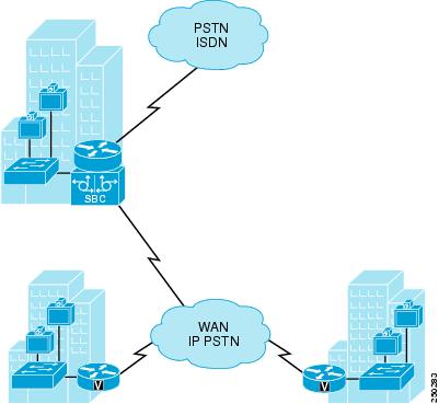
Figure 7-7 has a regional location with the gatekeeper and the border element. The local sites register the video endpoints to the gatekeeper and use gatekeeper bandwidth for call admission control. The border element is inserted into the calls for calls exiting the region to the IP PSTN, represented in the gatekeeper configuration as the remote zone. (Example 7-2 lists the configuration details.)
Figure 7-7 Single Zone for Calls
Example 7-2 Configuration of a Single Zone
dial-peer voice 1 voipdestination-pattern 91..........session target rasincoming called-number 91..........codec transparentgatekeeperzone local regsite example.com 10.1.1.1zone local vzone example.com enable-intrazonezone remote pstnzone example.com 15.1.1.1 1719 invia vzone outvia vzoneno zone subnet vzone default enablezone subnet vzone 10.1.1.1/32 enablezone prefix pstnzone 91..........no use-proxy regsite default inbound-to terminalno use-proxy regsite default outbound-from terminalno use-proxy vzone default inbound-to terminalno use-proxy vzone default outbound-from terminalno shutdown
Note
Calls with Multiple Zones
Deployments with multiple locations are more scalable with a gatekeeper and border element per location. With a border element per location, RSVP configurations are more manageable, and this also helps keep the dial plan distributed. Each gatekeeper resolves calls within its location or sends calls to other locations. The border element can be inserted into calls originated by or sent from that gatekeeper to other locations, or for calls coming into that location. For larger deployments with multiple gatekeepers, a directory gatekeeper can keep the dial plan simple.
The border element must be inserted when calls traverse the management domains or when connecting to the IP PSTN from an inside network. There would then be a single trusted device for incoming and outgoing calls through an application-aware firewall.
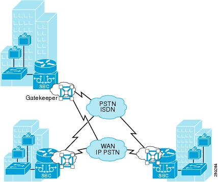
As illustrated in Figure 7-8, multiple locations can each have a border element in multiple respective zones on the gatekeeper. The respective border elements are chosen for calls to and from the locations. Media bypass can be used for intra-site calls because every call will involve the border element. (Example 7-3 lists the configuration details.)
Figure 7-8 Multiple Zones for Calls
Example 7-3 Configuration of Multiple Zones
interface FastEthernet0/0ip address 10.1.1.1 255.255.255.0h323-gateway voip interfaceh323-gateway voip id vzone ipaddr 10.1.1.1 1719h323-gateway voip h323-id regsite-cubeh323-gateway voip tech-prefix 1#h323-gateway voip bind srcaddr 10.1.1.1dial-peer voice 1000 voipdestination-pattern .Tsession target rasincoming called-number .Tcodec transparentgatekeeperzone local regsite example.com 10.1.1.1zone local vzone example.com enable-intrazonezone remote pstnzone example.com 14.1.1.1 1719 invia vzone outvia vzonezone remote vsitea example.com 11.1.1.1 1719 invia vzone outvia vzonezone remote vsiteb example.com 12.1.1.1 1719 invia vzone outvia vzoneno zone subnet regsite default enablezone subnet regsite 10.1.1.10/32 enablezone subnet regsite 10.1.1.11/32 enableno zone subnet vzone default enablezone subnet vzone 10.1.1.1/32 enablezone prefix vsitea 415.......zone prefix vsiteb 650.......gw-type-prefix 1#* default-technologyno use-proxy regsite default inbound-to terminalno use-proxy regsite default outbound-from terminalno use-proxy vzone default inbound-to terminalno use-proxy vzone default outbound-from terminalno shutdown
Note
Routing Calls to Other Networks
Calls to other unified communications network can be done using their trunk interfaces. The gatekeeper plays a key role to route calls to and from such networks. Unified communications networks can be peers or remote gatekeepers to this video network, or they can register as gateway devices to the gatekeeper. Call admission control by the gatekeeper is done using bandwidth configurations. The dial plan and call routing on the gatekeeper can be done with the zone prefix commands.
Some unified communications systems need both the signaling and media for the calls to be from a single device, or they need fixed devices to provide the call traffic. In such cases the gatekeeper can be used as the signaling entity, and the border element can do additional call signaling and media. Appropriate devices must be chosen to support the scale according to device performance and capabilities.
Routing Calls Through Untrusted Networks
When enterprises need to communicate across untrusted networks, they use firewalls as security devices to prevent unauthorized access to internal networks. Firewalls can do protocol inspection of VoIP protocols to provide a similar level of security for calls. Firewalls can inspect VoIP protocols, H.323, or SIP signaling messages and allow the appropriate traffic for the media to go between the two entities. The border element adds value here by being the one trusted device that the firewall can inspect for call signaling traffic to and from the internal network. This not only reduces the firewall configuration complexity but also allows the border element to do the topology hiding for the internal network.
Calls then can be routed through external public gatekeepers or directly to other enterprises based on the dial plan configuration. External untrusted endpoints must register with an enterprise gatekeeper so that the registration and dial plan can be managed by the enterprise. Gatekeepers then can restrict unauthorized registrations; the firewall can provide protocol inspection and security against unauthorized calls; and the border element can provide number manipulation, load balancing, call admission control, and RSVP if configured.