Downloads |
 Feedback Feedback
|
Table Of Contents
Release Notes for Cisco TV CDS 2.1.3
Configuring QoS Settings on the CDS Servers
Changing the Date and Time with NTP
Installing and Configuring the TV CDS 2.1 Software
Preparing the CDEs for the TV CDS Software
Connecting to the Serial Port on the CDE
VVI with Split-Domain Management Installation Procedure
Installing and Configuring the VVIM
Installing and Configuring the Stream Manager
Installing and Configuring the Vaults, Caching Nodes, or Streamers
Upgrading from Release 1.5.1.x
Upgrade the Software on the CDSM
Upgrade the Software on Each Streamer and Vault
Upgrading from Release 2.0 to Release 2.1.3
Getting a Software File from Cisco.com
Upgrade the Software on the CDSM
Upgrade the Software on Each Streamer and Vault
Upgrading from Release 2.1.2 to Release 2.1.3
Upgrading a VVI from Release 2.1.2 to Release 2.1.3
Getting a Software File from Cisco.com
Upgrade the Software on the CDSM
Upgrade the Software on Each Streamer and Vault
Updating the Device Drivers for new SSDs
Rolling Back the SSD Driver Update
Obtaining Documentation and Submitting a Service Request
Release Notes for Cisco TV CDS 2.1.3
These release notes cover Cisco TV CDS Release 2.1.3.
Revised: October 2011 OL-21106-02Contents
The following information is in the release notes:
•
Installing and Configuring the TV CDS 2.1 Software
•
Release 2.1.3 is a maintenance release and has no new features or enhancements.
Supported Environments
Release 2.1.3 of the Cisco TV CDS supports the following environments and associated backoffice integrations:
•
–
–
•
–
–
–
–
–
–
–
System Requirements
The Cisco TV CDS Release 2.1.3 runs on the CDE110, CDE220, and CDE420. See the Cisco Content Delivery Engine110 Hardware Installation Guide, and the Cisco Content Delivery Engine 205/220/420 Hardware Installation Guide.
The Cisco TV CDS Release 2.1.3 also runs on the CDE100, CDE200, CDE300, and CDE400 hardware models that use the Lindenhurst chipset. See the Cisco Content Delivery Engine CDE100/200/300/400 Hardware Installation Guide for set up and installation procedures.
Release 2.1.3 does not support the CDEs with the ServerWorks chipset. All CDEs with the ServerWorks chipset need to be replaced with the CDEs with the Lindenhurst chipset or the Next Generation Appliances (CDE110, CDE220, andCDE420) before upgrading to Release 2.1.3.
See the "Related Documentation" section for links to the documentation online.
Limitations and Restrictions
There are no limitations nor restrictions in Release 2.1.3.
Important Notes
The section covers the following important notes that apply to this release;
•
New SSD Driver
There is a new driver for the new solid-state drives (SSDs) that also addresses an issue with the old SSDs.
Old SSD Issue
When an abrupt power loss occurs on an older SSD while the SSD is under load, which can also happen when the SSD is being written to and a power-off shutdown occurs, the result is that the SSD may become corrupted and unusable. If an SSD becomes corrupted in this way it must be replaced.
This driver update provides a fix to prevent the corruption of the SSD when the system is being shutdown. When the system is being shutdown the driver sends a command to the SSD to stop all activity and therefore is protected from corruption.
Note
New SSDs
New solid-state drives (SSDs) used in the following CDE models require a device driver update for the TV CDS software to recognize the drives:
•
•
•
•
A new Generation 2 SSD drive could occur in one of the above newly manufactured CDEs or as a returned merchandise authorization (RMA) SSD drive replacement.
The new SSDs replace the end-of-life (EOL) external 160 GB SSDs. A new SSD drive is a Generation 2 front-mounted SSD. The new SSD model is identified by the title "Intel SSD 320 Series" on the label and has the model number: SSDSA2BW160G3. For more information, see Field Notice 63438 at: http://www.cisco.com/en/US/products/ps7126/prod_field_notices_list.html.
The new driver prevents the corruption of the existing SSDs in the field when a system is shutdown. In the case of receiving any new model of SSDs, the driver must be installed.
Note
For more information, see the "Updating the Device Drivers for new SSDs" section.
Thin Pipe Mapping
The CDSM GUI's Thin Pipe Map page allows you to configure low-bandwidth connections between local and remote groups. A local group consists of CDS servers in the same local area network (LAN). A remote group consists of all the CDS servers that are reachable by way of a wide area network (WAN).
There can be multiple thin pipes configured for each local group. As an example, a site with Caching Nodes organized into a Cache Group could have one 500-Mbps thin pipe going to a site with a Vault Group, and a second 500-Mbps thin pipe going to a location with a Stream Group. The thin pipes are completely independent of each other.
The Thin Pipe Map page also allows for the configuration of thin pipes in a hierarchy, where a remote group must be reached through several pipes. For example, a Cache Group could have a 500 Mbps thin pipe over which it streams to three Stream Groups. Each Stream Group could have separate 100 Mbps thin pipes. In this case, the Cache Group traffic on egress to all Stream Groups is limited to 500 Mbps, while ingress traffic to each Stream Group from this Cache Group is limited to 100 Mbps. In this example, the Cache Group would have four thin pipes configured: one 500 Mbps pipe to all three Stream Groups, and a total of three 100 Mbps pipes, one to each individual Stream Group.
Note
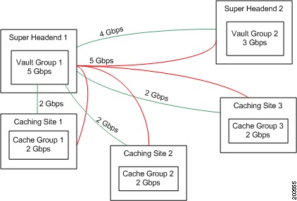
As an example, Figure 1 shows the maximum bandwidth available for the various groups in a Virtual Video Infrastructure (VVI) system with two super headends (SHEs), three caching sites, and one streaming site.
Figure 1 Thin Pipe Example
Note
Table 1 lists the thin pipe mappings that would be configured for the Vault Group 1 illustrated in Figure 1.
The thin pipes configured in Table 1 ensures that the bandwidth for Vault Group 1 never exceeds the maximum bandwidth available for Vault Group 1, which is 5 Gbps. This means that even if all remote groups were requesting cache-fills from Vault Group 1, which would be a maximum throughput of 9 Gbps, the actual maximum bandwidth of cache-fill traffic coming from Vault Group 1 would never exceed 5 Gbps.
Configuring QoS Settings on the CDS Servers
There needs to be a dedicated Differentiated Services (DiffServ) Assured Forwarding (AF) class for the CCP traffic. The Assured Forwarding PHB guarantees a certain amount of bandwidth to an AF class and allows access to extra bandwidth, if available. There are four AF classes, AF1x through AF4x. Within each class, there are three drop probabilities (low, medium, and high).
Note
Table 1 lists the DSCP parameters that are configured in the setupfile, the data types that use each parameter, and the required DSCP value for each. The DSCP value can be any number from 0 to 63, but in order for CCP traffic to work properly, the DSCP value must be one of the values listed in Table 2.
Currently, the values for the DSCP parameters must be set manually in the setupfile. Log in to each CDS server as root and edit the setupfile by adding the parameters described in Table 2. The setupfile file is located in the /arroyo/test directory.
Caution
Following are the fields that have to be added to the setupfile on each CDS server grouped by AF class. For convenience, you can copy the text of the appropriate settings for the AF class you want to use and paste it into the setupfile.
To configure for class AF1 add the following lines to the setupfile:
cache_priority0_dscp 14cache_priority1_dscp 14cache_priority2_dscp 14cache_priority3_dscp 14cache_priority4_dscp 12cache_priority5_dscp 10cache_priority6_dscp 10cache_priority7_dscp 14control_dscp 10To configure for class AF2 add the following lines to the setupfile:
cache_priority0_dscp 22cache_priority1_dscp 22cache_priority2_dscp 22cache_priority3_dscp 22cache_priority4_dscp 20cache_priority5_dscp 18cache_priority6_dscp 18cache_priority7_dscp 22control_dscp 18To configure for class AF3 add the following lines to the setupfile:
cache_priority0_dscp 30cache_priority1_dscp 30cache_priority2_dscp 30cache_priority3_dscp 30cache_priority4_dscp 28cache_priority5_dscp 26cache_priority6_dscp 26cache_priority7_dscp 30control_dscp 26To configure for class AF4 add the following lines to the setupfile:
cache_priority0_dscp 38cache_priority2_dscp 38cache_priority3_dscp 38cache_priority4_dscp 36cache_priority5_dscp 34cache_priority6_dscp 34cache_priority7_dscp 38control_dscp 34Changing the Date and Time with NTP
This section provides the details on setting the time and date. Specific NTP configuration details should be obtained from your system administrator.
The clocks on all CDS nodes (vault, streamer, cache and CDSM) in a network must be synchronized in order to retrieve the statistics on the CDSM. Synchronizing the clocks is the final step in the installation process before rebooting the system for each CDS node.
Perform the following steps to change the date and time with NTP:
Step 1
Step 2
[root@system]# chkconfig --level 2345 ntpd on[root@system]# chkconfig --list ntpdYou will see the following:
ntpd 0:off 1:off 2:on 3:on 4:on 5:on 6:offStep 3
[root@system]# service ntpd stopStep 4
[root@system]# /usr/bin/tzselectStep 5
[root@system]# date -s "16:55:30 Nov 7, 2009"Step 6
[root@system]# ntpd -q
Note
Step 7
[root@system]# service ntpd startStep 8
[root@system]# /sbin/hwclock --systohcStep 9
[root@system]# ntpq -pStep 10
[root@system]# init 6Open Caveats
This release contains the following open caveats:
CDSM
•
Symptom:
Some CDSM GUI commands are not processed properly. In this case the Reload Service Group command needs to reach the name server through DNS search.
Conditions:
If the resolv.conf file is not setup manually on the CDSM CDE100 hardware, the Reload Service Group command will not complete and streaming to service Groups could be affected.
Workaround:
Make sure DNS search is setup in resolv.conf and resubmit the Reload Service Command through the CDSM GUI.
CServer
•
Symptom:
When a vault is server off-loaded, the protocol timing log will not specifically state that the server has been off-loaded.
Conditions:
The offload functionality on vaults does not specifically notify the cache server component that it should be placed offline as its managed by the back office integration application. As a result the informational message is not displayed in the cserver logs.
Workaround:
There is no workaround for the issue.
•
Symptom:
When ingesting content with FSI ingest, there were some ingestions that failed.
Conditions:
When ingesting too many pieces of content at the same time and simultaneously capturing recordings, Linux will run out of memory and some of the ingestions will fail.
Workaround:
Reduce the number of FSI ingests that are happening at the same time.
Database
•
Symptom:
The STEAM_TRICK_REPORT.db continues to grow in file size.
Conditions:
CDS-TV 2.0.0 fc2 CDSM.
Workaround:
1.
2.
3.
4.
5.
Hardware
•
Symptom:
The internal SLC SSD Flash drives used for the Linux partitions and database are not upgradable.
Conditions:
This happens on a SSD equipped server.
Workaround:
There is no workaround for this issue. Because the drives are connected to the megaraid controller there is no direct connection for the flash process to upgrade the firmware. If the flash firmware needs to be upgraded a manual process of connecting the flash drives to the MB SATA ports must be done to upgrade the firmware. In the future, this limitation may be removed by the manufacturing of the SSD/megaraid card.
Network
•
Symptom:
NIC is abandoned when too many errors are received by an overflow condition.
Conditions:
This would typically be caused when there is not the guaranteed bandwidth required by the CDS system. This is not a common condition.
Workaround:
An internal system value can be set to prevent the overflow condition by executing the following command: echo 80000 > /proc/calypso/internal/rom_max_low_priority_rate.
RTSP
•
Symptom:
a) In specific customer integration testing, a specific backoffice sends a SETUP request for a session.
b) RTSP server is unable to send the SETUP response back to the backoffice.
Conditions:
a) Specific Customer integration testing.
b) SETUP requests coming on the backoffice port 554.
Workaround:
a) Send the SETUP requests to the set top box control port of 5554.
Vaults
•
Symptom:
Rewind tricks may appear to have regular "jitter" where a frame every so often appears out of place. On some STBs this could manifest as scrambled video frames interleaved with working ones. Other manifestations are possible. The interval should be somewhat predictable. The rate of the "jitter" should be somewhat predictable. In our case with a key change every 8 seconds in our content, and a 4X trick we saw a frame jitter about every 2 seconds. The jitter will occur DURING the playback of the trick (e.g., while rewinding), not at the start or end of the trick itself.
Conditions:
The content must be encrypted with PowerKey. It must be using keys which change on a regular basis.
Workaround:
Upgrade to a version of the code with the fix in (on the Vaults) and reingest the content (to regenerate the trick files) after you reboot.
Resolved Caveats
The following caveats have been resolved since Cisco TV CDS Release 2.1.3. Not all resolved issues are mentioned here. The following list highlights associated with customer deployment scenarios.
CDSM
•
Symptom:
Disk Stats do not get updated when a vault is in offline status.
•
Symptom:
In release 2.1 and earlier, there is a software upgrade page on CDSM. The system for maintaining the upgrade is not used and customers have requested it be removed to avoid confusion. We would like to keep the software upgrade screen in place; however, we would like to disable the upgrade downgrade image selection portion of the page as it is unused.
•
Symptom:
Extend the Content Status Report to report on damaged content. The report should take into account the complete installation to provide a an entire view if the content is damaged completely, not damaged, or may be damaged in the case of server availability problems. The solution is to have this report available in the CDSM with eventual hooks to pro actively notify a back office system of the content problem so it can be removed from the catalog and reingested.
•
Symptom:
When the Stream To Cache Map page is configured, it fails and an error message is displayed in the GUI that says, "Cannot update non-existent object: <obj name>".
Configuration
•
Symptom:
The wrong setup ID is added in the setup file when pages that modify the setup ID are submitted from the GUI.
Database
•
Symptom:
Database Crashes on VVIM.
•
Symptom:
Deleted content is successfully deleted in the cserver and database; however, in the content reports it is shown with a delete timestamp of N/A. This happens when the VVIM is down for a longer period of time, and upon restoration of the VVIM the content objects are resynchronized. It is during this resynchronization process that the delete timestamp is not populated.
Drives
•
Symptom:
Messages on the console indicate that disk drives are going off and back on line too often. The disk lights on the CDSM monitor shows this action as well. This is occurring even though the drives are not bad but only a few sectors may be.
•
Symptom:
The repair mode messages regarding disks going in and out of repair mode cause customers to think the drives are failing.
ISA
•
Symptom:
Several Vaults have the CalypsoMasterContentStore process running on them.
•
Symptom:
The stop event in the trick mode report needs to return the exact timestamp instead of rounding to the nearest second. Otherwise events might look out of order.
•
Symptom:
If the event channels are re-created after removing the Name .DB on the BMS, then CDS services (ContentStore, StreamService, LSCP/RTSP Service) do not connect to the right event channels and continue to receive the CORBA::OBJECT_NOT_EXIST exception.
Management
•
Symptom:
Master exists on a server but the UI seems inaccessible.
Network
•
Symptom:
Cache/Fill NICs on vaults show up as malfunctioning adapters in the protocoltiming logfile.
•
Symptom:
Lost packets are triggering out of capacity indicator on Content Stores, preventing delivery of Stream Request to Stream Servers, even though the Content Stores have available real capacity. We would like a tunable that would allow us to override the default settings in certain environments.
•
Symptom:
The system goes down in a rare condition if a network port is abandoned.
RTSP
•
Symptom:
In rare cases an RTSP session will hang.
Streamer
•
Cserver enhancement to accommodate a single streamer offload scenario.
•
Symptom:
After a network outage, when control primary and control backup stream servers resync, the backup primary may go into kernel debug mode if it is required to process rapid commands given from a remote control.
•
Symptom:
Macroblocking on return to 1x from a trick (fast forward, rewind or pause). Occurs about one time in sixteen.
•
Symptom:
Configure->Server Level-> RTSP Setup page shows wrong Master IP.
Vault
•
Symptom:
The Vault crashes on ingest of RTA content. It appears the RTA content consisted of NULLs at the time, then transitioned to actual frames when the signal was reacquired by the satellite.
•
Symptom:
The Vault goes into the kernel debugger when a certain file is ingested.The file is an MPEG-2 transport stream containing h.264 video. MPEG-2 video does not cause this problem.
Installing and Configuring the TV CDS 2.1 Software
This section includes the following topics:
•
•
For a CDS for an ISA environment or RTSP environment, see the software installation procedures included in the Cisco Content Delivery Engine 110 Hardware Installation Guide and the Cisco Content Delivery Engine 205/220/420 Hardware Installation Guide. See the "Related Documentation" section for information on accessing these documents.
It is a good idea to read through this entire section before performing the install or upgrade procedure.
Note
uname -r
If the response to this command has "cdstv.2.1.3.b30" in the output, the system has the TV CDS 2.1.3 software. If 2.1.3 is not on the system, see the "Getting a Software File from Cisco.com" section to obtain the TV CDS software needed for your deployment.
Release 2.1 introduces two features that require additional information when configuring the CDS servers and the CDSM:
•
•
Virtual Video Infrastructure
Release 2.1 introduces the Virtual Video Infrastructure with Caching Nodes. With the VVI, there is the option to centrally manage all the servers or to use the split-domain management. Split-domain management has two managers:
•
•
You can have multiple Stream Domains that are each managed by a separate Stream Manager. Centrally managed VVIs are only supported in an RTSP environment. A VVI in an ISA environment must use split-domain management, as well as Shared Content Store and CCP Streamers. For more information about Shared Content Store and CCP Streamers, see the Cisco TV CDS ISA 2.1 Software Configuration Guide. Each of the VVI configurations has a different installation process.
Note
CDSM Redundancy
Release 2.1 also introduces CDSM redundancy. All CDS servers keep track of both CDSM IP addresses. Each CDSM keeps track of the other CDSM IP address, as well as the virtual IP address that is used to access the CDSM. When running the cdsconfig script on each CDS server, you need to add each CDSM as a replication member. The CDSM that is chosen as the primary is accessed by using the virtual IP address. When running the cdsconfig script on each CDSM, you are prompted for the virtual IP address and subnet mask. When running the cdsconfig script on a Stream Manager, you are asked if this is the first CDSM that is getting added to the domain. For more information on the CDSM Redundancy feature, see the Cisco TV CDS ISA 2.1 Software Configuration Guide or the Cisco TV CDS RTSP 2.1 Software Configuration Guide.
Following is an overview of the procedure to add a second CDSM:
1.
2.
3.
Note
Preparing the CDEs for the TV CDS Software
Before performing the software installation and initial configuration, you must correctly install the CDEs and connect the cables as described in the Cisco Content Delivery Engine 110 Hardware Installation Guide and the Cisco Content Delivery Engine 205/220/420 Hardware Installation Guide. See the "Related Documentation" section for information on accessing these documents.
Note
Before you run the initial configuration script, you should gather the following information:
•
•
•
•
•
Note
•
Note
–
–
In both the CDS and VVI, all Vaults and Streamers are identified by an array ID, a group ID, and a server ID. In the CDSM GUI, the array ID identifies servers that are part of the same system, the group ID identifies servers that are part of the same group (Vault Group or Stream Group), and the server ID is a unique number that identifies the server. Table 1-3 lists the CDSM GUI ID names and maps them to the CServer names in the setupfile and .arroyorc files.
Connecting to the Serial Port on the CDE
The RJ-45 serial ports on the Cisco CDEs front and back panels can be used for administrative access to the CDE through a terminal server. Terminal emulation software must be configured as follows:
•
•
•
•
•
VVI with Split-Domain Management Installation Procedure
Note
The order in which you install and configure the CDEs for VVI is very important. The VVIM (Vault/Cache CDSM) and all the Vaults and Caching Nodes in the VVIM domain must be installed and configured first and brought online before the Streamer domain is configured. A high-level view of the installation order follows:
Step 1
a.
b.
Step 2
a.
b.
Note
Step 3
a.
b.
Step 4
a.
b.
Step 5
Step 6
Note
Installing and Configuring the VVIM
To install the TV CDS software and initially configure the VVIM, do the following:
Step 1
The operating system boots.
Step 2
Step 3
Step 4
[root]# ./cdsinstallThe following prompt is displayed:
Continuing first-time installation after kickstart using image //CDS-TV.iso
Select Deployment Type (ctrl-c to quit):
1) ISA2) RTSP3) CDSM4) CDSM with ISA3CDSM Selected... Output omitted ...Unmounting /mnt/cdrominst.sh completed, removing .iso image==================================================Configure the system for initial installation ==================================================Step 5
•
•
[root]# cdsconfigPlease ensure an IP address and netmask are configured formanagement interface eth0:Select an option or an interface to re-configure/disable:1. eth0 ip:172.22.97.162 mask:255.255.255.128 bcast:172.22.97.2552. Configure another interface3. DoneChoice [3]: 3Backing up old scripts in /etc/sysconfig/network-scriptsWriting new ifcfg-ethX scriptsEnter a hostname [cdsm162]: EnterEnter the number of the eth interface that connects to the gateway [0]: EnterEnter the default gateway IP address [172.22.97.129]: EnterBacking up /etc/sysconfig/networkWriting new /etc/sysconfig/networkBacking up /etc/hostsWriting new /etc/hostsRestarting network services, this may take a minute:Shutting down interface eth0: [ OK ]Shutting down loopback interface: [ OK ]Bringing up loopback interface: [ OK ]Bringing up interface eth0: [ OK ]Network services restarted; may take a few seconds to establish connectivityReboot for hostname changes to take effectNetwork configuration completePlease choose your platform from the following list of valid platforms:1. 2U-SCSI-12. 3U-SCSI-13. 3U-SCSI-104. 3U-SCSI-115. 2U-SATA-16. 2U-SATA-27. 2U-SATA-108. 2U-SATA-119. 4U-SATA-110. 4U-SATA-211. 4U-SATA-312. 4U-SATA-1013. 4U-SATA-1114. 4U-SATA-1215. CDE100-2C-116. CDE110-2C-1Choice: 16Please select a role for this CDSM:1. CDS Manager (single domain)2. VVI Manager (split domain for Vault and Caching node)3. CDS Manager (split domain for Streamers)Choice: 2Please enter a group ID: 12345Please enter a server ID [62]: 162Writing new configuration to /home/isa/.arroyorcNo existing replication group information foundDo you want to configure replication group members now? (yes/no) [y]: yThere are currently no replication group members.Do you want to add another replication group member? (yes/no) [y]: y
Note
In the following example, the configuration of the CDS devices shows generalized input values. Option 5, cdsmgw, is the Stream Manager. Add the Stream Manager as a replication group member.
Select a role for the new replication group member:1. ssv2. Vault3. cache4. Streamer5. cdsmgwChoice: device_role (1, 2, 3, 4, 5 or 6)Enter an IP address for new CDS_device: IP_AddressCurrent replication group members:device_role IP_AddressDo you want to add another replication group member? (yes/no) [n]: nConfiguring CDSMDatabase is running.Do you want to enable CDSM Redundancy ? (yes/no) [y]:CDSM Virtual IP [172.22.99.106]:Subnet Mask [255.255.254.0]:Writing rc.localCDSM configuration finishedcdsconfig finished, please use CDSM to complete configuration[root]#Step 6
dbdomsock /tmp/isadb
If the preceding line is not in the file, use a text editor to add the line. Close and save the .arroyorc file.
Step 7
[root]# su - isa //==== start avsdb[isa]$ pgrep avsdb28794 //==== verify avsdb process is running[isa]$ exitlogout[root]# /arroyo/www/bin/apachectl start //==== start apache serverhttpd: Could not reliably determine the server's fully qualified domain name, using 172.22.97.162 for ServerName[root]#Step 8
http://VVIM_ip_addressThe VVIM Login page is displayed.
Step 9
If you are unable to log in with the username admin and the password admin, do the following:
a.
[root]#/home/stats/runonceb.
The VVIM Setup page is displayed.
Step 10
•
•
Once the VVIM has been installed and initially configured, install and initially configure the Vaults and Caching Nodes that are part of this VVIM domain. See the "Installing and Configuring the Vaults, Caching Nodes, or Streamers" section for more information. When all the servers in the VVIM domain have been configured and are listed on the VVIM's System Health Monitor page, install and configure the Stream Manager. See the "Installing and Configuring the Stream Manager" section for more information.
Installing and Configuring the Stream Manager
To install the TV CDS software and initially configure the Stream Manager, do the following:
Step 1
The operating system boots.
Step 2
Step 3
Step 4
[root]# ./cdsinstallThe following prompt is displayed:
Continuing first-time installation after kickstart using image //CDS-TV.iso
Select Deployment Type (ctrl-c to quit):
1) ISA2) RTSP3) CDSM4) CDSM with ISA3CDSM Selected... Output omitted ...Unmounting /mnt/cdrominst.sh completed, removing .iso image==================================================Configure the system for initial installation ==================================================Step 5
•
•
[root]# cdsconfigPlease ensure an IP address and netmask are configured formanagement interface eth0:Select an option or an interface to re-configure/disable:1. eth0 ip:172.22.97.162 mask:255.255.255.128 bcast:172.22.97.2552. Configure another interface3. DoneChoice [3]: 3Backing up old scripts in /etc/sysconfig/network-scriptsWriting new ifcfg-ethX scriptsEnter a hostname [cdsm162]: EnterEnter the number of the eth interface that connects to the gateway [0]: EnterEnter the default gateway IP address [172.22.97.129]: EnterBacking up /etc/sysconfig/networkWriting new /etc/sysconfig/networkBacking up /etc/hostsWriting new /etc/hostsRestarting network services, this may take a minute:Shutting down interface eth0: [ OK ]Shutting down loopback interface: [ OK ]Bringing up loopback interface: [ OK ]Bringing up interface eth0: [ OK ]Network services restarted; may take a few seconds to establish connectivityReboot for hostname changes to take effectNetwork configuration completePlease choose your platform from the following list of valid platforms:1. 2U-SCSI-12. 3U-SCSI-13. 3U-SCSI-104. 3U-SCSI-115. 2U-SATA-16. 2U-SATA-27. 2U-SATA-108. 2U-SATA-119. 4U-SATA-110. 4U-SATA-211. 4U-SATA-312. 4U-SATA-1013. 4U-SATA-1114. 4U-SATA-1215. CDE100-2C-116. CDE110-2C-1Choice: 16Please select a role for this CDSM:1. CDS Manager (single domain)2. VVI Manager (split domain for Vault and Caching node)3. CDS Manager (split domain for Streamers)Choice: 3Is this Streaming Domain going to use CCP as Cache Fill Protocol? (yes/no) [y]: YIs this the first CDS Manager getting added to this domain? (yes/no) [y]:Enter the name of this Stream Domain: StreamDomain1Enter the IP address of the VVIM: 172.22.99.109Retrieved Server ID '1001' from '172.22.99.109'Please enter a group ID: 12345
Note
Writing new configuration to /home/isa/.arroyorcNo existing replication group information foundDo you want to configure replication group members now? (yes/no) [y]: yThere are currently no replication group members.Do you want to add another replication group member? (yes/no) [y]: y
Note
In the following example, the configuration of the CDS devices shows generalized input values. Option 5, vvimgw, is the VVIM. Add the VVIM as a replication group member.
Note
1. ssv2. Vault3. cache4. Streamer5. vvimgwChoice: device_role (1, 2, 3, 4, 5 or 6)Enter an IP address for new CDS_device: IP_AddressCurrent replication group members:device_role IP_AddressDo you want to add another replication group member? (yes/no) [n]: nConfiguring CDSMDatabase is running.Do you want to enable CDSM Redundancy ? (yes/no) [y]:CDSM Virtual IP [172.22.99.106]:Subnet Mask [255.255.254.0]:Writing rc.localCDSM configuration finishedcdsconfig finished, please use CDSM to complete configuration[root]#Step 6
dbdomsock /tmp/isadb
If the preceding line is not in the file, use a text editor to add the line. Close and save the .arroyorc file.
Step 7
[root]# su - isa //==== start avsdb[isa]$ pgrep avsdb28794 //==== verify avsdb process is running[isa]$ exitlogout[root]# /arroyo/www/bin/apachectl start //==== start apache serverhttpd: Could not reliably determine the server's fully qualified domain name, using 172.22.97.162 for ServerName[root]#Step 8
http://Stream_Manager_ip_addressThe Stream Manager Login page is displayed.
Step 9
If you are unable to log in with the username admin and the password admin, do the following:
a.
[root]#/home/stats/runonceb.
The CDSM Setup page is displayed.
Step 10
•
•
Installing and Configuring the Vaults, Caching Nodes, or Streamers
To install the TV CDS software and initially configure each Vault, Caching Node, or Streamer, do the following:
Step 1
Step 2
So that your password for root is not the default password, use the passwd command to change the password used.
Step 3
[root]# ./cdsinstallYou should see something similar to this:
Continuing first-time installation after kickstart using image //CDS-TV.isoSelect Deployment Type (ctrl-c to quit):1) ISA2) RTSP/FSI3) CDSM4) CDSM with ISA1ISA SelectedMounting //CDS-TV.iso at /mnt/cdromCalling inst.sh for isaKilling running processes: statsdUn-taring isa-base.tgzCalling forprod.shRemoving RTSP-specific filesInstalling ISA-specific files (existing files backed up to .file)ISA installation completeStarting fixperms.shLoading File ListProcessing File ListEnding fixperms.shUnmounting /mnt/cdrominst.sh completed, removing .iso imageStep 4
[root]# ./cdsinstall CDS-TV-2.1.3.isoYou must reboot the system after running the install script. When the system has rebooted, login as root and continue with Step 5.
Step 5
[root]# cdsconfigYou should see something similar to this:
Please ensure an IP address and netmask are configured formanagement interface eth0:Select an option or an interface to re-configure/disable:1. eth0 ip:172.22.99.237 mask:255.255.254.0 bcast:172.22.99.2552. Configure another interface3. DoneChoice [3]:Step 6
Step 7
Step 8
Step 9
Step 10
Select an option or an interface to re-configure/disable:1. eth0 ip:172.22.99.238 mask:255.255.254.0 bcast:172.22.99.2552. Configure another interface3. DoneChoice [3]:Step 11
Backing up old scripts in /etc/sysconfig/network-scriptsWriting new ifcfg-ethX scriptsStep 12
Step 13
Step 14
Backing up /etc/sysconfig/networkWriting new /etc/sysconfig/networkBacking up /etc/hostsWriting new /etc/hostsShutting down interface eth0: [ OK ]Shutting down loopback interface: [ OK ]PCI: Enabling device 0000:0e:00.0 (0000 -> 0003)PCI: Enabling device 0000:0e:00.1 (0000 -> 0003)Restarting network services, this may take a minute:Shutting down loopback interface: [ OK ]Bringing up loopback interface: [ OK ]Bringing up interface eth0: [ OK ]Network services restarted; may take a few seconds to establish connectivityReboot for hostname changes to take effectNetwork configuration completeUse detected platform: CDE420-4A-C ? (yes/no) [y]: yUse detected platform: CDE420-4A-C ? (yes/no) [y]: yStep 15
Please select a device role:1. ssv2. Vault3. cache4. StreamerStep 16
Step 17
Step 18
Enter Stream Control interface (Hit 'Enter' to skip): eth1Writing new configuration to /home/isa/.arroyorcNo existing replication group information foundDo you want to configure replication group members now? (yes/no) [y]: yesThere are currently no replication group members.Do you want to add another replication group member? (yes/no) [y]: y
Note
In the following example, the configuration of the CDS devices shows generalized input values. The option for the VVIM and Stream Manager is called "Controller." Add the VVIM and Stream Manager as a replication group members, as well as the Vaults, Caching Nodes, and Streamers.
Select a role for the new replication group member:1. ssv2. Vault3. cache4. Streamer5. ControllerStep 19
Step 20
Current replication group members:Vault 172.22.99.239Do you want to add another replication group member? (yes/no) [n]:Step 21
Configuring ISA ecosystem/home/isa/Berkeley/status_db:dbstatus: Subscript out of range.Starting statsdRun svrinit to seed database? (yes/no) [n]: yStep 22
Note
a.
b.
c.
Writing rc.localISA ecosystem configuration finishedcdsconfig finished, please use CDSM to complete configuration[root@v238 ~]#If you receive an error message saying the database is unavailable and cannot set things up, enter the following command to initialize the database tables:
[root]# su - isa (For ISA deployments only.)[isa]# exit[root]# /home/stats/svrinit_15 -h <hostname> -i <ip address> -s <mask-ip address>
Note
Note
Step 23
a.
http://XXX.XXX.XXX.XXXThe VVIM or CDSM Login page is displayed.
b.
The System Health Monitor page is displayed showing the devices and their IP address.
The TV CDS software installation is complete.
Upgrading to Release 2.1
This section includes the following topics:
•
•
•
•
Note
Release 2.1 introduces the ability to route interfaces to different subnets. After upgrading the TV CDS software to Release 2.1, any servers with incompatible routes are listed in red on the Route Tables page. You can review the Route Table configuration for each of these servers, modify or delete the routes, and click Submit to apply the changes. The routes are converted to the Release 2.1 format and the server is listed in black. When all servers with incompatible routes are fixed, the warning message is removed and the entry in the system alarm drop-down list in the GUI banner is removed.
Release 2.1 also introduces the ability to configure up to 16 DNS servers on each of the System Level, Array Level, and Server Level DNS pages. After upgrading the TV CDS software to Release 2.1, any DNS entries need to be resubmitted. When all DNS entries are resubmitted, the warning message is removed and the entry in the system alarm drop-down list in the GUI banner is removed.
Note
Note
A high-level view of the CDS software upgrade procedure is as follows:
1.
2.
Repeat for every Streamer on the site starting with the "Available" Streamers, followed by the "Backup" Streamer, and ending with the "Primary" Streamer.
3.
Caution
Note
Upgrading from Release 1.5.1.x
Note
The Cisco technician will have the following items to upgrade your software to Release 2.1:
•
•
•
•
•
•
•
Note
Upgrade the Software on the CDSM
Upgrading the software on the CDSM has the following main tasks:
1.
2.
3.
4.
5.
6.
7.
8.
9.
Upgrade the Software on Each Streamer and Vault
Note
In a multi-site CDS, upgrade all the Vaults using the same procedural order as the Streamers (offload, upgrade, reboot, and online). Start the Vault upgrade at the Control sites, then finish with the Setup/Control site.
Note
For Vaults:
•
For Streamers:
•
•
Upgrading the software on a Streamer or a Vault has the following main tasks:
1.
2.
3.
4.
5.
6.
7.
8.
Upgrading from Release 2.0 to Release 2.1.3
Upgrading the CDSM and CDS servers from Release 2.0 to Release 2.1.3 involves the following steps:
1.
2.
3.
4.
5.
Note
After upgrading the TV CDS software to Release 2.1, any servers with incompatible routes are listed in red on the Route Tables page. You can review the Route Table configuration for each of these servers, modify or delete the routes using the information you recorded, and click Submit to apply the changes. For more information, see either the Cisco TV CDS 2.1 ISA Software Configuration Guide or the Cisco TV CDS 2.1 RTSP Software Configuration Guide.
The following procedures are covered in this section:
•
•
•
Getting a Software File from Cisco.com
To get a software file from Cisco.com, do the following:
Step 1
http://tools.cisco.com/support/downloads/go/Redirect.x?mdfid=268438145
The Log In page is displayed.
Step 2
Step 3
Step 4
Step 5
Step 6
•
•
The Download page is displayed with the information about the software image file and a Download link.
Step 7
Step 8
Step 9
Step 10
Upgrade the Software on the CDSM
Note
To upgrade the software on the CDSM, do the following:
Step 1
Step 2
# scp 172.22.98.111:/images/2.1/CDS-TV-2.1.3.iso /rootStep 3
# scp 172.22.98.111:/images/2.1/cdsinstall /rootStep 4
# ./cdsinstall CDS-TV-2.1.3.isoSelect Deployment Type (ctrl-c to quit):1) ISA2) RTSP/FSI3) CDSM4) CDSM with ISA--- Output omitted ---Step 5
# rebootStep 6
ps -ef | grep avsdb
Upgrade the Software on Each Streamer and Vault
Perform this procedure for each Vault and Streamer in the CDS.
Note
In a multi-site CDS, upgrade all the Vaults using the same procedural order as the Streamers (offload, upgrade, reboot, and online). Start the Vault upgrade at the Control sites, then finish with the Setup/Control site.
To upgrade the software on a Vault or Streamer, do the following:
Step 1
a.
b.
c.
Step 2
a.
b.
c.
Step 3
Step 4
# scp 172.22.98.111:/images/2.1/CDS-TV-2.1.3.iso /rootStep 5
# scp 172.22.98.111:/images/2.1/cdsinstall /rootStep 6
# ./cdsinstall CDS-TV-2.1.3.isoSelect Deployment Type (ctrl-c to quit):1) ISA2) RTSP/FSI3) CDSM4) CDSM with ISA--- Output omitted ---Step 7
a.
b.
c.
Step 8
a.
b.
Step 9
a.
b.
c.
Step 10
Upgrading from Release 2.1.2 to Release 2.1.3
Note
Upgrading the CDSM and CDS servers from Release 2.1.2 to Release 2.1.3 involves the following steps:
1.
2.
3.
4.
5.
The following procedures are covered in this section:
•
•
•
Upgrading a VVI from Release 2.1.2 to Release 2.1.3
A high-level view of the VVI software upgrade procedure is as follows:
1.
2.
[isa@vault220 ~/IntegrationTest]$ ./show_calypso_services********************************************************************** ContentStore (SLAVE) Services Status ************************************************************************ContentStoreSlave ======> Running************************************************************************************************************************************************************************************Follow the "Upgrade the Software on Each Streamer and Vault" procedure. When all SHEs are upgraded, there will be Vaults running Release 2.1.3 coexisting with Caching Nodes and Streamers running Release 2.1.2.
3.
a.
b.
c.
d.
[root@s65 root]# cat /proc/calypso/status/streamer/resiliencyinfoStreamer Resiliency Info:Service Address: 172.22.98.50Control Service: Primary
Note
Getting a Software File from Cisco.com
To get a software file from Cisco.com, do the following:
Step 1
http://tools.cisco.com/support/downloads/go/Redirect.x?mdfid=268438145
The Log In page is displayed.
Step 2
Step 3
Step 4
Step 5
Step 6
•
•
The Download page is displayed with the information about the software image file and a Download link.
Step 7
Step 8
Step 9
Step 10
Upgrade the Software on the CDSM
Note
To upgrade the software on the CDSM, do the following:
Step 1
Step 2
# scp 172.22.98.111:/images/2.1/CDS-TV-2.1.3.iso /rootStep 3
# scp 172.22.98.111:/images/2.1/cdsinstall /rootStep 4
# ./cdsinstall CDS-TV-2.1.3.isoSelect Deployment Type (ctrl-c to quit):1) ISA2) RTSP/FSI3) CDSM4) CDSM with ISA--- Output omitted ---Step 5
# rebootStep 6
ps -ef | grep avsdb
Upgrade the Software on Each Streamer and Vault
Perform this procedure for each Vault and Streamer in the CDS.
Note
In a multi-site CDS, upgrade all the Vaults using the same procedural order as the Streamers (offload, upgrade, reboot, and online). Start the Vault upgrade at the Control sites, then finish with the Setup/Control site.
To upgrade the software on a Vault or Streamer, do the following:
Step 1
a.
b.
c.
Step 2
a.
b.
c.
Step 3
Step 4
# scp 172.22.98.111:/images/2.1/CDS-TV-2.1.3.iso /rootStep 5
# scp 172.22.98.111:/images/2.1/cdsinstall /rootStep 6
# ./cdsinstall CDS-TV-2.1.3.isoSelect Deployment Type (ctrl-c to quit):1) ISA2) RTSP/FSI3) CDSM4) CDSM with ISA--- Output omitted ---Step 7
a.
b.
c.
Step 8
a.
b.
Step 9
a.
b.
c.
Step 10
Adding a Second CDSM
To implement the CDSM Redundancy feature available in Release 2.1, do the following after upgrading all existing servers to Release 2.1:
Step 1
The operating system boots.
Step 2
Note
Step 3
[root]# ./cdsinstallThe following prompt is displayed:
Continuing first-time installation after kickstart using image //CDS-TV.iso
Select Deployment Type (ctrl-c to quit):
1) ISA2) RTSP3) CDSM4) CDSM with ISA3CDSM Selected... Output omitted ...Unmounting /mnt/cdrominst.sh completed, removing .iso image==================================================Configure the system for initial installation ==================================================Step 4
# scp -r 172.22.98.109:/arroyo/db/DATADIR /arroyo/dbStep 5
For more detail about the cdsconfig script, see the "Installing and Configuring the Stream Manager" section.
Step 6
# vi /etc/rc.local#!/bin/sh## This script will be executed *after* all the other init scripts.# You can put your own initialization stuff in here if you don't# want to do the full Sys V style init stuff.touch /var/lock/subsys/local# Lines below this one modified by cdsflavconfig (ISA):su - isa -c "cd /home/isa/IntegrationTest"sleep 30/arroyo/www/bin/apachectl startsleep 30su - isa -c "cd /home/isa/RTScheduler/Exporter; ./ExporterServer >& /home/isa/RTScheduler/Exporter/ExporterServer.log&"/home/stats/statsd -i 172.11.99.100 -s 255.255.255.0 -d eth0sleep 30Step 7
# rebootStep 8
a.
b.
$ vi /home/isa/.arroyorc# Local settingsself 2groupid 400serverid 141partno 3U-SCSI-10mirroring 0mgmtif 0ingestif 1# Database Paramsdbdomsock /tmp/isadbdbnetport 9999# Replication Group MembersVault 111.0.110.40controller 111.0.110.42c.
[root]# su - isa (For ISA deployments only.)[isa]# exit[root]# /home/stats/svrinit_15 -h <hostname> -i <ip address> -s <mask-ip address>
Note
Updating the Device Drivers for new SSDs
The SSD driver update is for new SSDs and to address an issue with older SSDs. For more information, see the "Important Notes" section.
If a CDE requires an SSD replacement, the device driver must be updated. The device driver must be updated before replacing the SSD. If a new CDE is being added to the CDS, after upgrading the TV CDS software, the device driver must be updated. New SSDs are not recognized with the proper attributes until the device driver is updated.
Note
To view a list of TV CDS software releases this device driver applies to see the defect, CSCtr29064, in the Bug Tool Kit ((http://tools.cisco.com/Support/BugToolKit/).
Note
To install the device driver update package, do the following:
Step 1
Note
Following is the md5 checksum for the cdstv_x.y.z_CSCtr29064.bin driver update package:
89684e2094d841b236ba1d83e958df9b cdstv_x.y.z_CSCtr29064.binThe driver update package is a self-extracting, self-installing package.
Step 2
# chmod 755 /root/cdstv_x.y.z_CSCtr29064.binStep 3
# cd /root# ./cdstv_x.y.z_CSCtr29064.binThe package installs the device driver.
Step 4
Step 5
cd /lib/module/`uname -r`/sbin/modinfo -F version csd.ko cdd_sys.koThe updated driver files report the same version for both driver files in the format of x.y.z.1, where x.y.z is the version of the TV CDS software (for example, 2.3.3.1).
Step 6
# reboot
Note
A new SSD drive is a Generation 2 front-mounted SSD. The new SSD model is identified by the title "Intel SSD 320 Series" on the label and has the model number: SSDSA2BW160G3. For more information, see Field Notice 63438 at: http://www.cisco.com/en/US/products/ps7126/prod_field_notices_list.html.
The following command provides information on the external SSDs that are the new drive model:
# find /sys/devices -name "model" | xargs grep SSDSA2BW16/sys/devices/pci0000:80/0000:80:05.0/0000:87:00.0/host3/port-3:7/end_device-3:7/target3:0:7/3:0:7:0/model:INTEL SSDSA2BW16/sys/devices/pci0000:80/0000:80:05.0/0000:87:00.0/host3/port-3:6/end_device-3:6/target3:0:6/3:0:6:0/model:INTEL SSDSA2BW16/sys/devices/pci0000:80/0000:80:05.0/0000:87:00.0/host3/port-3:5/end_device-3:5/target3:0:5/3:0:5:0/model:INTEL SSDSA2BW16/sys/devices/pci0000:80/0000:80:05.0/0000:87:00.0/host3/port-3:4/end_device-3:4/target3:0:4/3:0:4:0/model:INTEL SSDSA2BW16/sys/devices/pci0000:80/0000:80:05.0/0000:87:00.0/host3/port-3:3/end_device-3:3/target3:0:3/3:0:3:0/model:INTEL SSDSA2BW16To view all SSD models currently supported by the Cisco TV CDS software, enter the following command:
# find /sys/devices -name "model" | xargs grep SSDSAThe older SSD model is INTEL SSDSA2M160.
Rolling Back the SSD Driver Update
If for any reason you need to revert to the older SSD driver, with the TV CDS software running on the CDS server, do the following:
Step 1
cd /lib/module/`uname -r`Step 2
cp csd.ko csd.ko.updatecp cdd_sys.ko cdd_sys.ko.updateStep 3
cp csd.ko_bkup_<previous_version> csd.kocp cdd_sys.ko_bkup_<previous_version> cdd_sys.koStep 4
/sbin/modinfo -F version csd.ko cdd_sys.koThe drivers before the driver update have a version in the format of a.b.c and the two drivers do not necessarily have the same version number.
Step 5
Related Documentation
Refer to the following documents for additional information about the Cisco TV CDS 2.1:
•
•
•
http://www.cisco.com/en/US/docs/video/cds/cda/tv/2_1/developer_guide/tv_cds_2_1_apiguide.html
•
http://www.cisco.com/en/US/docs/video/cds/overview/CDS_Roadmap.html
•
•
http://www.cisco.com/en/US/docs/video/cds/cde/cde110/installation/guide/cde110_install.html
•
http://www.cisco.com/en/US/docs/video/cds/cde/installation/guide/CDE_Install_Book.html
•
http://www.cisco.com/en/US/docs/video/cds/cde/regulatory/compliance/CDE_RCSI.html
The entire CDS software documentation suite is available on Cisco.com at:
http://www.cisco.com/en/US/products/ps7127/tsd_products_support_series_home.html
The entire CDS hardware documentation suite is available on Cisco.com at:
http://www.cisco.com/en/US/products/ps7126/tsd_products_support_series_home.html
Obtaining Documentation and Submitting a Service Request
For information on obtaining documentation, submitting a service request, and gathering additional information, see the monthly What's New in Cisco Product Documentation, which also lists all new and revised Cisco technical documentation, at:
http://www.cisco.com/en/US/docs/general/whatsnew/whatsnew.html
Subscribe to the What's New in Cisco Product Documentation as a Really Simple Syndication (RSS) feed and set content to be delivered directly to your desktop using a reader application. The RSS feeds are a free service and Cisco currently supports RSS version 2.0.
CCDE, CCENT, CCSI, Cisco Eos, Cisco Explorer, Cisco HealthPresence, Cisco IronPort, the Cisco logo, Cisco Nurse Connect, Cisco Pulse, Cisco and the Cisco Logo are trademarks of Cisco Systems, Inc. and/or its affiliates in the U.S. and other countries. A listing of Cisco's trademarks can be found at www.cisco.com/go/trademarks. Third party trademarks mentioned are the property of their respective owners. The use of the word partner does not imply a partnership relationship between Cisco and any other company. (1005R)
Any Internet Protocol (IP) addresses used in this document are not intended to be actual addresses. Any examples, command display output, and figures included in the document are shown for illustrative purposes only. Any use of actual IP addresses in illustrative content is unintentional and coincidental.
© 2011 Cisco Systems, Inc. All rights reserved.