-
Cisco UCS Manager B-Series Troubleshooting Guide
-
Preface
-
Overview of Troubleshooting in Cisco UCS Manager
-
Finite State Machine
-
General Troubleshooting Solutions
-
Troubleshooting Issues with Cisco UCS Manager
-
Troubleshooting Server Disk Drive Detection and Monitoring
-
Troubleshooting SAN Boot and SAN Connectivity Issues
-
Troubleshooting Server Hardware Issues
-
Index
-
 Feedback
Contents
- Troubleshooting Server Hardware Issues
- Diagnostics Button and LEDs
- DIMM Memory Issues
- Known DIMM Memory Issues
- Cisco UCS Manager GUI Incorrectly Reports Bad DIMMs
- Resetting the BMC to Clear DIMM Error
- Cisco UCS Manager Incorrect Report of Effective Memory
- Memory Misreported in Cisco UCS Manager
- Single DIMM Causes Other DIMMs To Get Marked as Bad and POST Fails
- Troubleshooting DIMM Errors
- Correct Installation of DIMMs
- Troubleshooting DIMM Errors Using the Cisco UCS Manager CLI
- Troubleshooting DIMM Errors Using the Cisco UCS Manager GUI
- Troubleshooting Degraded DIMM Errors
- Troubleshooting Inoperable DIMMs Errors
- Recommended Solutions for DIMM Issues
- CPU Issues
- Troubleshooting CPU Issues Using the CLI
- Troubleshooting CPU Issues Using the GUI
- Recommended Solutions for CPU Issues
- CPU CATERR Details
- Disk Drive and RAID Issues
- RAID Controllers
- Disabling Quiet Boot
- Accessing ROM-Based Controller Utilities
- Documentation About RAID Controllers and LSI Utilities
- Moving a RAID Cluster Using UCS Software Version 1.4(1)
- Moving a RAID Cluster Using UCS Software Version 1.4(2) and Forward
- Moving a RAID Cluster Between B200 M3 Servers
- Replacing a Failed Drive in a RAID Cluster
- Adapter Issues
- Known Adapter Issues
- Troubleshooting Adapter Errors Using the CLI
- Troubleshooting Adapter Errors Using the GUI
- Recommended Solutions for Adapter Issues
- Power Issues
- Troubleshooting a FET Failure in a Cisco UCS B440 Server
- Information Needed Before Calling Cisco TAC
- Related B-Series Server Documentation
Troubleshooting Server Hardware Issues
This chapter includes the following sections:
- Diagnostics Button and LEDs
- DIMM Memory Issues
- CPU Issues
- Disk Drive and RAID Issues
- Adapter Issues
- Power Issues
- Information Needed Before Calling Cisco TAC
- Related B-Series Server Documentation
Diagnostics Button and LEDs
At the blade start-up, the POST diagnostics test the CPUs, DIMMs, HDDs, and adapter cards. Any failure notifications are sent to Cisco UCS Manager. You can view these notification in the system error log (SEL) or in the output of the show tech-support command. If errors are found, an amber diagnostic LED lights up next to the failed component. During run time, the blade BIOS, component drivers, and OS monitor for hardware faults. The amber diagnostic LED lights up for any component if an uncorrectable error or correctable errors (such as a host ECC error) over the allowed threshold occurs.
The LED states are saved. If you remove the blade from the chassis, the LED values persist for up to 10 minutes. Pressing the LED diagnostics button on the motherboard causes the LEDs that currently show a component fault to light up for up to 30 seconds. The LED fault values are reset when the blade is reinserted into the chassis and booted.
If any DIMM insertion errors are detected, they can cause the blade discovery to fail and errors are reported in the server POST information. You can view these errors in either the Cisco UCS Manager CLI or the Cisco UCS Manager GUI. The blade servers require specific rules to be followed when populating DIMMs in a blade server. The rules depend on the blade server model. Refer to the documentation for a specific blade server for those rules.
The HDD status LEDs are on the front of the HDD. Faults on the CPU, DIMMs, or adapter cards also cause the server health LED to light up as a solid amber for minor error conditions or blinking amber for critical error conditions.
DIMM Memory Issues
A problem with the DIMM memory can cause a server to fail to boot or cause the server to run below its capabilities. If DIMM issues are suspected, consider the following:
- DIMMs tested, qualified, and sold by Cisco are the only DIMMs supported on your system. Third-party DIMMs are not supported, and if they are present, Cisco technical support will ask you to replace them with Cisco DIMMs before continuing to troubleshoot a problem.
- Check if the malfunctioning DIMM is supported on that model of server. Refer to the server’s installation and service notes to verify whether you are using the correct combination of server, CPU and DIMMs.
- Check if the malfunctioning DIMM seated correctly in the slot. Remove and reseat the DIMMs.
- All Cisco servers have either a required or recommended order for installing DIMMs. Refer to the server’s installation and service notes to verify that you are adding the DIMMs appropriately for a given server type.
- Most DIMMs are sold in matched pairs. They are intended to be added two at a time, paired with each other. Splitting the pairs can cause memory problems.
- If the replacement DIMMs have a maximum speed lower than those previously installed, all DIMMs in a server run at the slower speed or not work at all. All of the DIMMs in a server should be of the same type.
- The number and size of DIMMs should be the same for all CPUs in a server. Mismatching DIMM configurations can damage system performance.
Known DIMM Memory Issues
Cisco UCS Manager GUI Incorrectly Reports Bad DIMMs
The Cisco UCS Manager GUI can incorrectly report “inoperable memory” when the Cisco UCS Manager CLI indicates no failures. This problem has occurred when running Cisco UCS Manager, Release1.0(1e).
Upgrade to Cisco UCS Manager, Release1.0(2d) or a later release. If that is not possible, to confirm memory is OK, enter the following CLI commands in order (where x=chassis# and y=server# and z=memory array ID#):
Resetting the BMC to Clear DIMM Error
ProcedureCorrectable DIMM errors report a DIMM as “Degraded” in Cisco UCS Manager, but the DIMMs are still available to the OS on the blade.
To correct this problem, use the following commands to clear the SEL logs from the BMC, then reboot the BMC of the affected blade, or just remove and reseat the blade server from the chassis.
Command or Action Purpose Cisco UCS Manager Incorrect Report of Effective Memory
When running Cisco UCS Manager, Release 1.0(1e), Cisco UCS Manager can misread the SMBIOS table, and not be able to read it without a server reboot.
Upgrade to Cisco UCS Manager, Release 1.2(0) or a later release.
Memory Misreported in Cisco UCS Manager
Memory arrays show more memory sockets than are physically on the system board.
Upgrade to Cisco UCS Manager, release 1.0(2j) or later.
Single DIMM Causes Other DIMMs To Get Marked as Bad and POST Fails
The server does not complete its boot cycle, and the FSM remains stuck at 54 percent.
Upgrade to Cisco UCS Manager, Release 1.2.(1b) or a later release.
Troubleshooting DIMM Errors
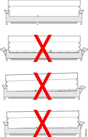
Correct Installation of DIMMs
Verify that the DIMMs are installed correctly.
In the first example in the following figure, a DIMM is correctly inserted and latched. Unless there is a small bit of dust blocking one of the contacts, this DIMM should function correctly. The second example shows a DIMM that is mismatched with the key for its slot. That DIMM cannot be inserted in this orientation and must be rotated to fit into the slot. In the third example, the left side of the DIMM seems to be correctly seated and the latch is fully connected, but the right side is just barely touching the slot and the latch is not seated into the notch on the DIMM. In the fourth example, the left side is again fully inserted and seated, and the right side is partially inserted and incompletely latched.
Troubleshooting DIMM Errors Using the Cisco UCS Manager CLI
ProcedureThe following example shows how to check memory information using the Cisco UCS Manager CLI:
UCS-A# scope server 1/5
UCS-A /chassis/server # show memory detail
Server 1/5:
    Array 1:
        CPU ID: 1
        Current Capacity (GB): 393216
        Error Correction: Undisc
        Max Capacity (GB): 393216
        Max Devices: 48
        Populated: 48

        DIMMS:

        ID 1:
            Location: DIMM_A0
            Presence: Equipped
            Overall Status: Operable
            Operability: Operable
            Visibility: Yes
            Product Name: 8GB DDR3-1333MHz RDIMM/PC3-10600/dual rank 2Gb DRAM
            PID: N01-M308GB2
            VID: V01
            Vendor: 0xCE00
            Vendor Description: Samsung Electronics, Inc.
            Vendor Part Number: M393B1K70BH1-CH9
            Vendor Serial (SN): 0x46185EC2
            HW Revision: 0
            Form Factor: Dimm
            Type: Other
            Capacity (MB): 8192
            Clock: 1067
            Latency: 0.900000
            Width: 64
.
.
.
UCS-A /chassis/server # show memory-array detail

Memory Array:
    ID: 1
    Current Capacity (GB): 384
    Max Capacity (GB): 384
    Populated: 48
    Max Devices: 48
    Error Correction: Undisc
    Product Name:
    PID:
    VID:
    Vendor:
    Serial (SN):
    HW Revision: 0
    Threshold Status: N/A
    Power State: N/A
    Thermal Status: N/A
    Voltage Status: N/A

UCS-A /chassis/server # scope memory-array 1
UCS-A /chassis/server/memory-array # show stats

Memory Array Env Stats:
    Time Collected: 2011-09-27T20:15:52.858
    Monitored Object: sys/chassis-1/blade-5/board/memarray-1/array-env-stats
    Suspect: No
    Input Current (A): 62.400002
    Thresholded: 0

Memory Error Stats:
    Time Collected: 2011-09-27T20:15:43.821
    Monitored Object: sys/chassis-1/blade-5/board/memarray-1/mem-1/error-stats
    Suspect: No
    Address Parity Errors: 0
    Mismatch Errors: 0
    Ecc Multibit Errors: 0
    Ecc Singlebit Errors: 0
    Thresholded: 0

    Time Collected: 2011-09-27T20:15:43.821
    Monitored Object: sys/chassis-1/blade-5/board/memarray-1/mem-2/error-stats
    Suspect: No
    Address Parity Errors: 0
    Mismatch Errors: 0
    Ecc Multibit Errors: 0
    Ecc Singlebit Errors: 0
    Thresholded: 0

    Time Collected: 2011-09-27T20:15:43.821
    Monitored Object: sys/chassis-1/blade-5/board/memarray-1/mem-3/error-stats
    Suspect: No
    Address Parity Errors: 0
    Mismatch Errors: 0
    Ecc Multibit Errors: 0
    Ecc Singlebit Errors: 0
    Thresholded: 0
.
.
.
UCS-A /chassis/server/memory-array #
Troubleshooting DIMM Errors Using the Cisco UCS Manager GUI
Procedure
Troubleshooting Degraded DIMM Errors
ProcedureDIMMs with correctable errors are not disabled and are available for the OS to use. The total memory and effective memory are the same (memory mirroring is taken into account). These correctable errors are reported in Cisco UCS Manager as degraded.
If you see a correctable error reported that matches the information above, the problem can be corrected by resetting the BMC instead of reseating or resetting the blade server. Use the following Cisco UCS Manager CLI commands:
NoteResetting the BMC does not impact the OS running on the blade.
Troubleshooting Inoperable DIMMs Errors
ProcedureDIMMs with uncorrectable errors are disabled and the OS on the server does not see that memory. If a DIMM or DIMMs fail while the system is up, the OS could crash unexpectedly. Cisco UCS Manager shows the DIMMs as inoperable in the case of uncorrectable DIMM errors. These errors are not correctable using the software. You can identify a bad DIMM and remove it to allow the server to boot. For example, the BIOS fails to pass the POST due to one or more bad DIMMs.
In situations where BIOS POST failures occur due to suspected memory issues and the particular DIMMs or DIMM slots are not identifiable, follow these steps to further isolate a particular failed part:
Recommended Solutions for DIMM Issues
The following table lists guidelines and recommended solutions for troubleshooting DIMM issues.
Table 1 DIMM Issues Issue
Recommended Solution
DIMM is not recognized.
Verify that the DIMM is in a slot that supports an active CPU.
Verify that the DIMM is sourced from Cisco. Third-party memory is not supported in Cisco UCS.
DIMM does not fit in slot.
Verify that the DIMM is supported on that server model.
Verify that the DIMM is oriented correctly in the slot. DIMMs and their slots are keyed and only seat in one of the two possible orientations.
The DIMM is reported as bad in the SEL, POST, or LEDs, or the DIMM is reported as inoperable in Cisco UCS Manager.
Verify that the DIMM is supported on that server model.
Verify that the DIMM is populated in its slot according to the population rules for that server model.
Verify that the DIMM is seated fully and correctly in its slot. Reseat it to assure a good contact and rerun POST.
Verify that the DIMM is the problem by trying it in a slot that is known to be functioning correctly.
Verify that the slot for the DIMM is not damaged by trying a DIMM that is known to be functioning correctly in the slot.
Upgrade to Cisco UCS Manager, Release 1.2.(1b) or a later release.
Reset the BMC.
The DIMM is reported as degraded in the GUI or CLI, or is running slower than expected.
Reset the BMC.
Reseat the blade server in the chassis.
Verify that all DIMMs can run at the same speed. If a slower DIMM is added to a system that had used faster DIMMs, all DIMMs on a server run at the slower speed.
The DIMM is reported as overheating.
Verify that the DIMM is seated fully and correctly in its slot. Reseat it to assure a good contact and rerun POST.
Verify that all empty HDD bays, server slots, and power supply bays use blanking covers to assure that the air is flowing as designed.
Verify that the server air baffles are installed to assure that the air is flowing as designed.
Verify that any needed CPU air blockers are installed to assure that the air is flowing as designed. (B440 servers use these for unused CPU slots.)
CPU Issues
All Cisco UCS servers support 1–2 or 1–4 CPUs. A problem with a CPU can cause a server to fail to boot, run very slowly, or cause serious data loss or corruption. If CPU issues are suspected, consider the following:
- All CPUs in a server should be the same type, running at the same speed and populated with the same number and size of DIMMs.
- If the CPU was recently replaced or upgraded, make sure the new CPU is compatible with the server and that a BIOS supporting the CPU was installed. Refer to the server’s documentation for a list of supported Cisco models and product IDs. Use only those CPUs supplied by Cisco. The BIOS version information can be found in the release notes for a software release.
- When replacing a CPU, make sure to correctly thermally bond the CPU and the heat sink. An overheating CPU produces fault messages visible in Cisco UCS Manager. The CPU can also lower its performance in order to prevent damage to itself.
- f CPU overheating is suspected, check the baffles and air flow for all servers in a chassis. Air flow problems in adjacent servers can also cause improper CPU cooling in a server.
- The CPU speed and memory speed should match. If they do not match, the server runs at the slower of the two speeds.
- In the event of a failed CPU, the remaining active CPU or CPUs do not have access to memory assigned to the failed CPU.
- Troubleshooting CPU Issues Using the CLI
- Troubleshooting CPU Issues Using the GUI
- Recommended Solutions for CPU Issues
- CPU CATERR Details
Troubleshooting CPU Issues Using the CLI
Procedure
Command or Action Purpose The following example shows how to display information about the CPU, BIOS, and CIMC on server 1/5.
jane-A# scope server 1/5 UCS-A /chassis/server # show cpu CPU: ID Presence Architecture Socket Cores Speed (GHz) --- -------------------- ----------------- ------ ----------- ----------- 1 Equipped Xeon CPU1 6 3.333000 2 Equipped Xeon CPU2 6 3.333000 UCS-A /chassis/server # show bios Bios Firmware: Server Model Vendor Running-Vers Package-Vers ------- ---------- ----------------- ------------ ------------ 1/5 N20-B6625-2 Cisco Systems, In S5500.1.3.1c.0.052020102031 UCS-A /chassis/server # show cimc CIMC: PID Serial (SN) HW Revision ---------------- ---------------- ----------- N20-B6625-2 QCI140200D4 0 UCS-A /chassis/server #Recommended Solutions for CPU Issues
The following table lists guidelines and recommended solutions that can assist you in troubleshooting CPU issues.
Issue
Recommended Solution
The CPU does not fit in slot.
Verify that the CPU is supported on that server model.
Verify that the CPU is oriented correctly in the slot. DIMMs and their slots are keyed and only seat in one of the two possible orientations.
The DIMM is reported as bad in the SEL, POST, or LEDs, or the DIMM is reported as inoperable in Cisco UCS Manager.
Verify that the DIMM is supported on that server model.
Verify that the DIMM is populated in its slot according to the population rules for that server model.
Verify that the DIMM is seated fully and correctly in its slot. Reseat it to assure a good contact and rerun POST.
Verify that the DIMM is the problem by trying it in a slot that is known to be functioning correctly.
Verify that the slot for the DIMM is not damaged by trying a DIMM that is known to be functioning correctly in the slot.
Upgrade to Cisco UCS Manager, Release 1.2.(1b) or a later release.
Reset the BMC.
The DIMM is reported as degraded in the GUI or CLI.
Reset the BMC.
Reseat the blade server in the chassis.
Verify that all DIMMs are running at the same speed. If a slower DIMM is added to a system that has faster DIMMs, all of the DIMMs on a server run at the slower speed.
The DIMM is reported as overheating.
Verify that the DIMM is seated fully and correctly in its slot. Reseat it to assure a good contact and rerun POST.
Verify that all of the empty HDD bays, server slots, and power supply bays use blanking covers to assure that the air flows move as designed.
Verify that the server air baffles are installed to assure that the air flows move as designed.
CPU CATERR Details
The system event log (SEL) contains events related to the processor’s catastrophic error (CATERR) sensor. A CATERR message indicates a failure, while a CATERR_N message indicates that the sensor is not in a failure state.
A CATERR_N message indicates an assertion of a no-fault bit that indicates that a predictive failure was deasserted. The no-fault bit was turned on to indicate that there is no failure.
When the sensor is initialized, the BMC sends out a SEL event with the initial state of the sensor in order to stay in synchronization with the server manager software, which monitors when the sensors are active and the state of the sensors. In most cases, the initial reading of the sensor is that a predictive failure has been deasserted, resulting in a CATERR_N message being sent.
Transitions from a nonfault state to a fault state turn off a no-fault bit and turn on a fault bit. In this case, you can expect two events to occur:These events indicate that the no-fault bit is turned OFF (deasserted) and the fault bit (predictive failure asserted) is turned ON.
Transitions from a fault state to a nonfault state often are redundant and not generally logged, as they indicate a condition that is not an error or a false positive case. These messages state that a reading was received from the sensor and the no-failure bit in the sensor is turned ON. The initial sensor state readings are logged for synchronization reasons with the management software.
Disk Drive and RAID Issues
A problem with the disk drive or RAID controller can cause a server to fail to boot, or cause serious data loss or corruption. If drive issues are suspected, consider the following:
- Use OS tools regularly to detect and correct drive problems (for example, bad sectors). Cisco UCS Manager cannot correct drive problems as effectively as the server’s OS.
- Each disk drive has an activity LED that indicates an outstanding I/O operation to the drive and a health LED that turns solid amber if a drive fault is detected. Drive faults can be detected in the BIOS POST. SEL messages can contain important information to help you find these problems.
- Disk drives are the only major component that can be removed from the server without removing the blade from the system chassis.
- Disk drives are available in several sizes. If the disk drive performance is slow because the drive is full or there are issues with the drive that the OS cannot solve, you might need to back up the drive contents and install a larger or new hard drive.
- RAID Controllers
- Disabling Quiet Boot
- Accessing ROM-Based Controller Utilities
- Documentation About RAID Controllers and LSI Utilities
- Moving a RAID Cluster Using UCS Software Version 1.4(1)
- Moving a RAID Cluster Using UCS Software Version 1.4(2) and Forward
- Moving a RAID Cluster Between B200 M3 Servers
- Replacing a Failed Drive in a RAID Cluster
RAID Controllers
You can order or configure the B-Series servers with the following RAID controller options:
- The Cisco UCS B200 and B250 servers have an LSI 1064E controller on the motherboard. The controller supports RAID 0 and 1 for up to two SAS or two SATA drives. The controller must be enabled in Cisco UCS Manager before configuring RAID. All RAID options can be configured from Cisco UCS Manager.
- The Cisco UCS B440 servers have the LSI MegaRAID controller (the model varies by server). Depending on the license key installed, these controllers provide RAID 0, 1, 5, 6, and 10 support for up to four SAS or SATA drives.
- The Cisco B200 M3 servers have an LSI SAS 2004 RAID controller on the motherboard. The controller supports RAID 0 and 1 for up to two SAS or two SATA drives.
NoteIf you ever need to move a RAID cluster from one server to another, both the old and new servers for the cluster must use the same LSI controller. For example, migration from a server with an LSI 1064E to a server with an LSI MegaRAID is not supported.
If there is no record of which option is used in the server, disable the quiet boot feature and read the messages that appear during system boot. Information about the models of installed RAID controllers appears as part of the verbose boot feature. You are prompted to press Ctrl-H to launch configuration utilities for those controllers.
Disabling Quiet Boot
ProcedureWhen the quiet boot feature is disabled, the controller information and the prompts for the option ROM-based LSI utilities are displayed during bootup. To disable this feature, follow these steps:
Accessing ROM-Based Controller Utilities
ProcedureTo change the RAID configurations on your hard drives, use the host-based utilities that were installed on top of the host OS. You can also use the LSI option ROM-based utilities that are installed on the server.
Documentation About RAID Controllers and LSI Utilities
The LSI utilities have help documentation. For basic information on RAID and how to use the LSI utilities, see the following documentation:Moving a RAID Cluster Using UCS Software Version 1.4(1)
You can set a server to recognize a RAID cluster created on another server. This procedure is useful when upgrading from the M1 version of a server to the M2 version of a server. You can also use this procedure whenever data on a RAID cluster needs to be moved between servers.
NoteBoth the old and new servers for the cluster must be in the same LSI controller. For example, migration from a server with an LSI 1064E to a server with an LSI MegaRAID is not supported.
Before You BeginProcedureVerify that the service profiles for both the source and destination servers have an identical local disk configuration policy and can boot successfully.
Step 1 Put both the start and destination servers for the RAID cluster in the associated state. Step 2 Shut down both servers.
Note When using this procedure during an M1 to M2 upgrade or a direct replacement within a slot, at this point in process the destination server is not yet associated and does not have a disk policy. When the destination server is inserted into the slot where the start server was located, the destination server inherits policies from the start server. The RAID controller and the PnuOS will read the disk and RAID volume details during the subsequent association (when PnuOS boots).
Step 3 After the servers power off, physically move the drives in the array to the destination server. If you are changing servers but keeping the drives in the same slots, insert the new server into the slot of the original server. Step 4 Connect the KVM dongle. Step 5 Connect a monitor, keyboard, and mouse to the destination server. Step 6 Boot the destination server, using the power switch on the front of the server. If necessary, disable the quiet boot feature and boot again. (See Disabling Quiet Boot.)
Step 7 Wait for the LSI Configuration Utility banner. Step 8 To enter the LSI Configuration Utility, press Ctrl-C. Step 9 From the SAS Adapter List screen, choose the SAS adapter used in the server. To determine which RAID controller is being used, refer to RAID Controllers.
Step 10 Choose RAID Properties. The View Array screen appears.
Step 11 Choose Manage Array. The Manage Array screen appears.
Step 12 Choose Activate Array. When the activation is complete, the RAID status changes to Optimal.
Step 13 On the Manage Array screen, choose Synchronize Array. Step 14 Wait for the mirror synchronization to complete, and monitor the progress bar that comes up.
Note The time to complete the synchronization can vary depending upon the size of the disks in the RAID array.
Step 15 When the mirror synchronization is complete, press the ESC key several times to go back through each of the screens (one at a time) and then exit the LSI Configuration Utility. Step 16 Choose the reboot option to implement the changes.
Moving a RAID Cluster Using UCS Software Version 1.4(2) and Forward
You can set a server to recognize a RAID array created on another server. This procedure is useful when upgrading from the M1 version of a server to the M2 version of a server. You can also use this procedure whenever data on a RAID array needs to be moved between servers.
NoteBoth the old and new servers for the cluster must be in the same LSI controller family. For example, migration between a server with an LSI 1064 to a server with an LSI MegaRAID is not supported.
Before You BeginProcedureVerify that the service profiles for both the source and destination servers have an identical local disk configuration policy and can boot successfully.
Moving a RAID Cluster Between B200 M3 Servers
You can set a server to recognize a RAID cluster created on another server. You can also use this procedure whenever data on a RAID cluster needs to be moved between servers.
Before You BeginProcedureVerify that the service profiles for both the source and destination servers have an identical local disk configuration policy and can boot successfully.
Step 1 Shut down the source server's operating system from within that operating system. Before proceeding, verify that the OS has shut down completely and not restarted itself.
Step 2 Disassociate the service profile currently applied to the B200M3 server. Step 3 Physically move the drives in the array to the destination server. If you are changing servers you must keep the drives in the same slot in the new server as they were in the original server.
Step 4 Reassociate the service profile to the new blade, keeping the same LD Config Policies as were previously used. Step 5 Power on the servers by pressing the front power button of each of the servers. Step 6 Open a KVM connection to the new server and wait for the Storage Web BIOS Utility. Step 7 Follow the Web BIOS Utility prompts to "migrate" the RAID LUN.
Replacing a Failed Drive in a RAID Cluster
We recommend following industry standard practice of using drives of the same capacity when creating RAID volumes. If drives of different capacities are used, the useable portion of the smallest drive will be used on all drives that make up the RAID volume.
Before You BeginProcedureReplace a failed HDD or SSD with a drive of the same size, model, and manufacturer. Before changing an HDD in a running system, check the service profile in UCS Manager to make sure that the new hardware configuration is within the parameters allowed by the service profile.
Step 1 Connect the KVM dongle to the server with the failed drive. Step 2 Connect a monitor, keyboard, and mouse to the destination server. Step 3 Physically replace the failed drive. If needed, refer to the service note for your server model. In general, the steps are similar for most models.
Step 4 Boot the server, using the power switch on the front of the server. If necessary, disable the quiet boot feature and boot again. (See Disabling Quiet Boot.)
Step 5 Wait for the LSI Configuration Utility banner. Step 6 To enter the LSI Configuration Utility, press Ctrl-C. Step 7 From the SAS Adapter List screen, choose the SAS adapter used in the server. To determine which RAID controller is being used, refer to RAID Controllers.
Step 8 Choose RAID Properties. The View Array screen appears.
Step 9 Choose Manage Array. The Manage Array screen appears.
Step 10 Choose Activate Array. When the activation is complete, the RAID status changes to Optimal.
Step 11 On the Manage Array screen, choose Synchronize Array. Step 12 Wait for the mirror synchronization to complete, and monitor the progress bar that comes up.
Note The time to complete the synchronization can vary depending upon the size of the disks in the RAID array.
Step 13 When the mirror synchronization is complete, press the ESC key several times to go back through each of the screens (one at a time) and then exit the LSI Configuration Utility. Step 14 Choose the reboot option to implement the changes.
Adapter Issues
A problem with the Ethernet or FCoE adapter can cause a server to fail to connect to the network and make it unreachable from Cisco UCS Manager. All adapters are unique Cisco designs and non-Cisco adapters are not supported. If adapter issues are suspected, consider the following:
- Check if the Cisco adapter is genuine.
- Check if the adapter type is supported in the software release you are using. The Internal Dependencies table in the Cisco UCS Manager Release Notes provides minimum and recommended software versions for all adapters.
- Check if the appropriate firmware for the adapter has been loaded on the server. In Release versions 1.0(1) through 2.0, the Cisco UCS Manager version and the adapter firmware version must match. To update the Cisco UCS software and the firmware, refer to the appropriate Upgrading Cisco UCS document for your installation.
- If the software version update was incomplete, and the firmware version no longer matches the Cisco UCS Manager version, update the adapter firmware as described in the appropriate Cisco UCS Manager configuration guide for your installation.
- If you are deploying two Cisco UCS M81KR Virtual Interface Cards on the Cisco UCS B250 Extended Memory Blade Server running ESX 4.0, you must upgrade to the patch 5 (ESX4.0u1p5) or later release of ESX 4.0.
- If you are migrating from one adapter type to another, make sure that the drivers for the new adapter type are available. Update the service profile to match the new adapter type. Configure appropriate services to that adapter type.
- If you are using dual adapters, note that there are certain restrictions on the supported combinations. The following combinations are supported:
- Known Adapter Issues
- Troubleshooting Adapter Errors Using the CLI
- Troubleshooting Adapter Errors Using the GUI
- Recommended Solutions for Adapter Issues
Known Adapter Issues
There are a number of known issues and open bugs with adapters. These problems are called out in the Release Notes. The release notes are accessible through the Cisco UCS B-Series Servers Documentation Roadmap.
Specifically, the bugs CSCtd32884 and CSC71310 track a persistent known condition in which the type of the adapter in a server affects the maximum transmission unit (MTU) supported. The network MTU that is above the maximum can cause the packet to be dropped for the following adapters:
Troubleshooting Adapter Errors Using the CLI
ProcedureThe link LED on the front of the server is off if the adapter cannot establish even one network link. It is green if one or more of the links are active. Any adapter errors are reported in the LEDs on the motherboard. See Diagnostics Button and LEDs.
You can check adapter state information in the CLI by using the following procedure:
Command or Action Purpose The following example shows how to show adapter details for chassis ID 1, server ID 5:
UCS-A# scope server 1/5
UCS-A /chassis/server # show adapter detail

Adapter:
    Id: 2
    Product Name: Cisco UCS 82598KR-CI
    PID: N20-AI0002
    VID: V01
    Vendor: Cisco Systems Inc
    Serial: QCI132300GG
    Revision: 0
    Mfg Date: 2009-06-13T00:00:00.000
    Slot: N/A
    Overall Status: Operable
    Conn Path: A,B
    Conn Status: Unknown
    Managing Instance: B
    Product Description: PCI Express Dual Port 10 Gigabit Ethernet Server Adapter
UCS-A /chassis/server #
Troubleshooting Adapter Errors Using the GUI
ProcedureThe link LED on the front of the server is off if the adapter cannot establish even one network link. It is green if one or more of the links are active. Any adapter errors are reported in the LEDs on the motherboard. See the “Diagnostics Button and LEDs” section on page 6-1.
Use the following procedure to determine the type of adapter errors being experienced:
Recommended Solutions for Adapter Issues
The following table lists guidelines and recommended solutions that can help you in troubleshooting adapter issues.
Table 2 Adapter Issues Issue
Recommended Solution
The adapter is reported as bad in the SEL, POST or LEDs or is reported as inoperable in Cisco UCS Manager.
Verify that the adapter is supported on that server model.
Verify that the adapter has the required firmware version to work with your version of Cisco UCS Manager.
Verify that the adapter is seated fully and correctly in the slot on the motherboard and in the midplane connections. Reseat it to ensure a good contact, reinsert the server, and rerun POST.
Verify that the adapter is the problem by trying it in a server that is known to be functioning correctly and that uses the same adapter type.
The adapter is reported as degraded in the GUI or CLI.
Reseat the blade server in the chassis.
The adapter is reported as overheating.
Verify that the adapter is seated fully and correctly in the slot. Reseat it to assure a good contact and rerun POST.
Verify that all empty HDD bays, server slots, and power supply bays use blanking covers to ensure that the air is flowing as designed.
Verify that the server air baffles are installed to ensure that the air is flowing as designed.
Power Issues
A problem with a server’s onboard power system can cause a server to shut down without warning, fail to power on, or fail the discovery process.
Troubleshooting a FET Failure in a Cisco UCS B440 Server
ProcedureThe failure of a field effect transistor (FET) in a Cisco UCS B440 server’s power section can cause the server to shut down, fail to power on, or fail the discovery process. When the server has detected the failure, you are unable to power on the server, even using the front panel power button.
To determine whether a FET failure has occurred, perform the following steps:
Step 1 Using the procedure in the “Faults” section on page 1-2, check the reported faults for Fault Code F0806, “Compute Board Power Fail.” This fault will cause the server’s overall status to be Inoperable. Step 2 Check the system event log (SEL) for a power system fault of the type in this example: 58f | 06/28/2011 22:00:19 | BMC | Power supply POWER_SYS_FLT #0xdb | Predictive Failure deasserted | AssertedStep 3 From the CLI of the fabric interconnect, access the CIMC of the failed server and display the fault sensors by entering connect cimc chassis/server.
Example:The following example shows how to connect to the CIMC on chassis 1, server 5:
Fabric Interconnect-A# connect cimc 1/5
Trying 127.5.1.1...
Connected to 127.5.1.1.
Escape character is '^]'.
CIMC Debug Firmware Utility Shell
[ help ]# sensors fault
HDD0_INFO | 0x0 | discrete | 0x2181| na | na | na | na | na | na
HDD1_INFO | 0x0 | discrete | 0x2181| na | na | na | na | na | na
.
.[lines removed for readability]
.
LED_RTC_BATT_FLT | 0x0 | discrete | 0x2180| na | na | na | na | na | na
POWER_SYS_FLT | 0x0 | discrete | 0x0280| na | na | na | na | na | na
[ sensors fault]#
For the POWER_SYS_FLT sensor, a reading of 0x0280 confirms the FET failure. In normal operation, this sensor will have reading of 0x0180.
Step 4 If you determine that a FET failure has occurred, perform the following steps:
Information Needed Before Calling Cisco TAC
If you cannot isolate the issue to a particular component, consider the following questions. They can be helpful when contacting the Cisco Technical Assistance Center (TAC).
- Was the blade working before the problem occurred? Did the problem occur while the blade was running with a service profile associated?
- Was this a newly inserted blade?
- Was this blade assembled on-site or did it arrive assembled from Cisco?
- Has the memory been re-seated?
- Was the blade powered down or moved from one slot to another slot?
- Have there been any recent upgrades of Cisco UCS Manager. If so, was the BIOS also upgraded?
When contacting Cisco TAC for any Cisco UCS issues, it is important to capture the tech-support output from Cisco UCS Manager and the chassis in question. For more information, see Technical Support Files.
Related B-Series Server Documentation
Individual server models are documented in the Cisco UCS Blade Server Installation and Service Notes.