Feedback
Table Of Contents
Understanding UCS Server Configuration Utility User Interface
Performing Server Health Check
Updating Images to Cisco Flexible Flash
Understanding UCS Server Configuration Utility User Interface
The UCS-SCU GUI is a web-based management interface that allows you to perform tasks like operating system installation, RAID configuration and firmware updates.
This section includes the following sections:
License Agreement
After UCS-SCU boots up, the first interface is the End User License Agreement. Select I Accept and click Next to agree to this license.
UCS-SCU GUI Home Page
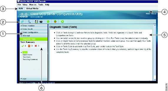
Figure 3-1 shows the UCS-SCU GUI and the different elements in the GUI and Table 3-1 shows the description of each element.
Figure 3-1 UCS-SCU GUI
This section includes the following topics:
Navigation Pane
Table 3-2 describes the elements in the Navigation Pane.
Table 3-2 Navigation Pane Elements
Server Inventory
View the server information and inventory.
Contains links to the following pages:
•
Server Information
•
To know more about the Server Inventory, go to Chapter 4 "Viewing Server Inventory."
Server Health
View the health of the subsystems on your server like CPUs, memory, power supplies, fans, storage, PCI devices, BIOS and CIMC.
To know more about Server Health, go to Chapter 5 "Viewing Server Health."
Server Configuration
Set the BIOS boot order and configure a RAID volume on attached hard drives of your server.
Contains links to the following pages:
•
•
To know more about Server Health, go to Chapter 8 "Configuring Boot Order and RAID Levels."
OS Install
Install the RHEL, SLES, and Windows operating systems in a fully unattended mode. The most recent drivers for all on-board components are added from the Tools and Drivers CD or from other supported locations during the operating system installation.
To know more about Server Health, go to Chapter 6 "Installing Operating Systems."
Diagnostic Tools
Allow you to run various types of diagnostic tests to detect server failure.
To know more about Server Health, go to Chapter 7 "Using Diagnostic Tools."
Logs
View the System Log and System Event Log of your server.
Contains links to the following pages:
•
•
To know more about Server Health, go to Chapter 9 "Viewing Logs."
Toolbar Pane
Table 3-3 lists and describes all the UCS-SCU icons that you can use to perform specific tasks.
This section describes the toolbar elements and includes the following sections:
•
•
Configuring Network
To configure a network, follow these steps:
Step 1
The Network Configuration dialog box appears.
Step 2
a.
–
–
–
–
Note
b.
–
–
–
–
Step 3
Network configuration is a one-time process and if you have not configured your network, you are prompted to configure it during the following procedures:
•
•
Performing Server Health Check
The Probe Server functionality allows to perform health check of the server subsystems. When you click Probe Server icon, the server health check is initiated.
To view the health check results, click the Server Health tab in the navigation pane.
To know more about the Server Health tab, go to Chapter 5 "Viewing Server Health.".
Saving Logs
You can use the Save Logs functionality to save your log files. Before using Save Logs, you must insert a USB flash drive or vMedia for storing the log files.
Using Server Snapshot
You can use the Server Snapshot feature in UCS SCU user interface to take a point-in-time inventory of a server. This feature allows you to compare inventories or components of a server over certain periods of time. Prior to initiating a server snapshot, ensure that you connect a USB flash drive into the server. Without a flash drive available, the log file created by the server snapshot is not saved.
When you initiate a server snapshot, UCS SCU retrieves information on the server components, and also runs a series of quick tests to determine the state of the server. Taking a server snapshot could take around 20 minutes. After the server snapshot process is complete, the log file is saved on to the USB flash drive that you specified. You can open this log file in any editor. For example, WordPad. To help compare server inventories across time periods, it is recommended that you store these log files in a location and archive it. When you have multiple logs files, you can use a comparison tool from the Internet to view differences in the server inventory.
To take a server snapshot, perform these steps:
Step 1
Without this flash drive, you cannot save the server snapshot log file. Also ensure that there is adequate space on the flash drive to save the log file.
Step 2
A dialog box prompting you to insert the USB flash drive is displayed.
Step 3
A dialog box prompts you to select the USB flash drive in which you would like to save the log file.
Step 4
The Server Snapshot process is initiated. This process could last up to 20 to 30 minutes. A dialog box indicating the progress of the server snapshot process appears. During this process, you cannot perform any other tasks on the server. At any moment during the process, you can cancel the server snapshot process by clicking Cancel in the dialog box.
Note
Step 5
The log file is saved on the USB flash drive. The log file is a text file and is saved with the server name and includes the date when the server snapshot was taken. For example: Server_C260-BASE-2646_FCH1234345_06_08_2011 is the log file name of a server snapshot taken for UCS C-260 server on August 6th, 2001.
Step 6
Note
The server snapshot feature, while running quick tests on the server, can only determine if a server component passed or failed a test. It cannot determine the reasons for a component not passing the quick test. While viewing the log file of the server snapshot process, if you notice that a server component did not pass the quick test, then check the quick test logs available under the Diagnostics Tools.
Note
The log file of the server snapshot process includes the following information:
•
•
•
•
•
•
•
•
•
•
Updating Images to Cisco Flexible Flash
You can use the UCS-SCU GUI to download the most recent versions of UCS-SCU, operating system drivers and Host Upgrade Utility (HUU). These images can be flashed to the SD card on your system on the respective partitions.
To update the images to Cisco Flexible Flash using the UCS-SCU GUI, follow these steps:
Step 1
The Cisco Flex Flash Software Update dialog box appears displaying a list of partitions.
Step 2
You can update the image to the SD card using one of the following options to update the image:
Step 3
The Cisco Flex Flash Software Update dialog box appears and the table is refreshed with the version of the image.
Step 4
From Cisco.com
To update the images to the Cisco Flexible Flash from cisco.com, follow these steps:
Step 1
If the network or user credentials are not configured, the Network Configuration dialog box appears. Else the Select Updates dialog box appears. If you need to configure the network, go to Step 2. Else, go to Step 3.
Step 2
a.
b.
c.
Step 3
Step 4
From Network
To update the image from your network to the Cisco Flexible Flash, follow these steps:
Step 1
If the network or user credentials are not configured, the Network Configuration dialog box appears. Else the Network Location dialog box appears. If you need to configure the network, go to Step 2. Else, go to Step 3.
Step 2
a.
Step 3
a.
b.
c.
d.
A file dialog box displays listing the images.
e.
f.
The selected file appears as a package name in the Network Location dialog box.
g.
Rebooting the Server
To reboot the server, follow these steps:
Step 1
The Reboot dialog box appears.
Step 2
The server is rebooted and the UCS-SCU GUI reappears.