Feedback
Table Of Contents
RAID Controller Considerations
Supported RAID Controllers and Required Cables
Supercap Power Modules (RAID Backup Units)
Mixing Drive Types in RAID Groups
Example 1—One Nonexpander and One RAID Controller with Eight Drives
Example 2—Two Nonexpanders and Two RAID Controllers with 16 Drives
Example 3—Two Expanders and One RAID Controller with Sixteen Drives
Restoring RAID Configuration After Replacing a RAID Controller
RAID Controller Considerations
This appendix provides RAID controller information, and it includes the following sections:
•
Supported RAID Controllers and Required Cables
•
•
•
Supported RAID Controllers and Required Cables
This server supports the RAID controller options and cable requirements shown in Table C-1.
Note
Table C-1 Cisco UCS C420 Server Supported RAID Options
SAS 9271CV-8i
PCIe
8 internal2
or 16 internal with expander3
Yes
0, 1, 5, 6, 10, 50, 60
•
1 UCSC-CABLE-S + 1 UCSC-CABLE-L
•
2 UCSC-CABLE-S + 2 UCSC-CABLE-L
•
2 UCSC-CABLE-S
SAS 9286CV-8e
PCIe
128 external
Yes
0, 1, 5, 6, 10, 50, 60
Cisco does not sell the cables for external drives.
1 The number and type of cables vary, depending on which type of transition card is used and how many controllers are used. See also RAID Controller Cabling.
2 When using the nonexpander-style transition card, each controller can support 8 drives; you can install two controllers and two nonexpander transition cards to control a total of 16 drives.
3 When using two expander-style transition cards, one controller can control 16 drives.
Supercap Power Modules (RAID Backup Units)
This server supports installation of two supercap power module (SCPM) backup units. The units mount to trays on the removable air baffle (see Replacing the Supercap Power Module (RAID Backup Unit)).
The SCPM is available only when using the LSI MegaRAID-CV controller cards. This module provides approximately 3 years of backup for the disk write-back cache DRAM in the case of sudden power loss by offloading the cache to the NAND flash.
Mixing Drive Types in RAID Groups
Table C-2 lists the technical capabilities for mixing hard disk drive (HDD) and solid state drive (SSD) types in a RAID group. However, see the best practices recommendations that follow for the best performance.
Table C-2 Drive Type Mixing in RAID Groups
in RAID GroupSAS HDD + SATA HDD
Yes
SAS SSD + SATA SSD
Yes
HDD + SSD
No
Best Practices For Mixing Drive Types in RAID Groups
For the best performance, follow these guidelines:
•
•
•
RAID Controller Cabling
The maximum two supported RAID controller cards should be populated in PCIe slots in the following order (see Figure 3-23):
1.
2.
Refer to the following examples for cable routing guidelines:
•
•
•
For more information about transition cards, see Replacing a Modular Drive Bay Assembly.
Example 1—One Nonexpander and One RAID Controller with Eight Drives
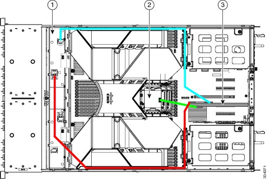
Figure C-1 shows an example of a server that is using one RAID controller in PCIe slot 3 and a nonexpander transition card to control eight drives in the modular drive bay.
Two RAID cables are required (1 UCSC-CABLE-S and 1 UCSC-CABLE-L).
•
•
•
Figure C-1 RAID Controller Cabling Guidelines, Nonexpander Transition Card
Nonexpander transition card
(shown with fan tray removed)
RAID controller card in PCIe slot 3
SCPM backup unit
(mounted to tray on air baffle)
Example 2—Two Nonexpanders and Two RAID Controllers with 16 Drives
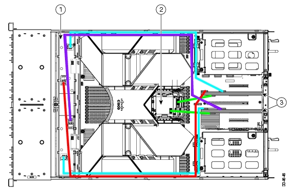
Figure C-2 shows an example of a server that is using two RAID controllers in PCIe slots 3 and 5 and two nonexpander transition cards to control eight drives in each of the two modular drive bays.
Four RAID cables are required (2 x UCSC-CABLE-L and 2 x UCSC-CABLE-S).
•
•
•
•
•
Figure C-2 RAID Controller Cabling Guidelines, Two Nonexpanders and Two Controllers
Transition cards, nonexpander version
(shown with fan tray removed)
RAID controller cards in PCIe slots 3 and 5
SCPM backup units
(two, mounted to trays on air baffle)
Example 3—Two Expanders and One RAID Controller with Sixteen Drives
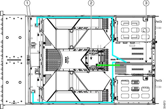
Figure C-3 shows an example of a server that is using one RAID controller in PCIe slot 3 and two expander transition cards to control eight drives in each of the two modular drive bays.
Two RAID cables are required (2 x UCSC-CABLE-S).
•
•
•
Figure C-3 RAID Controller Cabling Guidelines, Two Expanders and One Controller
Expander transition cards
(shown with fan tray removed)
RAID controller card in PCIe slot 3
SCPM backup unit
(mounted to tray on air baffle)
Restoring RAID Configuration After Replacing a RAID Controller
When you replace a RAID controller, the RAID configuration that is stored in the controller is lost.
To restore your RAID configuration to your new RAID controller, follow these steps.
Step 1
Step 2
Step 3
Note
Step 4
Foreign configuration(s) found on adapter.Press any key to continue or `C' load the configuration utility,or `F' to import foreign configuration(s) and continue.Step 5
All of the disks from your previous configuration are gone. If this isan unexpected message, then please power of your system and check your cablesto ensure all disks are present.Press any key to continue, or `C' to load the configuration utility.Step 6
•
N Virtual Drive(s) found on host adapter.•
0 Virtual Drive(s) found on host adapter.
For More Information
The LSI utilities have help documentation for more information about using the utilities.
For basic information about RAID and for using the utilities for the RAID controller cards, see the
Cisco UCS Servers RAID Guide.Full LSI documentation is also available:
LSI MegaRAID SAS Software User's Guide (for LSI MegaRAID)
http://www.lsi.com/DistributionSystem/AssetDocument/80-00156-01_RevH_SAS_SW_UG.pdf