Feedback
Table Of Contents
Overview
This chapter provides an overview of the Cisco UCS C240 server features.
External Features Overview
The figures in this chapter show an overview of external server features.
(Internal server features are illustrated in Figure 3-5.)
The server is orderable in three different versions, each with one of three different front panel/backplane configurations:
•
Cisco UCS C240 (small form-factor (SFF) drives, with 24-drive backplane and expander).
Holds up to twenty-four 2.5-inch hard drives or solid state drives.•
Holds up to sixteen 2.5-inch hard drives or solid state drives.•
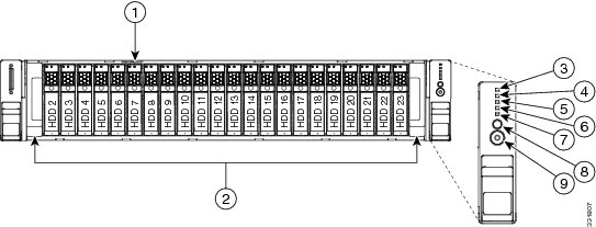
Holds up to twelve 3.5-inch hard drives.Figure 1-1 shows the front panel features of the small form-factor drives version of the server. This version of the server can be ordered with either a 16-drive backplane or a 24-drive backplane with an expander. When the 16-drive backplane is installed, only the first 16 drive bays are used.
Figure 1-1 Cisco UCS C240 Server (Small Form-Factor Drives) Front Panel Features
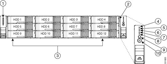
Figure 1-2 shows the front panel features of the Large Form-Factor drives version of the server. This version of the server has a 12-drive backplane with an expander.
Figure 1-2 Cisco UCS C240 Server (Large Form-Factor Drives) Front Panel Features
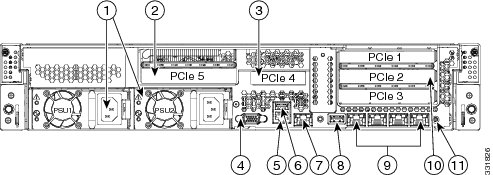
Figure 1-3 shows the rear panel features of the server (identical for all versions of the server).
Figure 1-3 Cisco UCS C240 Server Rear Panel Features
Summary of Server Features
Table 1-1 lists a summary of server features.
.
Table 1-1 Cisco UCS C240 Server Features
Chassis
Two rack-unit (2RU) chassis.
Processors
Two Intel Xeon E5-2600 Series processors.
Memory
The server provides 24 DIMM1 sockets on the motherboard.
This provides a possible total of up to 768 GB of industry-standard DDR32 memory.
Multi-bit error protection
This server supports multi-bit error protection.
Baseboard management
BMC, running Cisco Integrated Management Controller (CIMC) firmware.
Depending on your CIMC settings, the CIMC can be accessed through the
1-Gb Ethernet dedicated management port, the 1-Gb Ethernet LOM ports, or a Cisco virtual interface card.Network and management I/O
The server provides these connectors:
•
•
•
•
•
•
WoL
The 1-Gb Base-T Ethernet LAN ports support the wake-on-LAN (WoL) standard.
Power
Two power supplies: Optionally both 650 W each or both 1200 W each. Do not mix power supply types in the server.
Redundant as 1+1. See Power Specifications.
ACPI
This server supports the advanced configuration and power interface (ACPI) 4.0 standard.
Cooling
Six hot-swappable fan modules for front-to-rear cooling.
PCIe I/O
Five horizontal PCIe5 expansion slots on two risers.
See Replacing a PCIe Card for specifications of the slots.
InfiniBand
The bus slots in this server support the InfiniBand architecture.
Storage
Drives are installed into front-panel drive bays that provide hot-pluggable access. The server is orderable in three different versions, each with one of three different front panel/backplane configurations:
•
•
•
The server also contains one internal USB port on the motherboard that you can use with a USB thumb drive for additional storage.
Cisco Flexible Flash drives
The server can be ordered with up to two optional Cisco Flexible Flash drives (SD cards).
This drive is pre-loaded with four virtual drives. The four virtual drives contain, respectively, the Cisco Server Configuration Utility, the Cisco Host Upgrade Utility, the Cisco C-Series server drivers set, and a blank VD on which you can install an OS or a hypervisor. See Replacing a Cisco Flexible Flash Card for more information.
The two flash drives can be configured in a RAID 1 configuration to protect your hypervisor VD.
Disk Management
(RAID)For a list of RAID6 controller options and required cabling, see RAID Controller Considerations.
RAID Backup
There are two mounting points inside the chassis that can be used for RAID backup units. This unit can be either of the following:
•
•
Video
Resolution up to 1600x1200, 16bpp at 60 Hz. Up to 256 MB of video memory.
1 DIMM = dual inline memory module
2 DDR3 = double data rate, type 3
3 VGA = video graphics array
4 USB = universal serial bus
5 PCIe = peripheral component interconnect express
6 RAID = redundant array of independent disks