Table Of Contents
About Cisco Validated Design (CVD) Program
FlexPod Data Center with Oracle RAC on Oracle VM
Oracle Database 11g Release 2 RAC on FlexPod with Oracle Direct NFS Client
Cisco Unified Computing System
Cisco UCS B200 M3 Blade Server
Cisco UCS Virtual Interface Card 1240
Cisco UCS 6248UP Fabric Interconnect
NetApp Storage Technologies and Benefits
NetApp OnCommand System Manager 2.1
Advantage of Using Oracle VM for Oracle RAC Database
Oracle Database 11g Release 2 RAC
Oracle Database 11g Direct NFS Client
Hardware and Software used for this Solution
Cisco UCS Networking and NetApp NFS Storage Topology
Cisco UCS Manager Configuration Overview
High Level Steps for Cisco UCS Configuration
Configuring Fabric Interconnects for Blade Discovery
Configuring LAN and SAN on UCS Manager
Set Jumbo Frames in Both the Cisco UCS Fabrics
Configure vNIC and vHBA Templates
Configure Ethernet Uplink Port Channels
Create Local Disk Configuration Policy (Optional)
Service Profile creation and Association to UCS Blades
Create Service Profile Template
Create Service Profiles from Service Profile Templates
Associating Service Profile to Servers
Nexus 5548UP Configuration for FCoE Boot and NFS Data Access
Cisco Nexus 5548 A and Cisco Nexus 5548 B
Cisco Nexus 5548 A and Cisco Nexus 5548 B
Add Individual Port Descriptions for Troubleshooting
Cisco Nexus 5548 A and Cisco Nexus 5548 B
Cisco Nexus 5548 A and Cisco Nexus 5548 B
Configure Virtual Port Channels
Create VSANs, Assign and Enable Virtual Fibre Channel Ports
Create Device Aliases for FCoE Zoning
NetApp Storage Configuration Overview
Storage Configuration for FCoE Boot
Create and Configure Aggregate, Volumes and Boot LUNs
Create and Configure Initiator Group (igroup) and LUN mapping
Create and Configure Volumes and LUNs for Guest VMs
Create and Configure Initiator Group (igroup) and Mapping of LUN for Guest VM
Storage Configuration for NFS Storage Network
Create and Configure Aggregate, Volumes
Create and Configure VIF Interface (Multimode)
VIF Configuration on Controller A
VIF Configuration on Controller B
Check the NetApp Configuration
UCS Servers and Stateless Computing via FCoE Boot
Quick Summary for Boot from SAN Configuration
Oracle VM Server Install Steps and Recommendations
Oracle VM Server Network Architecture
Oracle VM Manager Installation
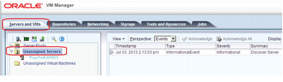
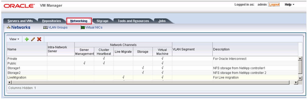
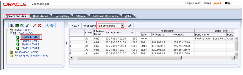
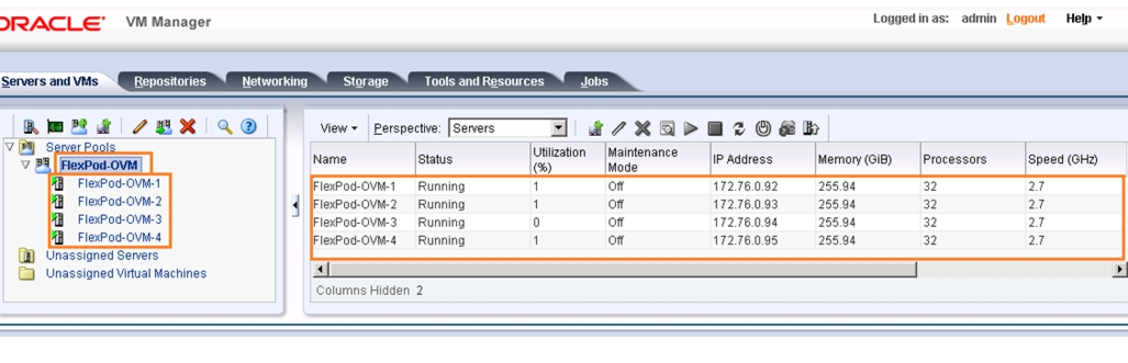
Oracle VM Server Configuration Using Oracle VM Manager
Oracle Database 11g Release 2 Grid Infrastructure with RAC Option Deployment
Installing Oracle RAC 11g Release 2
Workloads and Database Configuration
Performance Data from the Tests
Destructive and Hardware failover Tests
Appendix A: Nexus 5548UP Configuration
Nexus 5548 Fabric A Configuration
Nexus 5548 Fabric B Configuration
Appendix B: Verify Oracle RAC Cluster Status Command Output
FlexPod Data Center with Oracle RAC on Oracle VM with 7-ModeDeployment Guide for FlexPod with Oracle Database 11g Release 2 RAC on Oracle VM 3.1.1November 22, 2013
Building Architectures to Solve Business Problems
About the Authors
Niranjan, Technical Marketing Engineer, SAVBU, Cisco SystemsNiranjan Mohapatra is a Technical Marketing Engineer in Cisco Systems Data Center Group (DCG) and specialist on Oracle RAC RDBMS. He has over 14 years of extensive experience on Oracle RAC Database and associated tools. Niranjan has worked as a TME and a DBA handling production systems in various organizations. He holds a Master of Science (MSc) degree in Computer Science and is also an Oracle Certified Professional (OCP -DBA) and NetApp accredited storage architect. Niranjan also has strong background in Cisco UCS, NetApp Storage and Virtualization.
Acknowledgment
For their support and contribution to the design, validation, and creation of the Cisco Validated Design, I would like to thank:
•
Siva Sivakumar- Cisco
•
•
•
•
•
About Cisco Validated Design (CVD) Program
The CVD program consists of systems and solutions designed, tested, and documented to facilitate faster, more reliable, and more predictable customer deployments. For more information visit:
http://www.cisco.com/go/designzone
ALL DESIGNS, SPECIFICATIONS, STATEMENTS, INFORMATION, AND RECOMMENDATIONS (COLLECTIVELY, "DESIGNS") IN THIS MANUAL ARE PRESENTED "AS IS," WITH ALL FAULTS. CISCO AND ITS SUPPLIERS DISCLAIM ALL WARRANTIES, INCLUDING, WITHOUT LIMITATION, THE WARRANTY OF MERCHANTABILITY, FITNESS FOR A PARTICULAR PURPOSE AND NONINFRINGEMENT OR ARISING FROM A COURSE OF DEALING, USAGE, OR TRADE PRACTICE. IN NO EVENT SHALL CISCO OR ITS SUPPLIERS BE LIABLE FOR ANY INDIRECT, SPECIAL, CONSEQUENTIAL, OR INCIDENTAL DAMAGES, INCLUDING, WITHOUT LIMITATION, LOST PROFITS OR LOSS OR DAMAGE TO DATA ARISING OUT OF THE USE OR INABILITY TO USE THE DESIGNS, EVEN IF CISCO OR ITS SUPPLIERS HAVE BEEN ADVISED OF THE POSSIBILITY OF SUCH DAMAGES.
THE DESIGNS ARE SUBJECT TO CHANGE WITHOUT NOTICE. USERS ARE SOLELY RESPONSIBLE FOR THEIR APPLICATION OF THE DESIGNS. THE DESIGNS DO NOT CONSTITUTE THE TECHNICAL OR OTHER PROFESSIONAL ADVICE OF CISCO, ITS SUPPLIERS OR PARTNERS. USERS SHOULD CONSULT THEIR OWN TECHNICAL ADVISORS BEFORE IMPLEMENTING THE DESIGNS. RESULTS MAY VARY DEPENDING ON FACTORS NOT TESTED BY CISCO.
The Cisco implementation of TCP header compression is an adaptation of a program developed by the University of California, Berkeley (UCB) as part of UCB's public domain version of the UNIX operating system. All rights reserved. Copyright © 1981, Regents of the University of California.
Cisco and the Cisco Logo are trademarks of Cisco Systems, Inc. and/or its affiliates in the U.S. and other countries. A listing of Cisco's trademarks can be found at http://www.cisco.com/go/trademarks. Third party trademarks mentioned are the property of their respective owners. The use of the word partner does not imply a partnership relationship between Cisco and any other company. (1005R)
Any Internet Protocol (IP) addresses and phone numbers used in this document are not intended to be actual addresses and phone numbers. Any examples, command display output, network topology diagrams, and other figures included in the document are shown for illustrative purposes only. Any use of actual IP addresses or phone numbers in illustrative content is unintentional and coincidental.
© 2013 Cisco Systems, Inc. All rights reserved.
FlexPod Data Center with Oracle RAC on Oracle VM
Executive Summary
Industry trends indicate a vast data center transformation toward shared infrastructures. Enterprise customers are moving away from silos of information and moving toward shared infrastructures to virtualized environments and eventually to the cloud to increase agility and operational efficiency, optimize resource utilization, and reduce costs.
FlexPod is a pretested data center solution built on a flexible, scalable, shared infrastructure consisting of Cisco UCS servers with Cisco Nexus® switches and NetApp unified storage systems running Data ONTAP. The FlexPod components are integrated and standardized to help you eliminate the guesswork and achieve timely, repeatable, consistent deployments. FlexPod has been optimized with a variety of mixed application workloads and design configurations in various environments such as virtual desktop infrastructure and secure multitenancy environments.
One main benefit of the FlexPod architecture is the ability to customize the environment to suit a customer's requirements. This is why the reference architecture detailed in this document highlights the resiliency, cost benefit, and ease of deployment of an FCoE-based storage solution. A storage system capable of serving multiple protocols across a single interface is the customer's choice and investment protection.
Large enterprises are adopting virtualization, have much higher I/O requirements. For them, FCoE is a better solution. Customers who have adopted Cisco® MDS 9000 family switches will probably prefer FCoE as it offers inherent coexistence with Fibre Channel, with no need to migrate existing Fibre Channel infrastructures. FCoE will take a large share of the SAN market. It will not make iSCSI obsolete, but it will reduce its potential market.
Virtualization started as a means of server consolidation, but IT needs are evolving as data centers are becoming service providers. An isolated hypervisor cannot provide the speed and time to market required to deploy a complete application stack. To realize the full benefits of virtualization, Oracle offers an integrated virtualization from desktop to the data center and enables you to virtualize and manage your complete hardware and software stack.
Oracle Real Application Clusters (RAC) allows an Oracle Database to run any packaged or custom applications, unchanged across a pool of servers. This provides the highest levels of RAS (Reliability, Availability and Scalability). If a server in the pool fails, the Oracle database continues to run on the remaining servers. When you need more processing power, simply add another server to the pool without taking users offline. Oracle Real Application Clusters provide a foundation for Oracle's Private Cloud Architecture. Oracle RAC 11g Release 2 in addition enables customers to build a dynamic private cloud infrastructure.
FlexPod Data Center with Oracle RAC on Oracle VM includes NetApp storage, Cisco® networking, Cisco UCS, and Oracle virtualization software in a single package. This solution is deployed and tested on a defined set of hardware and software.
This Cisco Validated Design describes how the Cisco Unified Computing System™ can be used in conjunction with NetApp FAS storage systems to implement an optimized system to run Oracle Real Application Clusters (RAC) in Oracle VM.
Target Audience
This document is intended to assist solution architects, project managers, infrastructure managers, sales engineers, field engineers, and consultants in planning, designing, and deploying Oracle Database 11g Release 2 RAC hosted on FlexPod. This document assumes that the reader has an architectural understanding of the Cisco Unified Computing System, Oracle 11g Release 2 Grid Infrastructure, Oracle Real Application Clusters, Oracle VM, NetApp storage systems, and related software.
Purpose of this Guide
This FlexPod CVD demonstrates how enterprises can apply best practices to deploy Oracle Database 11g Release 2 RAC using Oracle VM, Cisco Unified Computing System, Cisco Nexus family switches, and NetApp FAS storage. This design solution shows the deployment and scaling of a four-node Oracle Database 11g Release 2 RAC in a virtualized environment using typical OLTP and DSS workloads to demonstrate stability, performance and resiliency design as demanded by mission critical data center deployments.
Business Needs
Business applications are moving into integrated stacks consisting of compute, network, and storage. This FlexPod solution helps to reduce costs and complexity of a traditional Oracle Database 11g Release 2 RAC deployment. Following business needs for Oracle Database 11g Release 2 RAC deployment on Oracle VM are addressed by this solution.
•
•
•
•
•
•
•
•
•
Solution Overview
Oracle Database 11g Release 2 RAC on FlexPod with Oracle Direct NFS Client
This solution provides an end-to-end architecture with Cisco UCS, Oracle, and NetApp technologies that demonstrate the implementation of Oracle Database 11g Release 2 RAC on FlexPod and Oracle VM. This solution demonstrates the implementation, capabilities and advantages of Oracle Database 11g Release 2 RAC and Oracle VM on FlexPod.
The following infrastructure and software components are used for this solution:
•
•
•
•
•
•
•
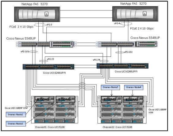
* Cisco Unified Computing System includes all the hardware and software components required for this deployment solution.Figure 1 shows the architecture and the connectivity layout for this deployment model.
Figure 1 Solution Architecture
Let us look at individual components that define this architecture.
Technology Overview
Cisco Unified Computing System
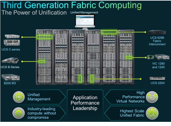
Figure 2 Cisco Unified Computing System
The Cisco Unified Computing System is a third-generation data center platform that unites computing, networking, storage access, and virtualization resources into a cohesive system designed to reduce TCO and increase business agility. The system integrates a low-latency, lossless 10 Gigabit Ethernet (10GbE) unified network fabric with enterprise-class, x86-architecture servers. The system is an integrated, scalable, multi-chassis platform in which all the resources participate in a unified management domain that is controlled and managed centrally.
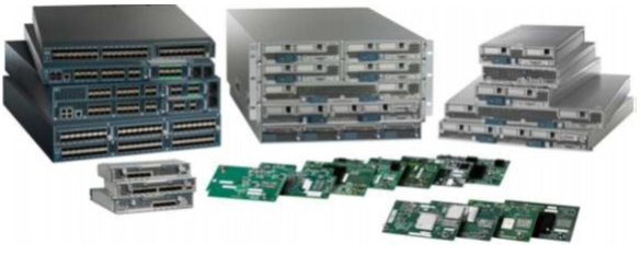
Figure 3 Cisco UCS Components
Figure 4 Cisco UCS Components
The main components of the Cisco UCS are:
•
The system is based on an entirely new class of computing system that incorporates blade servers based on Intel Xeon® E5-2600 Series Processors. Cisco UCS B-Series Blade Servers work with virtualized and non-virtualized applications to increase performance, energy efficiency, flexibility and productivity.
•
The system is integrated onto a low-latency, lossless, 80-Gbps unified network fabric. This network foundation consolidates LANs, SANs, and high-performance computing networks which are separate networks today. The unified fabric lowers costs by reducing the number of network adapters, switches, and cables, and by decreasing the power and cooling requirements.
•
The system provides consolidated access to both storage area network (SAN) and network-attached storage (NAS) over the unified fabric. By unifying storage access, Cisco UCS can access storage over Ethernet, Fiber Channel, Fiber Channel over Ethernet (FCoE), and iSCSI. This provides customers with the options for setting storage access and investment protection. Additionally, server administrators can reassign storage-access policies for system connectivity to storage resources, thereby simplifying storage connectivity and management for increased productivity.
•
The system uniquely integrates all the system components which enable the entire solution to be managed as a single entity by the Cisco UCS Manager. The Cisco UCS Manager has an intuitive graphical user interface (GUI), a command-line interface (CLI), and a robust application programming interface (API) to manage all the system configuration and operations.
The Cisco UCS is designed to deliver:
•
•
•
•
•
Cisco UCS Blade Chassis
The Cisco UCS 5100 Series Blade Server Chassis is a crucial building block of the Cisco Unified Computing System, delivering a scalable and flexible blade server chassis.
The Cisco UCS 5108 Blade Server Chassis is six rack units (6RU) high and can mount in an industry-standard 19-inch rack. A single chassis can house up to eight half-width Cisco UCS B-Series Blade Servers and can accommodate both half-width and full-width blade form factors.
Four single-phase, hot-swappable power supplies are accessible from the front of the chassis. These power supplies are 92 percent efficient and can be configured to support non-redundant, N+ 1 redundant and grid-redundant configurations. The rear of the chassis contains eight hot-swappable fans, four power connectors (one per power supply), and two I/O bays for Cisco UCS 2208 XP Fabric Extenders.
A passive mid-plane provides up to 40 Gbps of I/O bandwidth per server slot and up to 80 Gbps of I/O bandwidth for two slots. The chassis is capable of supporting future 80 Gigabit Ethernet standards.
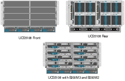
Figure 5 Cisco Blade Server Chassis (Front, Rear and Populated with Blades View)
Cisco UCS B200 M3 Blade Server
The Cisco UCS B200 M3 Blade Server is a half-width, two-socket blade server. The system uses two Intel Xeon® E5-2600 Series Processors, up to 384 GB of DDR3 memory, two optional hot-swappable small form factor (SFF) serial attached SCSI (SAS) disk drives, and two VIC adaptors that provides up to 80 Gbps of I/O throughput. The server balances simplicity, performance, and density for production-level virtualization and other mainstream data center workloads.
Figure 6 Cisco UCS B200 M3 Blade Server

Cisco UCS Virtual Interface Card 1240
A Cisco innovation, the Cisco UCS VIC 1240 is a four-port 10 Gigabit Ethernet, FCoE-capable modular LAN on motherboard (mLOM) designed exclusively for the M3 generation of Cisco UCS B-Series Blade Servers. When used in combination with an optional port expander, the Cisco UCS VIC 1240 capabilities can be expanded to eight ports of 10 Gigabit Ethernet.
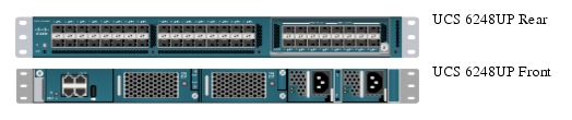
Cisco UCS 6248UP Fabric Interconnect
•
•
Figure 7 Cisco UCS 6248UP Fabric Interconnect
Cisco UCS Manager
Cisco UCS Manager is an embedded, unified manager that provides a single point of management for Cisco UCS. Cisco UCS Manager can be accessed through an intuitive GUI, a command-line interface (CLI), or the comprehensive open XML API. It manages the physical assets of the server and storage and LAN connectivity, and it is designed to simplify the management of virtual network connections through integration with several major hypervisor vendors. It provides IT departments with the flexibility to allow people to manage the system as a whole, or to assign specific management functions to individuals based on their roles as managers of server, storage, or network hardware assets. It simplifies operations by automatically discovering all the components available on the system and enabling a stateless model for resource use.
Some of the key elements managed by Cisco UCS Manager include:
•
•
•
•
•
•
Cisco UCS is designed from the start to be programmable and self-integrating. A server's entire hardware stack, ranging from server firmware and settings to network profiles, is configured through model-based management. With Cisco virtual interface cards (VICs), even the number and type of I/O interfaces is programmed dynamically, making every server ready to power any workload at any time.
With model-based management, administrators manipulate a desired system configuration and associate a model's policy driven service profiles with hardware resources, and the system configures itself to match requirements. This automation accelerates provisioning and workload migration with accurate and rapid scalability. The result is increased IT staff productivity, improved compliance, and reduced risk of failures due to inconsistent configurations. This approach represents a radical simplification compared to traditional systems, reducing capital expenditures (CAPEX) and operating expenses (OPEX) while increasing business agility, simplifying and accelerating deployment, and improving performance.
UCS Service Profiles
Figure 8 Traditional Provisioning Approach
A server's identity is made up of many properties such as UUID, boot order, IPMI settings, BIOS firmware, BIOS settings, RAID settings, disk scrub settings, number of NICs, NIC speed, NIC firmware, MAC and IP addresses, number of HBAs, HBA WWNs, HBA firmware, FC fabric assignments, QoS settings, VLAN assignments, remote keyboard/video/monitor etc. I think you get the idea. It's a LONG list of "points of configuration" that need to be configured to give this server its identity and make it unique from every other server within your data center. Some of these parameters are kept in the hardware of the server itself (like BIOS firmware version, BIOS settings, boot order, FC boot settings, etc.) while some settings are kept on your network and storage switches (like VLAN assignments, FC fabric assignments, QoS settings, ACLs, and so on.). This results in following server deployment challenges:
Lengthy deployment cycles
•
•
•
Response time to business needs
•
•
•
Limited OS and application mobility
•
•
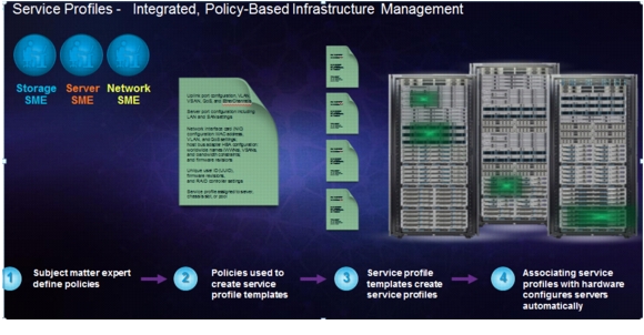
Cisco UCS has uniquely addressed these challenges with the introduction of service profiles (see Figure 9) that enables integrated, policy based infrastructure management. UCS Service Profiles hold the DNA for nearly all configurable parameters required to set up a physical server. A set of user defined policies (rules) allow quick, consistent, repeatable, and secure deployments of UCS servers.
Figure 9 Service Profiles
UCS Service Profiles contain values for a server's property settings, including virtual network interface cards (vNICs), MAC addresses, boot policies, firmware policies, fabric connectivity, external management, and high availability information. By abstracting these settings from the physical server into a Cisco Service Profile, the Service Profile can then be deployed to any physical compute hardware within the Cisco UCS domain. Furthermore, Service Profiles can, at any time, be migrated from one physical server to another. This logical abstraction of the server personality separates the dependency of the hardware type or model and is a result of Cisco's unified fabric model (rather than overlaying software tools on top).
This innovation is still unique in the industry despite competitors claiming to offer similar functionality. In most cases, these vendors must rely on several different methods and interfaces to configure these server settings. Furthermore, Cisco is the only hardware provider to offer a truly unified management platform, with UCS Service Profiles and hardware abstraction capabilities extending to both blade and rack servers.
Some of key features and benefits of UCS service profiles are:
•
A service profile contains configuration information about the server hardware, interfaces, fabric connectivity, and server and network identity. The Cisco UCS Manager provisions servers utilizing service profiles. The UCS Manager implements a role-based and policy-based management focused on service profiles and templates. A service profile can be applied to any blade server to provision it with the characteristics required to support a specific software stack. A service profile allows server and network definitions to move within the management domain, enabling flexibility in the use of system resources.
Service profile templates are stored in the Cisco UCS 6200 Series Fabric Interconnects for reuse by server, network, and storage administrators. Service profile templates consist of server requirements and the associated LAN and SAN connectivity. Service profile templates allow different classes of resources to be defined and applied to a number of resources, each with its own unique identities assigned from predetermined pools.
The UCS Manager can deploy the service profile on any physical server at any time. When a service profile is deployed to a server, the Cisco UCS Manager automatically configures the server, adapters, Fabric Extenders, and Fabric Interconnects to match the configuration specified in the service profile. A service profile template parameterizes the UIDs that differentiate between server instances.
This automation of device configuration reduces the number of manual steps required to configure servers, Network Interface Cards (NICs), Host Bus Adapters (HBAs), and LAN and SAN switches.
•
Cisco UCS Manager provides centralized management capabilities, creates a unified management domain, and serves as the central nervous system of the Cisco UCS. Cisco UCS Manager is embedded device management software that manages the system from end-to-end as a single logical entity through an intuitive GUI, CLI, or XML API. Cisco UCS Manager implements role- and policy-based management using service profiles and templates. This construct improves IT productivity and business agility. Now infrastructure can be provisioned in minutes instead of days, shifting IT's focus from maintenance to strategic initiatives.
•
Cisco UCS resources are abstract in the sense that their identity, I/O configuration, MAC addresses and WWNs, firmware versions, BIOS boot order, and network attributes (including QoS settings, ACLs, pin groups, and threshold policies) all are programmable using a just-in-time deployment model. A service profile can be applied to any blade server to provision it with the characteristics required to support a specific software stack. A service profile allows server and network definitions to move within the management domain, enabling flexibility in the use of system resources. Service profile templates allow different classes of resources to be defined and applied to a number of resources, each with its own unique identities assigned from predetermined pools.
Cisco Nexus 5548UP Switch
The Cisco Nexus 5548UP is a 1RU 1 Gigabit and 10 Gigabit Ethernet switch offering up to 960 gigabits per second throughput and scaling up to 48 ports. It offers 32 1/10 Gigabit Ethernet fixed enhanced Small Form-Factor Pluggable (SFP+) Ethernet/FCoE or 1/2/4/8-Gbps native FC unified ports and three expansion slots. These slots have a combination of Ethernet/FCoE and native FC ports.
Figure 10 Cisco Nexus 5548UP switch
The Cisco Nexus 5548UP Switch delivers innovative architectural flexibility, infrastructure simplicity, and business agility, with support for networking standards. For traditional, virtualized, unified, and high-performance computing (HPC) environments, it offers a long list of IT and business advantages, including:
•
–
–
–
–
–
–
–
•
–
–
–
–
–
•
–
–
–
•
–
–
–
–
NetApp Storage Technologies and Benefits
NetApp storage platform can handle different type of files and data from various sources—including user files, e-mail, and databases. Data ONTAP is the fundamental NetApp software platform that runs on all the NetApp storage systems. Data ONTAP is a highly optimized, scalable operating system that supports mixed NAS and SAN environments and a range of protocols, including Fiber Channel, iSCSI, FCoE, NFS, and CIFS. The platform includes the Write Anywhere File Layout (WAFL®) file system and storage virtualization capabilities. By leveraging the Data ONTAP platform, the NetApp Unified Storage Architecture offers the flexibility to manage, support, and scale to different business environments by using a common knowledge base and tools. This architecture enables users to collect, distribute, and manage data from all locations and applications at the same time. This allows the investment to scale by standardizing processes, cutting management time, and increasing availability. Figure 11 shows the various NetApp Unified Storage Architecture platforms.
Figure 11 NetApp Unified Storage Architecture Platforms
The NetApp storage hardware platform used in this solution is the FAS3270A. The FAS3200 series is an excellent platform for primary and secondary storage for an Oracle Database 11g Release 2 Grid Infrastructure deployment.
A number of NetApp tools and enhancements are available to augment the storage platform. These tools assist in deployment, backup, recovery, replication, management, and data protection. This solution makes use of a subset of these tools and enhancements.
Storage Architecture
The storage design for any solution is a critical element that is typically responsible for a large percentage of the solution's overall cost, performance, and agility.
The basic architecture of the storage system's software is shown in the figure below. A collection of tightly coupled processing modules handles CIFS, FCP, FCoE, HTTP, iSCSI, and NFS requests. A request starts in the network driver and moves up through network protocol layers and the file system, eventually generating disk I/O, if necessary. When the file system finishes the request, it sends a reply back to the network. The administrative layer at the top supports a command line interface (CLI) similar to UNIX® that monitors and controls the modules below. In addition to the modules shown, a simple real-time kernel provides basic services such as process creation, memory allocation, message passing, and interrupt handling.
The networking layer is derived from the same Berkeley code used by most UNIX systems, with modifications made to communicate efficiently with the storage appliance's file system. The storage appliance provides transport-independent seamless data access using block- and file-level protocols from the same platform. The storage appliance provides block-level data access over an FC SAN fabric using FCP and over an IP-based Ethernet network using iSCSI. File access protocols such as NFS, CIFS, HTTP, or FTP provide file-level access over an IP-based Ethernet network.
Figure 12 Storage Architecture
RAID-DP
RAID-DP® is NetApp's implementation of double-parity RAID 6, which is an extension of NetApp's original Data ONTAP WAFL® RAID 4 design. Unlike other RAID technologies, RAID-DP provides the ability to achieve a higher level of data protection without any performance impact, while consuming a minimal amount of storage. For more information on RAID-DP, see: http://www.netapp.com/us/products/platform-os/raid-dp.html
Snapshot
NetApp Snapshot technology provides zero-cost, near-instantaneous backup and point-in-time copies of the volume or LUN by preserving the Data ONTAP WAFL consistency points.
Creating Snapshot copies incurs minimal performance effect because data is never moved, as it is with other copy-out technologies. The cost for Snapshot copies is at the rate of block-level changes and not 100% for each backup, as it is with mirror copies. Using Snapshot can result in savings in storage cost for backup and restore purposes and opens up a number of efficient data management possibilities.
FlexVol
NetApp® FlexVol® storage-virtualization technology enables you to respond to changing storage needs fast, lower your overhead, avoid capital expenses, and reduce disruption and risk. FlexVol technology aggregates physical storage in virtual storage pools, so you can create and resize virtual volumes as your application needs change.
With FlexVol you can improve—even double—the utilization of your existing storage and save the expense of acquiring more disk space. In addition to increasing storage efficiency, you can improve I/O performance and reduce bottlenecks by distributing volumes across all the available disk drives.
NetApp Flash Cache
NetApp® Flash Cache controller-attached PCIe intelligent caching instead of more hard disk drives (HDDs) or solid-state drives (SSDs) to optimize your storage system performance.
Flash Cache speeds data access through intelligent caching of recently read user data or NetApp metadata. No setup or ongoing administration is needed, and operations can be tuned. Flash Cache works with all the NetApp storage protocols and software, enabling you to:
•
•
•
For more information on RAID-DP, see: http://www.netapp.com/us/products/storage-systems/flash-cache/index.aspx
NetApp OnCommand System Manager 2.1
System Manager is a powerful management tool for NetApp storage that allows administrators to manage a single NetApp storage system as well as clusters, quickly and easily.
Some of the benefits of the System Manager Tool are:
•
•
•
•
•
•
Oracle VM 3.1.1
Oracle VM is a platform that provides a fully equipped environment with all the latest benefits of virtualization technology. Oracle VM enables you to deploy operating systems and application software within a supported virtualization environment. Oracle VM is a Xen-based hypervisor that runs at nearly bare-metal speeds.
Oracle VM Architecture
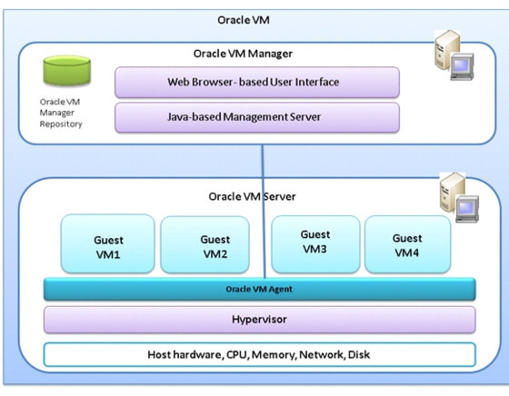
Figure 13 shows the Oracle VM architecture.
Figure 13 Oracle VM Architecture
The Oracle VM architecture has three main parts:
•
Provides the user interface, which is a standard ADF (Application Development Framework) web application, to manage Oracle VM Servers. Manages virtual machine lifecycle, including creating virtual machines from installation media or from a virtual machine template, deleting, powering off, uploading, deployment and live migration of virtual machines. Manages resources, including ISO files, virtual machine templates and sharable hard disks.
•
A self-contained virtualization environment designed to provide a lightweight, secure, server-based platform for running virtual machines. Oracle VM Server is based upon an updated version of the underlying Xen hypervisor technology, and includes Oracle VM Agent.
•
Installed with Oracle VM Server. It communicates with Oracle VM Manager for management of virtual machines.
Advantage of Using Oracle VM for Oracle RAC Database
Oracle's virtualization technologies are an excellent delivery vehicle for Independent Software Vendors (ISV's) looking for a simple, easy-to-install and easy-to-support application delivery solution.
Oracle VM providing software based virtualization infrastructure (Oracle VM) and the market leading high availability solution Oracle Real Application Clusters (RAC), Oracle now offers a highly available, grid-ready virtualization solution for your data center, combining all the benefits of a fully virtualized environment.
The combination of Oracle VM and Oracle RAC enables a better server consolidation (RAC databases with under utilized CPU resources or peaky CPU utilization can often benefit from consolidation with other workloads using server virtualization) sub-capacity licensing, and rapid provisioning. Oracle RAC on Oracle VM also supports the creation of non-production virtual clusters on a single physical server for production demos and test/dev environments. This deployment combination permits dynamic changes to pre-configured database resources for agile responses to changing service level requirements common in consolidated environments.
Oracle VM is the only software based virtualization solution that is fully supported and certified for Oracle real Application Clusters.
There are several reasons why you may want to run Oracle RAC in an Oracle VM environment. The more more common reasons are:
•
Oracle RAC databases or Oracle RAC One Node databases with under utilized CPU resources or variable CPU utilization can often benefit from consolidation with other workloads using server virtualization. A typical use case for this scenario would be the consolidation of several Oracle databases (Oracle RAC, Oracle RAC One Node or Oracle single instance databases) into a single Oracle RAC database or multiple Oracle RAC databases where the hosting Oracle VM guests have pre-defined resource limits configured for each VM guest.
•
The current Oracle licensing model requires the Oracle RAC database to be licensed for all CPUs on each server in the cluster. Sometimes customers wish to use only a subset of the CPUs on the server for a particular Oracle RAC database. Oracle VM can be configured in such way that it is recognized as a hard partition. Hard partitions allow customers to only license those CPUs used by the partition instead of licensing all CPUs on the physical server. More information on sub-capacity licensing using hard partitioning can be found in the Oracle partitioning paper. For more information on using hard partitioning with Oracle VM refer to the "Hard Partitioning with Oracle VM" white paper.
•
Oracle VM enables the creation of a virtual cluster on a single physical server. This use case is particularly interesting for product demos, educational settings, and test environments. This configuration should never be used to run production Oracle RAC environments. The following are valid deployments for this use case:
–
–
–
•
The provisioning time of a new application consists of the server (physical or virtual) deployment time, and the software install and configuration time. Oracle VM can help reduce the deployment time for both of these components. Oracle VM supports the ability to create deployment templates. These templates can then be used to rapidly provision new (Oracle RAC) systems.
For Oracle RAC, currently only para-virtualized VM (PVM) mode is supported. Some of the advantages of using para-virtualized VM mode is mentioned in the next sub-section.
Para-virtualized VM (PVM)
Guest virtual machines running on Oracle VM server should be configured in para-virtualized virtualization mode. In this mode the kernel of the guest operating system is modified to distinguish that it is running on a hypervisor instead of on the bare metal hardware. As a result, I/O actions and system clock timers in particular are handled more efficiently, as compared with non para-virtualized systems where I/O hardware and timers have to be emulated in the operating system. Oracle VM supports PV kernels for Oracle Linux and Red Hat Enterprise Linux, offering better performance and scalability.
Oracle Database 11g Release 2 RAC
Oracle Database 11g Release 2 provides the foundation for IT to successfully deliver more information with higher quality of service, reduce the risk of change within IT, and make more efficient use of IT budgets.
Oracle Database 11g Release 2 Enterprise Edition provides industry-leading performance, scalability, security, and reliability on a choice of clustered or single-servers with a wide range of options to meet user needs. Cloud computing relieves users from concerns about where data resides and which computer processes the requests. Users request information or computation and have it delivered - as much as they want, whenever they want it. For a DBA, the cloud is about resource allocation, information sharing, and high availability. Oracle Database with Real Application Clusters provide the infrastructure for your database cloud. Oracle Automatic Storage Management provides the infrastructure for a storage cloud. Oracle Enterprise Manager Cloud Control provides you with holistic management of your could.
Oracle Database 11g Direct NFS Client
Direct NFS client is an Oracle developed, integrated, and optimized client that runs in user space rather than within the operating system kernel. This architecture provides for enhanced scalability and performance over traditional NFS v3 clients. Unlike traditional NFS implementations, Oracle supports asynchronous I/O across all operating system environments with Direct NFS client. In addition, performance and scalability are dramatically improved with its automatic link aggregation feature. This allows the client to scale across as many as four individual network pathways with the added benefit of improved resiliency when Network connectivity is occasionally compromised. It also allows Direct NFS client to achieve near block level Performance. For more information on Direct NFS Client comparison to block protocols, see: http://media.netapp.com/documents/tr-3700.pdf.
Design Topology
This section presents physical and logical high-level design considerations for Cisco UCS networking and computing on NetApp storage for Oracle Database 11g Release 2 RAC deployments.
Hardware and Software used for this Solution
Table 1 shows the Software and Hardware Used for Oracle Database 11g Release 2 Grid Infrastructure with the Oracle RAC Option Deployment
Cisco UCS Networking and NetApp NFS Storage Topology
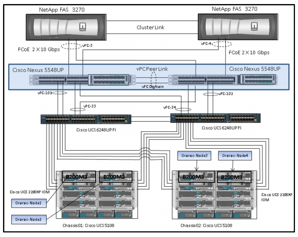
This section explains Cisco UCS networking and computing design considerations when deploying Oracle Database 11g Release 2 RAC in an NFS Storage Design. In this design, the NFS traffic is isolated from the regular management and application data network using the same Cisco UCS infrastructure by defining logical VLAN networks to provide better data security. Figure 14, presents a detailed view of the physical topology, and some of the main components of Cisco UCS in an NFS network design.
Figure 14 Cisco UCS Networking and NFS Storage Network Topology
Table 2 vPC Details
Public
33
760,761,191,120,121
Private
34
760,761,191,120,121
NetApp-Storage1
3
120,121
NetApp-Storage2
4
120,121
As shown in Figure 14, a pair of Cisco UCS 6248UP fabric interconnects carries both storage and network traffic from the blades with the help of Cisco Nexus 5548UP switch. The 10GB FCoE traffic leaves the UCS Fabrics through Nexus 5548 Switches to NetApp Array. As larger enterprises are adopting virtualization, they have much higher I/O requirements. To effectively handle the higher I/O requirements, FCoE boot is a better solution.
Both the fabric interconnect and the Cisco Nexus 5548UP switch are clustered with the peer link between them to provide high availability. Two virtual Port Channels (vPCs) are configured to provide public network, private network and storage access paths for the blades to northbound switches. Each vPC has VLANs created for application network data, NFS storage data, and management data paths. For more information about vPC configuration on the Cisco Nexus 5548UP Switch, see:
As illustrated in Figure 14, 8 (4 per chassis) links go to Fabric Interconnect A (ports 1 through 8). Similarly, 8 links go to Fabric Interconnect B. Fabric Interconnect A links are used for Oracle Public network and NFS Storage Network traffic and Fabric Interconnect B links are used for Oracle private interconnect traffic and NFS Storage network traffic.
Note
Cisco UCS Manager Configuration Overview
High Level Steps for Cisco UCS Configuration
Given below are high level steps involved for a Cisco UCS configuration:
1.
a.
b.
2.
a.
b.
c.
d.
3.
a.
b.
c.
4.
a.
b.
c.
d.
e.
5.
6.
Details for each step are discussed in the following subsequent sections.
Configuring Fabric Interconnects for Blade Discovery
Cisco UCS 6248 UP Fabric Interconnects are configured for redundancy. It provides resiliency in case of failures. The first step is to establish connectivity between the blades and fabric interconnects.
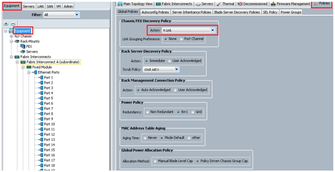
Configure Global Policies
To configure global policies, follow theses steps
1.
2.
3.
4.
Figure 15 Configure Global Policy
Configuring Server Ports
To configure server ports, follow these steps:
1.
2.
3.
4.
5.
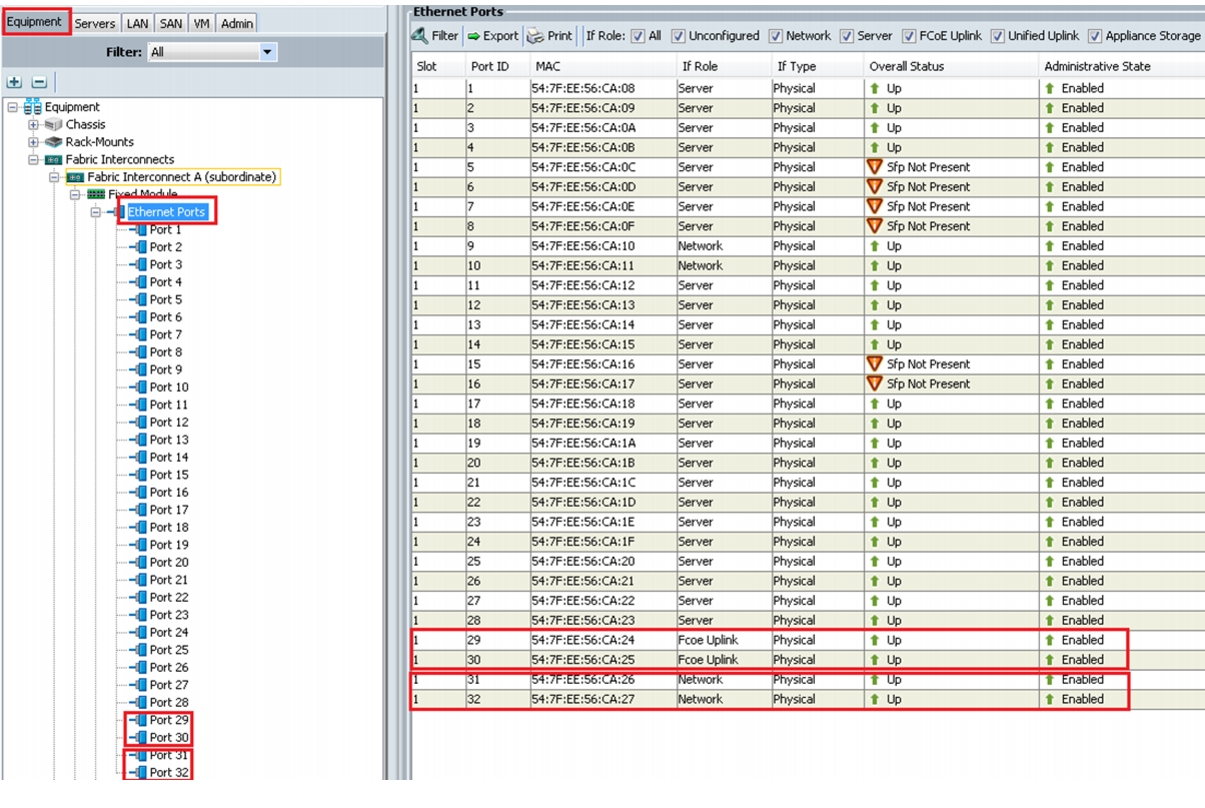
Figure 16 Configuring Ethernet Ports as Server Ports
Figure 17 Configured Server Ports
Configuring LAN and SAN on UCS Manager
Perform LAN and SAN configuration steps in UCS Manager as shown in the figures below.
Configure and Enable Ethernet LAN Uplink Ports
To configure and enable Ethernet LAN uplink ports, follow these steps:
1.
2.
3.
4.
5.
Figure 18 Configure Ethernet LAN Uplink Ports
As shown Figure 18, we have selected Port 31 and 32 on Fabric interconnect A and configured them as Ethernet uplink ports. Repeat the same step on Fabric interconnect B to configure Port 31 and 32 as Ethernet uplink ports. We have selected port 29 and Port 30 on both the fabrics and configured them as FCoE Uplink ports for FCoE boot.
Note
Important Oracle RAC Best Practices and Recommendations for vLANs and vNIC Configuration
•
For this configuration, we have created VLAN 120 and VLAN 121 for storage access, and VSAN 101 and VSAN 102 for FCoE boot.
•
Note
Configure VLAN
To configure VLAN, follow these steps:
1.
2.
3.
4.
In this solution, we need to create five VLANs:
•
•
•
•
Note
Figure 19 Create VLAN for Public Network
In Figure 19, we have highlighted VLAN 760 creation for public network. It is also very important that you create both VLANs as global across both fabric interconnects. This way, VLAN identity is maintained across the fabric interconnects in case of NIC failover.
Create VLANs for public, storage and live migration. In case you are using Oracle HAIP feature, you may have to configure additional vlans to be associated with additional vnics as well.
Here is the summary of VLANs once you complete VLAN creation.
•
•
•
•
Note
Figure 20 summarizes all the VLANs for Public and Private network and Storage access.
Figure 20 VLAN Summary
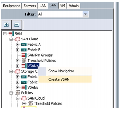
Configure VSAN
To configure VSAN, follow these steps:
1.
2.
3.
4.
Note
Figure 21 Configuring VSAN in UCS Manager
Figure 22 Creating VSAN for Fabric A
We have created a VSAN on both the Fabrics. For the VSAN on Fabric A the VSAN ID is 101 and FCoE VLAN ID is 101 and similarly, for Fabric B the VSAN ID is 102 and the FCoE VLAN ID is 102.
Note
Figure 23 shows the created VSANs in UCS Manager.
Figure 23 VSAN Summary
Configure Pools
After VLANs and VSAN are created, configure pools for UUID, MAC Addresses, Management IP and WWN.
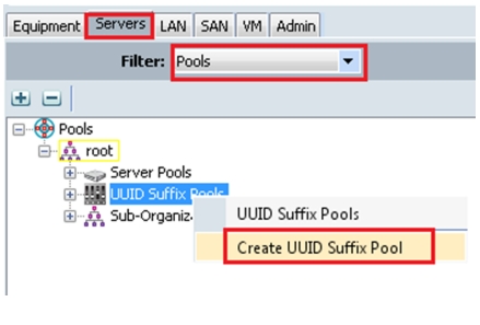
UUID Pool Creation
To create UUID pools, follow these steps:
1.
2.
3.
4.
Figure 24 Create UUID Pools
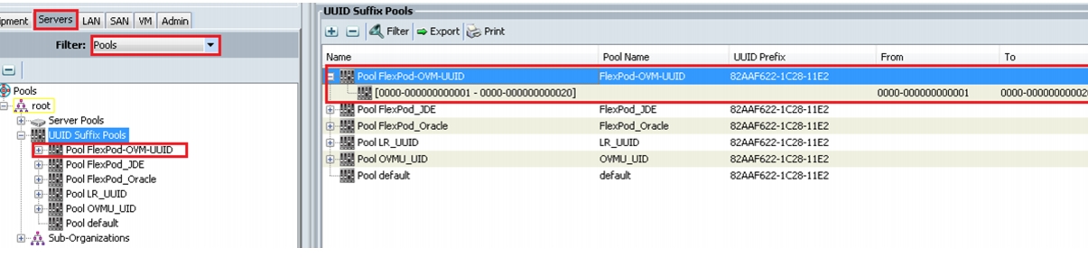
As shown in Figure 25, we have created Flexpod-OVM-UUID.
Figure 25 UUID Pool Summary
IP Pool and MAC Pool Creation
To create IP and MAC pools, follow these steps:
1.
2.
3.
4.
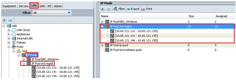
Figure 26 shows the creation of ext-mgmt IP pool.
Figure 26 Create IP Pool
To create MAC pools, follow these steps:
1.
2.
3.
4.
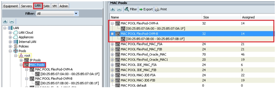
Figure 27 shows the creation of all the vNIC MAC pool addresses for Flexpod-OVM-A and Flexpod-OVM-B.
Figure 27 Create MAC Pool
Note
WWNN Pool and WWPN Pool Creation
To create WWNN and WWPN pools, follow these steps:
1.
2.
3.
4.
5.
6.
Note
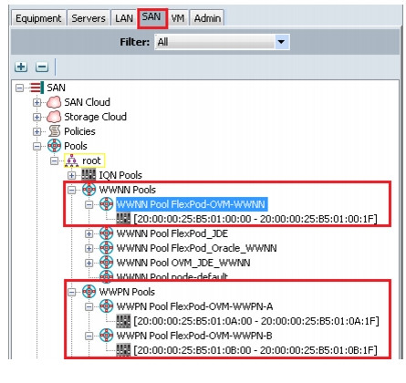
Figure 28 shows the creation of Flexpod-OVM WWNN, and Flexpod-OVM-A WWPN and Flexpod-OVM-B WWPN.
Figure 28 Create WWNN and WWPN Pool
Note
Set Jumbo Frames in Both the Cisco UCS Fabrics
To configure jumbo frames and enable quality of service in the Cisco UCS Fabric, follow these steps:
1.
2.
3.
4.
5.
6.
7.
Figure 29 Setting Jumbo Frame
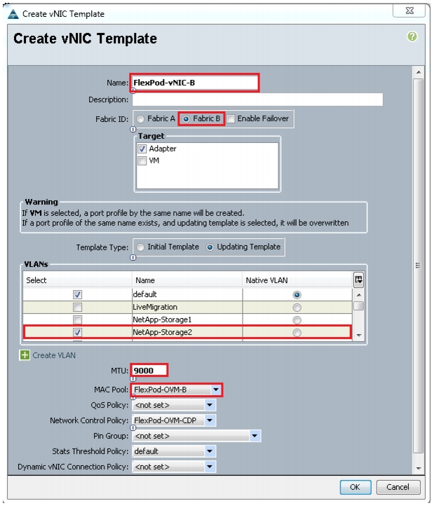
Configure vNIC and vHBA Templates
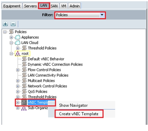
Create vNIC Templates
To create vNIC templates, follow these steps:
1.
2.
3.
4.
Figure 30 Create vNIC Template
Figure 31 and Figure 32 show vNIC templates for Fabric A and Fabric B.
Figure 31 vNIC Template for Fabric A
Figure 32 vNIC Template for Fabric B
Figure 33 shows the vNIC template summary.
Figure 33 vNIC Template Summary
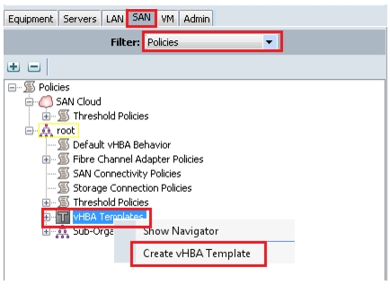
Create vHBA templates
To create vHBA templates, follow these steps:
1.
2.
3.
4.
Figure 34 Create vHBA Templates
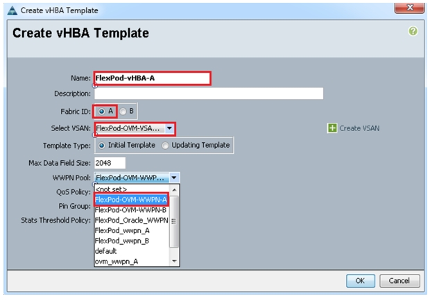
Figure 35 vHBA Template for Fabric A
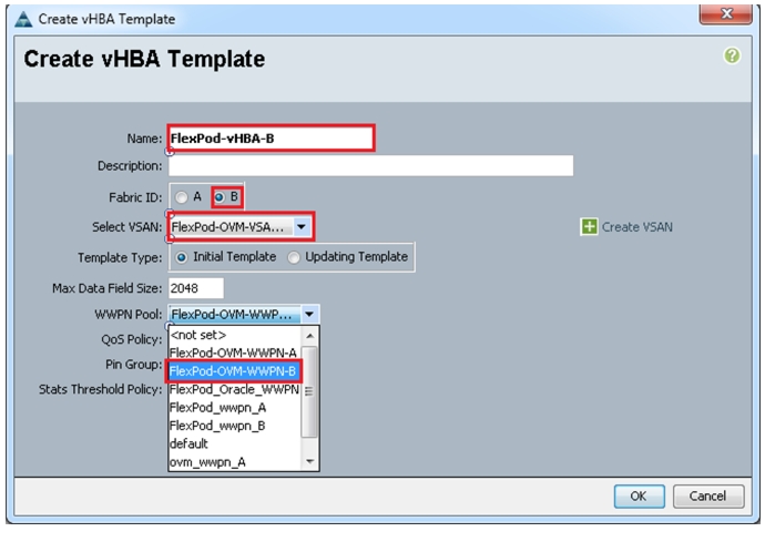
Figure 36 vHBA Template for Fabric B
Figure 35 and Figure 36 show two vHBA templates created, HBA Template Flexpod-vHBA-A, and HBA Template Flexpod-vHBA-B.
Next, we will configure Ethernet uplink port channels.
Configure Ethernet Uplink Port Channels
To configure Ethernet uplink port channels, follow these steps:
1.
2.
3.
4.
5.
6.
7.
8.
Note
Figure 37 and Figure 38 show the configuration of port channels for Fabric A and Fabric B.
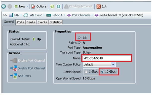
Figure 37 Configuring Port Channels
Figure 38 Fabric A Ethernet Port-Channel Details
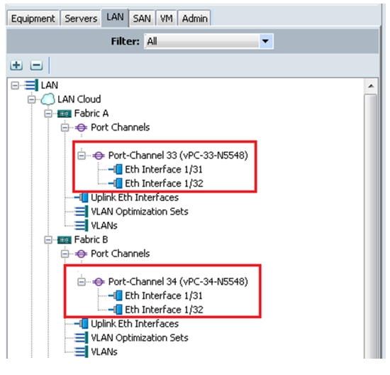
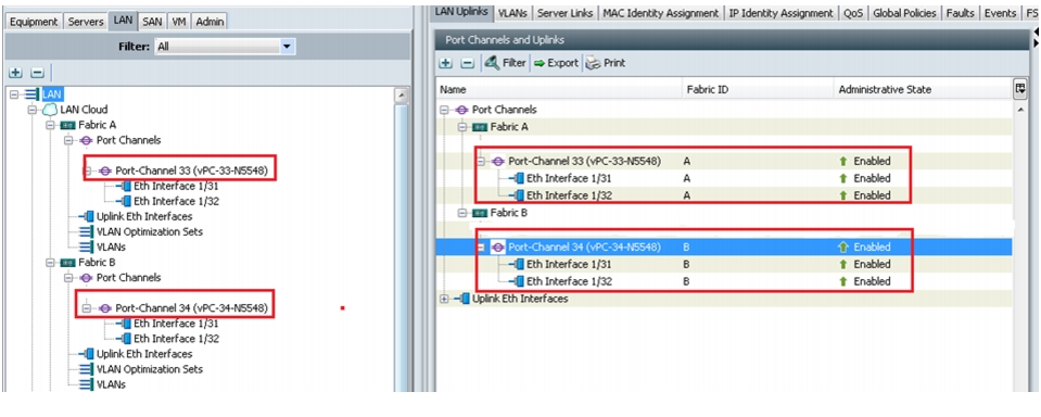
Figure 39 shows the configured port-channels on Fabric A and Fabric B.
Figure 39 Port-Channels on Fabric A and Fabric B
Once the above preparation steps are complete we are ready to create a service template from which the service profiles can be easily derived.
Create Local Disk Configuration Policy (Optional)
A local disk configuration for the Cisco UCS environment is necessary if the servers in the environment do not have a local disk.
Note
To create a local disk configuration policy, follow these steps:
1.
2.
3.
4.
5.
6.
7.
8.
Figure 40 Creating Local Disk Configuration Policy

Create FCoE Boot Policies
This procedure applies to a Cisco UCS environment in which the storage FCoE ports are configured in the following ways:
•
•
Two boot policies are configured in this procedure:
•
•
To create boot policies for the Cisco UCS environment, follow these steps:
1.
2.
3.
4.
5.
6.
7.
8.
9.
10.
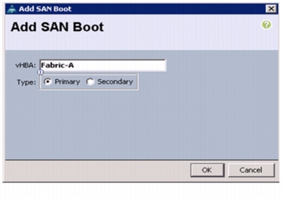
11.
Figure 41 Adding SAN Boot Initiator for Fabric A
12.
13.
14.

Note
15.
16.
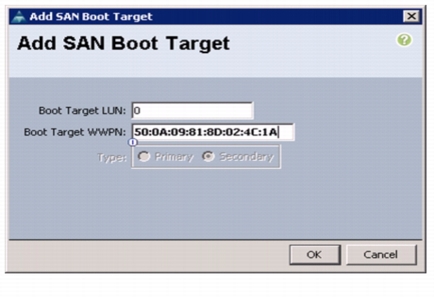
Figure 42 Adding SAN Boot Target for Fabric A

17.
18.
19.
Note
20.
Figure 43 Adding Secondary SAN Boot Target for Fabric A
21.
22.
23.
24.
Figure 44 Adding SAN Boot Initiator for Fabric B

25.
26.
27.
Note
28.
29.
Figure 45 Adding Primary SAN Boot Target for Fabric B
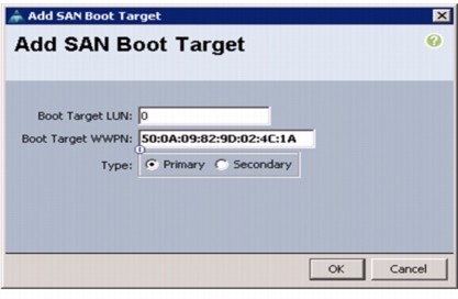
30.
31.
32.
Note
33.
Figure 46 Adding Secondary SAN Boot Target
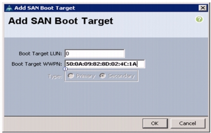
34.
35.
36.
37.
38.
39.
40.
41.
42.
43.
Figure 47 Adding SAN Boot Initiator for Fabric B

44.
45.
46.
Note
47.
48.
Figure 48 Adding Primary SAN Boot Target for Fabric B
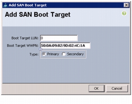
49.
50.
51.
Note
52.
Figure 49 Adding Secondary SAN Boot Target for Fabric B

53.
54.
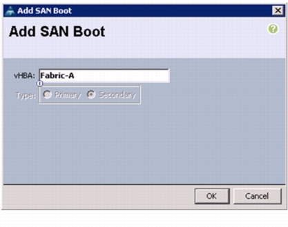
55.
56.
Figure 50 Adding SAN Boot for Fabric A
57.
58.
59.
Note
60.
61.
Figure 51 Adding Primary SAN Boot Target for Fabric A

62.
63.
64.
Note
65.
Figure 52 Adding Secondary SAN Boot Target for Fabric A

66.
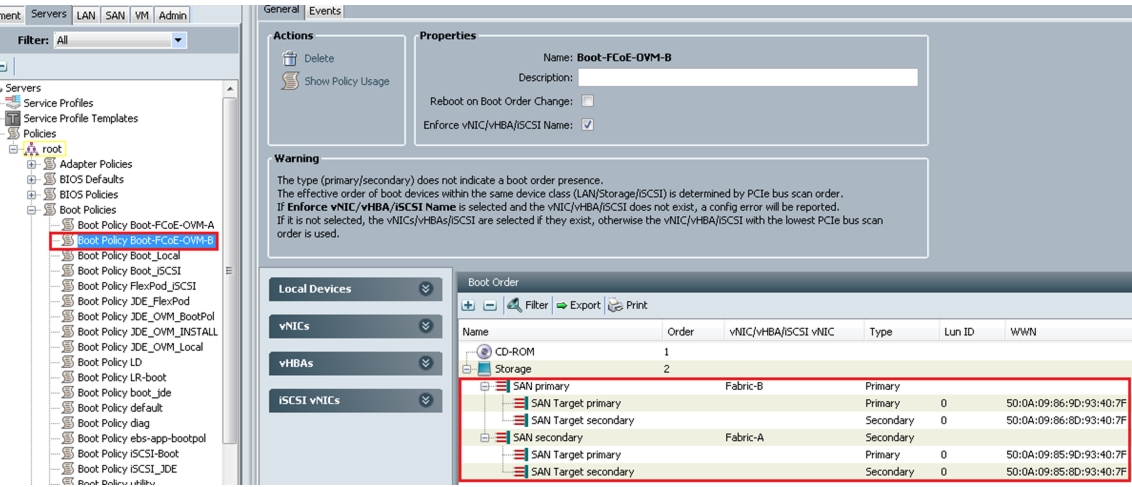
After creating the FCoE boot policies for Fabric A and Fabric B, you can view the boot order in the UCS Manager GUI. To view the boot order, navigate to Servers > Policies > Boot Policies. Select Boot Policy Boot-FCoE-OVM-A to view the boot order for Fabric A in the right pane of the UCS Manager. Similarly, select Boot Policy Boot-FCoE-OVM-B to view the boot order for Fabric B in the right pane of the UCS Manager. Figure 53 and Figure 54 show the boot policies for Fabric A and Fabric B respectively in the UCS Manager.
Figure 53 Boot Policy for Fabric A
Figure 54 Boot Policy for Fabric B
Service Profile creation and Association to UCS Blades
Service profile templates enable policy based server management that helps ensure consistent server resource provisioning suitable to meet predefined workload needs.
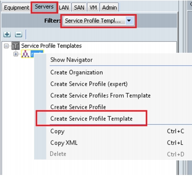
Create Service Profile Template
To create service profile template, follow these steps:
1.
2.
3.
4.
Figure 55 Create Service Profile Template
5.
6.
Figure 56 Creating Service Profile Template - Identify
7.
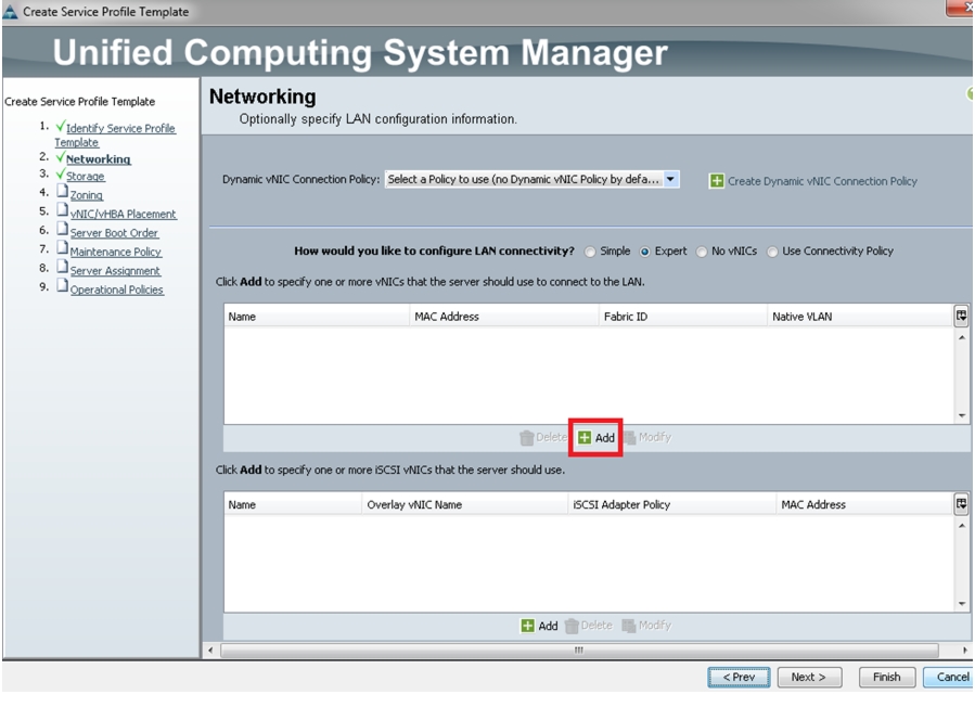
Figure 57 Creating Service Profile Template - Networking
8.
9.
10.
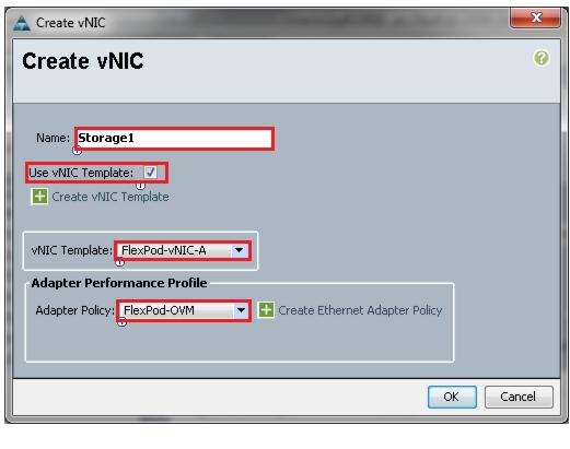
11.
Figure 58 Creating Service Profile Template - Create vNIC
12.
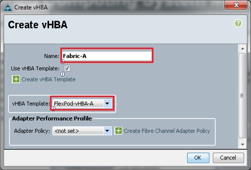
Once vNICs are created, we need to create vHBAs.
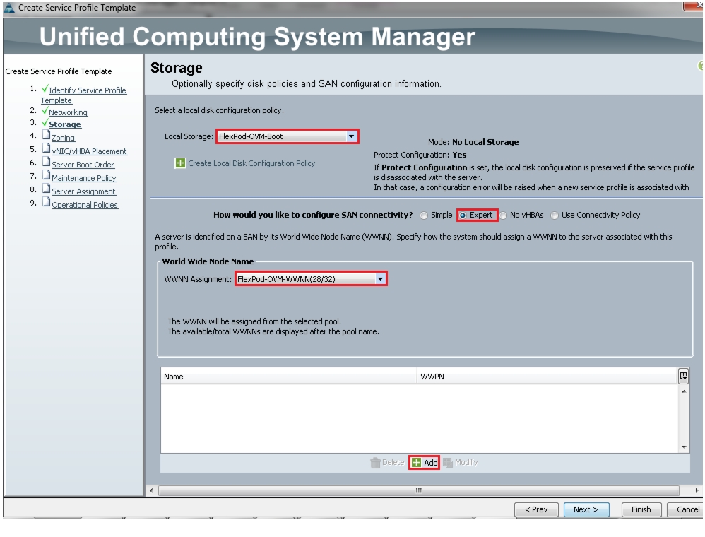
In the storage page, select expert mode, choose the WWNN pool created earlier and click Add to create vHBAs.
Figure 59 Creating Service Profile Template - Storage
We have created two vHBAs that are shown below.
•
•
Figure 60 Creating Service Profile Template - Create vHBA
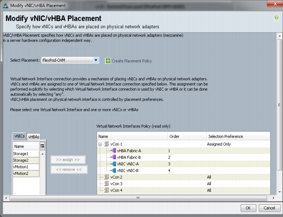
For this Flexpod configuration, we used Nexus 5548UP for zoning, so we will skip the zoning section and use default vNIC/vHBA placement.
Figure 61 Creating Service Profile Template - vNIC/vHBA Placement
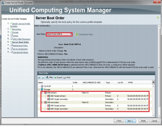
Server Boot Policy
In the Server Boot Order page, choose the Boot Policy we created for SAN boot and click Next.
Figure 62 Configure Server Boot Policy
The Maintenance and Assignment policies are kept at default in our configuration. However, they may vary from site to site depending on your work loads, best practices and policies.
Create Service Profiles from Service Profile Templates
To create service profiles from service profile templates, follow these steps:
1.
2.
3.
4.
Figure 63 Create Service profile from Service Profile template
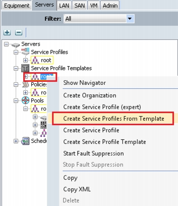
Figure 64 Create Service Profile from Service Profile Template
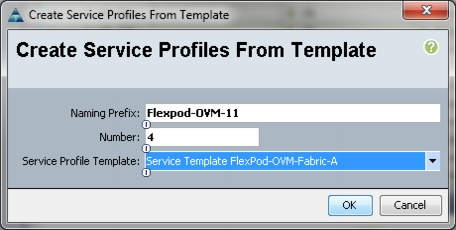
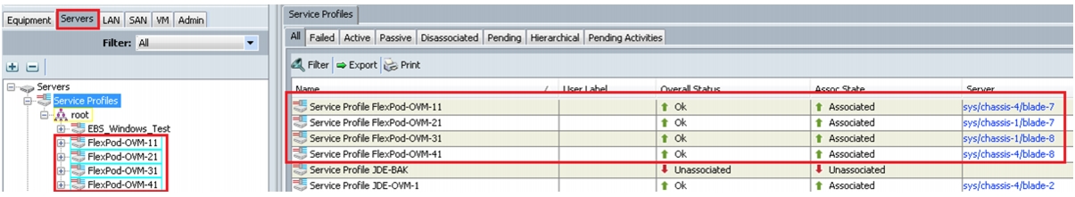
We have created four service profiles:
•
•
•
•
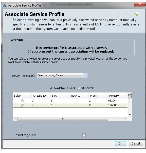
Associating Service Profile to Servers
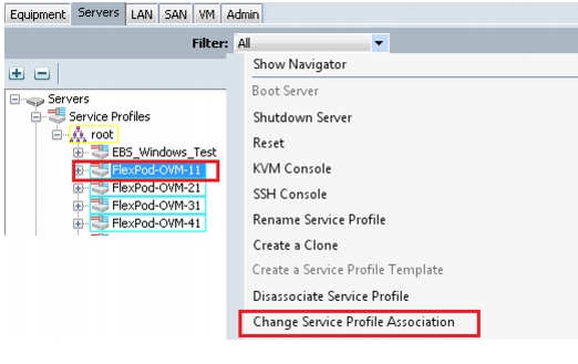
As service profiles are created now, we are ready to associate them to the servers. To associate service profiles to servers, follow these steps:
1.
2.
3.
Figure 65 Associating Service Profile to UCS Blade Servers
4.
5.
Figure 66 Changing Service Profile Association
6.
Figure 67 Associated Service Profiles Summary
Nexus 5548UP Configuration for FCoE Boot and NFS Data Access
Enable Licenses
Cisco Nexus A
To license the Cisco Nexus A switch on <<var_nexus_A_hostname>>, follow these steps:
1.
2.
config t
feature fcoe
feature npiv
feature lacp
feature vpc
Cisco Nexus B
To license the Cisco Nexus B switch on <<var_nexus_B_hostname>>, follow these steps:
1.
2.
config t
feature fcoe
feature npiv
feature lacp
feature vpc
Set Global Configurations
Cisco Nexus 5548 A and Cisco Nexus 5548 B
To set global configurations, follow these steps on both switches:
Run the following commands to set global configurations and jumbo frames in QoS:
1.
2.
conf t
spanning-tree port type network default
spanning-tree port type edge bpduguard default
port-channel load-balance ethernet source-dest-port
policy-map type network-qos jumbo
class type network-qos class-default
mtu 9216
exit
class type network-qos class-fcoe
pause no-drop
mtu 2158
exit
exit
system qos
service-policy type network-qos jumbo
exit
copy run start
Create VLANs
Cisco Nexus 5548 A and Cisco Nexus 5548 B
To create the necessary virtual local area networks (VLANs), follow these steps on both switches:
From the global configuration mode, run the following commands:
1.
2.
conf t
vlan 760
name Public-VLAN
exit
vlan 191
name Private-VLAN
exit
vlan 120
name Storage1-VLAN
exit
vlan 121
name Storage2-VLAN
exit
vlan 761
name LM-VLAN
exit
Add Individual Port Descriptions for Troubleshooting
Cisco Nexus 5548 A
To add individual port descriptions for troubleshooting activity and verification for switch A, follow these steps:
From the global configuration mode, run the following commands:
1.
2.
conf t
interface Eth1/1
description Nexus5k-B-Cluster-Interconnect
exit
interface Eth1/2
description Nexus5k-B-Cluster-Interconnect
exit
interface Eth1/3
description NetApp_Storage1:e5a
exit
interface Eth1/4
description NetApp_Storage2:e5a
exit
interface Eth1/5
description Fabric_Interconnect_A:1/31
exit
interface Eth1/6
description Fabric_Interconnect_B:1/31
exit
interface eth1/17
description FCoE_FI_A:1/29
exit
interface eth1/18
description FCoE_FI_A:1/30
exit
Cisco Nexus 5548 B
To add individual port descriptions for troubleshooting activity and verification for switch B, follow these steps:
From the global configuration mode, run the following commands:
1.
2.
conf t
interface Eth1/1
description Nexus5k-A-Cluster-Interconnect
exit
interface Eth1/2
description Nexus5k-A-Cluster-Interconnect
exit
interface Eth1/3
description NetApp_Storage1:e5b
exit
interface Eth1/4
description NetApp_Storage2:e5b
exit
interface Eth1/5
description Fabric_Interconnect_A:1/32
exit
interface Eth1/6
description Fabric_Interconnect_B:1/32
exit
interface eth1/17
description FCoE_FI_B:1/29
exit
interface eth1/18
description FCoE_FI_B:1/30
exit
Create Port Channels
Cisco Nexus 5548 A and Cisco Nexus 5548 B
To create the necessary port channels between devices, follow these steps on both switches:
From the global configuration mode, run the following commands:
1.
2.
conf t
interface Po1
description vPC peer-link
exit
interface Eth1/1-2
channel-group 1 mode active
no shutdown
exit
interface Po3
description NetApp_Storage1
exit
interface Eth1/3
channel-group 3 mode active
no shutdown
exit
interface Po4
description NetApp_Storage2
exit
interface Eth1/4
channel-group 4 mode active
no shutdown
exit
interface Po33
description Fabric_Interconnect_A
exit
interface Eth1/5
channel-group 33 mode active
no shutdown
exit
interface Po34
description Fabric_Interconnect_B
exit
interface Eth1/6
channel-group 34 mode active
no shutdown
exit
copy run start
Configure Port Channels
Cisco Nexus 5548 A and Cisco Nexus 5548 B
To configure the port channels, follow these steps on both switches:
From the global configuration mode, run the following commands:
1.
2.
conf t
interface Po1
switchport mode trunk
switchport trunk native vlan 1
switchport trunk allowed vlan 1,760,761,191,120,121
spanning-tree port type network
no shutdown
exit
interface Po3
switchport mode trunk
switchport trunk native vlan 1
switchport trunk allowed vlan 120,121
spanning-tree port type edge trunk
no shutdown
exit
interface Po4
switchport mode trunk
switchport trunk native vlan 1
switchport trunk allowed vlan 120,121
spanning-tree port type edge trunk
no shutdown
exit
interface Po33
switchport mode trunk
switchport trunk native vlan 1
switchport trunk allowed vlan 760,761,191,120,121
spanning-tree port type edge trunk
no shutdown
exit
interface Po34
switchport mode trunk
switchport trunk native vlan 1
switchport trunk allowed vlan 760,761,191,120,121
spanning-tree port type edge trunk
no shutdown
exit
copy run start
Configure Virtual Port Channels
Cisco Nexus 5548 A
To configure virtual port channels (vPCs) for switch A, follow these steps:
From the global configuration mode, run the following commands:
1.
2.
conf t
vpc domain 1
role priority 10
peer-keepalive destination <<var_nexus_B_mgmt0_ip>> source <<var_nexus_A_mgmt0_ip>>
auto-recovery
exit
interface Po1
vpc peer-link
exit
interface Po3
vpc 3
exit
interface Po4
vpc 4
exit
interface Po5
vpc 5
exit
interface Po6
vpc 6
exit
copy run start
Cisco Nexus 5548 B
To configure vPCs for switch B, follow these steps:
From the global configuration mode, run the following commands.
1.
2.
conf t
vpc domain 1
role priority 20
peer-keepalive destination <<var_nexus_A_mgmt0_ip>> source <<var_nexus_B_mgmt0_ip>>
auto-recovery
exit
interface Po1
vpc peer-link
exit
interface Po3
vpc 3
exit
interface Po4
vpc 4
exit
interface Po5
vpc 5
exit
interface Po6
vpc 6
exit
copy run start
Create VSANs, Assign and Enable Virtual Fibre Channel Ports
This procedure sets up Fibre Channel over Ethernet (FCoE) connections between the Cisco Nexus 5548 switches, the Cisco UCS Fabric Interconnects, and the NetApp storage systems.
Cisco Nexus 5548 A
To configure virtual storage area networks (VSANs), assign virtual Fibre Channel (vFC) ports, and enable vFC ports on switch A, follow these steps:
From the global configuration mode, run the following commands:
1.
2.
conf t
vlan 101
name FCoE_Fabric_A
fcoe vsan 101
exit
interface po3
switchport trunk allowed vlan add 101
exit
interface vfc3
switchport description NetApp_Storage1:5a
bind interface Eth1/3
switchport trunk allowed vsan 101
no shutdown
exit
interface po4
switchport trunk allowed vlan add 101
exit
interface vfc4
switchport description NetApp_Storage2:5a
bind interface Eth1/4
switchport trunk allowed vsan 101
no shutdown
exit
interface po35
description Fabric_Interconnect_A:FCoE
exit
interface Eth1/17-18
channel-group 35 mode active
exit
interface po35
switchport mode trunk
switchport trunk native vlan 1
switchport trunk allowed vlan 101
spanning-tree port type edge trunk
no shutdown
exit
interface vfc35
switchport description Fabric_Interconnect_A:FCoE
bind interface po35
switchport trunk allowed vsan 101
no shutdown
vsan database
vsan 101 name Fabric_A
vsan 101 interface vfc3
vsan 101 interface vfc4
vsan 101 interface vfc35
exit
Cisco Nexus 5548 B
To configure VSANs, assign vFC ports, and enable vFC ports on switch B, follow these steps:
From the global configuration mode, run the following commands:
1.
2.
conf t
vlan 102
name FCoE_Fabric_B
fcoe vsan 102
exit
interface po3
switchport trunk allowed vlan add 102
exit
interface vfc3
switchport description NetApp_Storage1:5b
bind interface Eth1/3
switchport trunk allowed vsan 102
no shutdown
exit
interface po4
switchport trunk allowed vlan add 102
exit
interface vfc4
switchport description NetApp_Storage2:5b
bind interface Eth1/4
switchport trunk allowed vsan 102
no shutdown
exit
interface po35
description Fabric_Interconnect_B:FCoE
exit
interface Eth1/17-18
channel-group 35 mode active
exit
interface po35
switchport mode trunk
switchport trunk native vlan 1
switchport trunk allowed vlan 102
spanning-tree port type edge trunk
no shutdown
exit
interface vfc35
switchport description Fabric_Interconnect_B:FCoE
bind interface po35
switchport trunk allowed vsan 102
no shutdown
vsan database
vsan 102 name Fabric_B
vsan 102 interface vfc3
vsan 102 interface vfc4
vsan 102 interface vfc35
exit
Create Device Aliases for FCoE Zoning
Cisco Nexus 5548 A
To configure device aliases and zones for the primary boot paths of switch A on <<var_nexus_A_hostname>>, follow these steps:
From the global configuration mode, run the following commands:
1.
2.
conf t
device-alias database
device-alias name Storage-FlexPod-A-5a pwwn 50:0a:09:85:9d:93:40:7f
device-alias name Storage-FlexPod-B-5a pwwn 50:0a:09:85:8d:93:40:7f
device-alias name OVM-Host-FlexPod-01-A pwwn 20:00:00:25:b5:01:0a:00
device-alias name OVM-Host-FlexPod-02-A pwwn 20:00:00:25:b5:01:0a:01
device-alias name OVM-Host-FlexPod-03-A pwwn 20:00:00:25:b5:01:0a:02
device-alias name OVM-Host-FlexPod-04-A pwwn 20:00:00:25:b5:01:0a:03
exit
device-alias commit
Cisco Nexus 5548 B
To configure device aliases and zones for the boot paths of switch B on <<var_nexus_B_hostname>>, follow these steps:
From the global configuration mode, run the following commands:
1.
2.
conf t
device-alias database
device-alias name Storage-FlexPod-A-5b pwwn 50:0a:09:86:9d:93:40:7f
device-alias name Storage-FlexPod-B-5b pwwn 50:0a:09:86:8d:93:40:7f
device-alias name OVM-Host-FlexPod-01-B pwwn 20:00:00:25:b5:01:0b:00
device-alias name OVM-Host-FlexPod-02-B pwwn 20:00:00:25:b5:01:0b:01
device-alias name OVM-Host-FlexPod-03-B pwwn 20:00:00:25:b5:01:0b:02
device-alias name OVM-Host-FlexPod-04-B pwwn 20:00:00:25:b5:01:0b:03
exit
device-alias commit
Create Zones
Cisco Nexus 5548 A
To create zones for the service profiles on switch A, follow these steps:
1.
Login as admin user.
Run the following commands:
conf t
zone name OVM-Host-FlexPod-01-A vsan 101
member device-alias OVM-Host-FlexPod-01-A
member device-alias Storage-FlexPod-A-5a
member device-alias Storage-FlexPod-B-5a
exit
zone name OVM-Host-FlexPod-02-A vsan 101
member device-alias OVM-Host-FlexPod-02-A
member device-alias Storage-FlexPod-A-5a
member device-alias Storage-FlexPod-B-5a
exit
zone name OVM-Host-FlexPod-03-A vsan 101
member device-alias OVM-Host-FlexPod-03-A
member device-alias Storage-FlexPod-A-5a
member device-alias Storage-FlexPod-B-5a
exit
zone name OVM-Host-FlexPod-04-A vsan 101
member device-alias OVM-Host-FlexPod-04-A
member device-alias Storage-FlexPod-A-5a
member device-alias Storage-FlexPod-B-5a
exit
2.
zoneset name FlexPod-OVM vsan 101
member OVM-Host-FlexPod-01-A
member OVM-Host-FlexPod-02-A
member OVM-Host-FlexPod-03-A
member OVM-Host-FlexPod-04-A
exit
3.
zoneset activate name FlexPod-OVM vsan 101
exit
copy run start
Cisco Nexus 5548 B
To create zones for the service profiles on switch B, follow these steps:
1.
Login as admin user.
Run the following commands:
zone name OVM-Host-FlexPod-01-B vsan 102
member device-alias OVM-Host-FlexPod-01-B
member device-alias Storage-FlexPod-A-5b
member device-alias Storage-FlexPod-B-5b
exit
zone name OVM-Host-FlexPod-02-B vsan 102
member device-alias OVM-Host-FlexPod-02-B
member device-alias Storage-FlexPod-A-5b
member device-alias Storage-FlexPod-B-5b
exit
zone name OVM-Host-FlexPod-03-B vsan 102
member device-alias OVM-Host-FlexPod-03-B
member device-alias Storage-FlexPod-A-5b
member device-alias Storage-FlexPod-B-5b
exit
zone name OVM-Host-FlexPod-04-B vsan 102
member device-alias OVM-Host-FlexPod-04-B
member device-alias Storage-FlexPod-A-5b
member device-alias Storage-FlexPod-B-5b
exit
2.
zoneset name FlexPod-OVM vsan 102
member OVM-Host-FlexPod-01-B
member OVM-Host-FlexPod-02-B
member OVM-Host-FlexPod-03-B
member OVM-Host-FlexPod-04-B
exit
3.
zoneset activate name FlexPod-OVM vsan 102
exit
copy run start
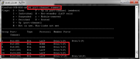
When configuring the Cisco Nexus 5548UP with vPCs, be sure that the status for all the vPCs are up for connected Ethernet ports by running the commands shown in Figure 68 from the CLI on the Cisco Nexus 5548UP Switch.
Figure 68 Port Channel Status on Cisco Nexus 5548UP
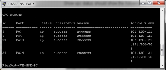
The command show vpc status should show the following for successful configuration.
Figure 69 Virtual PortChannel Status on Cisco Nexus 5548UP Fabric A switch
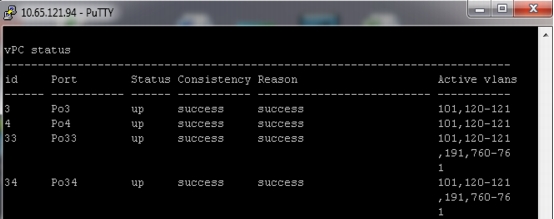
Figure 70 Virtual PortChannel Status on Cisco Nexus 5548UP on Fabric B Switch
NetApp Storage Configuration Overview
This section discusses the NetApp storage layout design considerations when deploying an Oracle Database 11g Release 2 RAC on Flexpod and Oracle VM 3.1.1.
Figure 71 depicts a high-level storage design overview of a NetApp FAS3270 HA storage system.
Figure 71 Design Overview of NetApp Storage Cluster

Table 3 shows the NetApp storage layout with volumes and LUNs created for various purposes.
Use the following commands to configure the NetApp storage systems to implement the storage layout design described here.
Storage Configuration for FCoE Boot
Create and Configure Aggregate, Volumes and Boot LUNs
NetApp FAS3270HA Controller A
1.
Create OS_Aggr_A with a RAID group size of 6 with 6 number of disks, and RAID_DP redundancy for hosting NetApp FlexVol volumes and LUNs, as shown in Table 3.
FlexPod-Oracle-A > aggr create OS_Aggr_A -t raid_dp -r 6 6
2.
FlexPod-Oracle-A > vol create OVM_OS_A OS_Aggr_A 500g
3.
FlexPod-Oracle-A > lun create -s 200g -t FlexPod-OVM-1
/vol/OVM_OS_A
4.
NetApp FAS3270HA Controller B
1.
FlexPod-Oracle-B > aggr create OS_Aggr_B -t raid_dp -r 6 6
2.
FlexPod-Oracle-B > vol create OVM_OS_B OS_Aggr_B 500g
3.
FlexPod-Oracle-B > lun create -s 200g -t FlexPod-OVM-2 /vol/ OVM_OS_B
4.
Create and Configure Initiator Group (igroup) and LUN mapping
NetApp FAS3270HA Controller A
1.
FlexPod-Oracle-A > igroup create -f -t xen FlexPod-OVM-A1 20:00:00:25:b5:01:0a:00 20:00:00:25:b5:01:0b:00
FlexPod-Oracle-A > lun map /vol/OVM_OS_A/FlexPod-OVM-1 FlexPod-OVM-A1 0
2.
NetApp FAS3270HA Controller B
1.
FlexPod-Oracle-B > igroup create -f -t xen FlexPod-OVM-B2 20:00:00:25:b5:01:0a:01 20:00:00:25:b5:01:0b:01
FlexPod-Oracle-B > lun map /vol/OVM_OS_B/FlexPod-OVM-3
FlexPod-OVM-B2 0
2.
Create and Configure Volumes and LUNs for Guest VMs
NetApp FAS3270HA Controller A
1.
FlexPod-Oracle-A > vol create GuestVM_OS_A OS_Aggr_A 1024g
2.
FlexPod-Oracle-A > lun create -s 1000g -t GuestVM_LUN_A
/vol/GuestVM_OS_A
NetApp FAS3270HA Controller B
1.
FlexPod-Oracle-B > vol create GuestVM_OS_B OS_Aggr_B 1024g
2.
FlexPod-Oracle-B > lun create -s 1000g -t GuestVM_LUN_B
/vol/GuestVM_OS_B
Create and Configure Initiator Group (igroup) and Mapping of LUN for Guest VM
NetApp FAS3270HA Controller A
Create Initiator group (Igroup) and map the LUN to all of the Oracle VM Server.
FlexPod-Oracle-A > igroup create -f -t xen FlexPod-GuestVM-A 20:00:00:25:b5:01:0a:03 20:00:00:25:b5:01:0b:03 20:00:00:25:b5:01:0a:02 20:00:00:25:b5:01:0b:02 20:00:00:25:b5:01:0a:01 20:00:00:25:b5:01:0b:01 20:00:00:25:b5:01:0a:00 20:00:00:25:b5:01:0b:00
FlexPod-Oracle-A > lun map /vol/GuestVM_OS_A/GuestVM_LUN_A FlexPod-GuestVM-A 0
NetApp FAS3270HA Controller B
Create Initiator group (Igroup) and map the LUN to all of the Oracle VM Server.
FlexPod-Oracle-B > igroup create -f -t xen FlexPod-GuestVM-B 20:00:00:25:b5:01:0a:03 20:00:00:25:b5:01:0b:03 20:00:00:25:b5:01:0a:02 20:00:00:25:b5:01:0b:02 20:00:00:25:b5:01:0a:01 20:00:00:25:b5:01:0b:01 20:00:00:25:b5:01:0a:00 20:00:00:25:b5:01:0b:00
FlexPod-Oracle-B > lun map /vol/GuestVM_OS_B/GuestVM_LUN_B FlexPod-GuestVM-B 0
Storage Configuration for NFS Storage Network
Create and Configure Aggregate, Volumes
NetApp FAS3270HA Controller A
1.
FlexPod-Oracle-A > aggr create DB_Aggr_A -t raid_dp -r 10 40
2.
FlexPod-Oracle-A > vol create DB_VOL_A DB_Aggr_A 3072g
FlexPod-Oracle-A > vol create DB_VOL_DSS_A DB_Aggr_A 2048g
FlexPod-Oracle-A > vol create LOG_VOL_A DB_Aggr_A 500g
FlexPod-Oracle-A > vol create LOG_VOL_DSS_A DB_Aggr_A 500g
FlexPod-Oracle-A > vol create OCR_VOTE_VOL DB_Aggr_A 20g
NetApp FAS3270HA Controller B
1.
FlexPod-Oracle-B > aggr create DB_Aggr_B -t raid_dp -r 10 40
2.
FlexPod-Oracle-B > vol create DB_VOL_B DB_Aggr_B 3072g
FlexPod-Oracle-B > vol create DB_VOL_DSS_B DB_Aggr_B 2048g
FlexPod-Oracle-B > vol create LOG_VOL_B DB_Aggr_B 500g
FlexPod-Oracle-B > vol create LOG_VOL_DSS_B DB_Aggr_B 500g
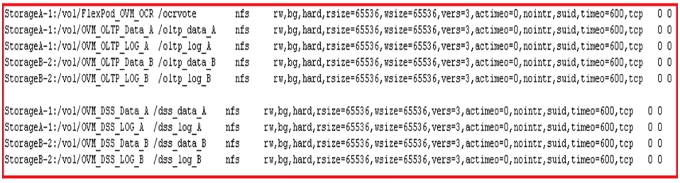
NFS export all the flexible volumes (data volumes, redo log volumes, and OCR and voting disk volumes) from both Controller A and Controller B, providing read/write access to the root user of all hosts created in the previous steps.
Create and Configure VIF Interface (Multimode)
Ensure NetApp multimode virtual interface (VIF) feature is enabled on NetApp storage systems on 10 Gigabit Ethernet ports (e5a and e5b) for NFS Storage access. We used the same VIF to access all the flexible volumes created to store Oracle Database files that use using the NFS protocol. Your best practices may vary depending upon setup.
VIF Configuration on Controller A
FlexPod-Oracle-A >ifgrp create multi VIF0-a -b ip e5a e5b
FlexPod-Oracle-A > vlan create VIF0-a 120 121
FlexPod-Oracle-A >ifconfig VIF0-a-120 120.191.1.5 netmask 255.255.255.0 mtusize 9000 partner VIF0-b-120
FlexPod-Oracle-A >ifconfig VIF0-a-121 121.191.1.5 netmask 255.255.255.0 mtusize 9000 partner VIF0-b-121
FlexPod-Oracle-A >ifconfig VIF0-a-120 up
FlexPod-Oracle-A >ifconfig VIF0-a-121 up
VIF Configuration on Controller B
FlexPod-Oracle-B>ifgrp create multi VIF0-b -b ip e5a e5b
FlexPod-Oracle-B> vlan create VIF0-b 120 121
FlexPod-Oracle-B>ifconfig VIF0-b-120 120.191.1.6 netmask 255.255.255.0 mtusize 9000 partner VIF0-a-120
FlexPod-Oracle-B>ifconfig VIF0-b-121 121.191.1.6 netmask 255.255.255.0 mtusize 9000 partner VIF0-a-121
FlexPod-Oracle-B>ifconfig VIF0-b-120 up
FlexPod-Oracle-B>ifconfig VIF0-b-121 up
Note
FlexPod-Oracle-A:: /etc/rc
#Regenerated by registry Thu Jan 10 09:37:52 GMT 2013
#Auto-generated by setup Mon Nov 5 02:37:43 GMT 2012
hostname FlexPod-Oracle-A
ifgrp create multi VIF0-a -b ip e5a e5b
vlan create VIF0-a 120 121
ifconfig e0M `hostname`-e0M flowcontrol full netmask 255.255.255.0
ifconfig e0a `hostname`-e0a mediatype auto flowcontrol full netmask 255.255.255.0
ifconfig VIF0-a-120 `hostname`-VIF0-a-120 netmask 255.255.255.0 partner VIF0-b-120 mtusize 9000 trusted wins up
ifconfig VIF0-a-121 `hostname`-VIF0-a-121 netmask 255.255.255.0 partner VIF0-b-121 mtusize 9000 trusted wins up
route add default 10.65.121.1 1
routed on
options dns.enable off
options nis.enable off
savecore
FlexPod-Oracle-B:: /etc/rc
#Auto-generated by setup Tue Jan 8 09:08:45 GMT 2013
hostname FlexPod-Oracle-B
ifgrp create multi VIF0-b -b ip e5a e5b
vlan create VIF0-b 120 121
ifconfig e0M `hostname`-e0M flowcontrol full netmask 255.255.255.0
ifconfig VIF0-b-120 `hostname`-VIF0-b-120 netmask 255.255.255.0 partner VIF0-a-120 mtusize 9000 trusted wins up
ifconfig VIF0-b-121 `hostname`-VIF0-b-121 netmask 255.255.255.0 partner VIF0-a-121 mtusize 9000 trusted wins up
route add default 10.65.121.1 1
routed on
options dns.enable off
options nis.enable off
savecore
Check the NetApp Configuration
Run the following commands to check the NetApp configuration:
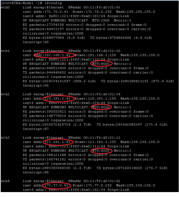
FlexPod-Oracle-A> vif status VIF0-a
FlexPod-Oracle-B> vif status VIF0-b
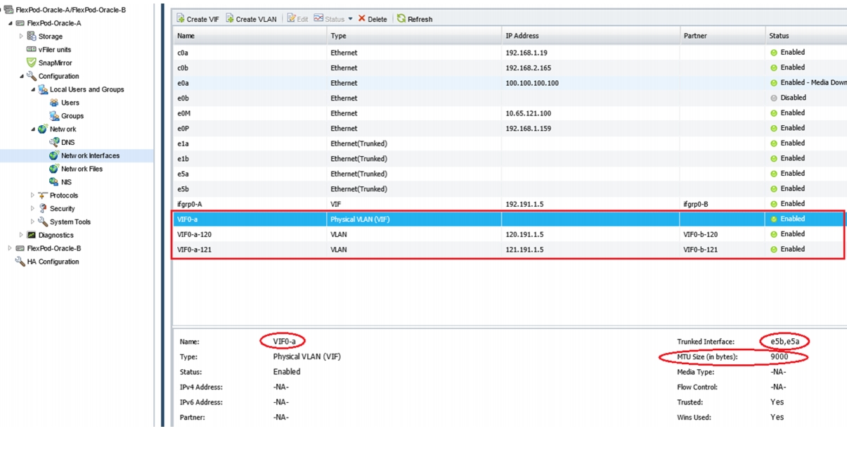
Ensure that the MTU is set to 9000 and that jumbo frames are enabled on the Cisco UCS static and dynamic vNICs and on the upstream Cisco Nexus 5548UP switches.
Figure 72 shows the virtual interface "VIF0-a" created with the MTU size set to 9000 and the trunk mode set to multiple, using two 10 Gigabit Ethernet ports (e5a and e5b) on NetApp storage Controller A. Verify the same on NetApp Controller B.
Figure 72 Virtual Interface (VIF) on NetApp Storage
This completes storage configuration. Next, we will review boot from FCoE details.
UCS Servers and Stateless Computing via FCoE Boot
Boot from FCoE Benefits
Booting from FCoE is another key feature which helps in moving towards stateless computing in which there is no static binding between a physical server and the OS / applications it is tasked to run. The OS is installed on a SAN LUN and boot from FCoE policy is applied to the service profile template or the service profile. If the service profile were to be moved to another server, the pwwn of the HBAs and the Boot from SAN (BFS) policy also moves along with it. The new server now takes the same exact character of the old server, providing the true unique stateless nature of the UCS Blade Server.
The key benefits of booting from the network:
•
Boot from FCoE alleviates the necessity for each server to have its own direct-attached disk, eliminating internal disks as a potential point of failure. Thin diskless servers also take up less facility space, require less power, and are generally less expensive because they have fewer hardware components.
•
All the boot information and production data stored on a local SAN can be replicated to a SAN at a remote disaster recovery site. If a disaster destroys functionality of the servers at the primary site, the remote site can take over with minimal downtime.
Recovery from server failures is simplified in a SAN environment. With the help of snapshots, mirrors of a failed server can be recovered quickly by booting from the original copy of its image. As a result, boot from SAN can greatly reduce the time required for server recovery.
•
A typical data center is highly redundant in nature - redundant paths, redundant disks and redundant storage controllers. When operating system images are stored on disks in the SAN, it supports high availability and eliminates the potential for mechanical failure of a local disk.
•
Businesses that experience temporary high production workloads can take advantage of SAN technologies to clone the boot image and distribute the image to multiple servers for rapid deployment. Such servers may only need to be in production for hours or days and can be readily removed when the production need has been met. Highly efficient deployment of boot images makes temporary server usage a cost effective endeavor.
With Boot from SAN, the image resides on a SAN LUN and the server communicates with the SAN through a host bus adapter (HBA). The HBAs BIOS contain the instructions that enable the server to find the boot disk. All the FC-capable Converged Network Adapter (CNA) cards supported on Cisco UCS B-series blade servers support Boot from SAN.
After power on self-test (POST), the server hardware component fetches the boot device that is designated as the boot device in the hardware BOIS settings. Once the hardware detects the boot device, it follows the regular boot process.
Quick Summary for Boot from SAN Configuration
At this time, we have completed following steps that are essential for Boot from SAN configuration.
•
•
•
At this time, you are ready to perform OS install. We will not cover steps to complete OS install in a FCoE boot configuration.
Oracle VM Server Install Steps and Recommendations
For this solution, we configured a 4-node Oracle Database 11g Release 2 RAC cluster using 4-Guest VM each created on one Oracle VM Server. There are four Cisco B200 M3 servers used boot from SAN to enable stateless computing in case if a need arises to replace/swap the server using UCS unique service profile capabilities. While OS boot is using FCoE, the databases and grid infrastructure components are configured to use NFS protocol on the NetApp storage. Oracle VM Server 3.1.1 with Patch 819 (Oracle VM Server 3.1.1.819) is installed on each server.
Note
This patch will allow you to enable jumbo frames (MTU= 9000) on Ethernet ports of Oracle VM server as well as Guest VM. Without this patch the Oracle VM server as well as guest VM reboots, when you set MTU size 9000 on Ethernet ports of Oracle VM server and guest VM.
Following table summarizes hardware and software configuration details.
Here we show few major steps to Install Oracle VM Server in one Cisco UCS blade server B200M3 using FCoE boot. There is no local disks available in Cisco UCS blade server B200M3.
1.
Note
Figure 73 OVS ISO attached to as Virtual Media to KVM Console
2.
Figure 74 Starting the Installation
3.
Figure 75 NetApp LUN Discovered
4.
Figure 76 Ready for Installation
Figure 77 OVS Installation Status
Figure 78 shows the finish of Oracle VM Server Installation after we provide all the required values during the Installation like configure the management Ethernet interface with appropriate ip. Ensure to verify the displayed MAC address with the static vNIC ethernet interface created on Service Profile for public/ management access.
Figure 78 Completion of Installation
Use the above Oracle VM Server Installation steps to complete the Installation for all the four Cisco UCS B200M3 Server.
Oracle VM Server Network Architecture
Figure 79 shows the Network Architecture of each Oracle VM Server.
Figure 79 Oracle VM Server Network Architecture
Oracle VM Manager Installation
Oracle VM Manager is installed as a production level; this is the preferred installation type, with options for selecting Oracle SE or EE database as the location for the Oracle VM Manager repository, as well as setting individual passwords for each component. Ensure that Oracle SE Database is installed; prior to installing Oracle VM Manager. Please follow the steps below to successfully install OVM Manager.
1.
2.
3.
4.
5.
[root@ovmmanager ovmmanager]# ./runInstaller.sh
Oracle VM Manager Release 3.1.1 Installer
Oracle VM Manager Installer log file:
/tmp/install-2013-06-10-164951.log
Please select an installation type:
Demo
Production
Uninstall
Help
Select Number (1-4): 2
Starting production installation ...
Verifying installation prerequisites ...
Oracle Database Repository
==========================
Use an existing Oracle database
Enter the Oracle Database hostname [localhost]: ovmmanager
Enter the Oracle Database System ID (SID) [XE]: orcl
Enter the Oracle Database SYSTEM password:
Enter the Oracle Database listener port [1521]: 1521
Enter the Oracle VM Manager database schema [ovs]: ovs1
Enter the Oracle VM Manager database schema password:
Invalid password.
Passwords need to be between 8 and 16 characters in length.
Passwords must contain at least 1 lower case and 1 upper case letter.
Passwords must contain at least 1 numeric value.
Enter the Oracle VM Manager database schema password:
Enter the Oracle VM Manager database schema password (confirm):
Oracle Weblogic Server 11g
==========================
Enter the Oracle WebLogic Server 11g user [weblogic]:
Enter the Oracle WebLogic Server 11g user password:
Enter the Oracle WebLogic Server 11g user password (confirm):
Passwords do not match
Enter the Oracle WebLogic Server 11g user password:
Enter the Oracle WebLogic Server 11g user password (confirm):
Oracle VM Manager application
=============================
Enter the username for the Oracle VM Manager administration user [admin]:
Enter the admin user password:
Enter the admin user password (confirm):
Verifying configuration ...
Start installing the configured components:
1: Continue
2: Abort
Select Number (1-2): 1
Step 1 of 9 : Database ...
Installing Database ...
Database installation skipped ...
Step 2 of 9 : Java ...
Installing Java ...
Step 3 of 9 : Database Schema ...
Creating database schema 'ovs1' ...
Step 4 of 9 : WebLogic ...
Retrieving Oracle WebLogic Server 11g ...
Installing Oracle WebLogic Server 11g ...
Step 5 of 9 : ADF ...
Retrieving Oracle Application Development Framework (ADF) ...
Unzipping Oracle ADF ...
Installing Oracle ADF ...
Installing Oracle ADF Patch...
Step 6 of 9 : Oracle VM ...
Retrieving Oracle VM Manager Application ...
Extracting Oracle VM Manager Application ...
Installing Oracle VM Manager Core ...
Step 7 of 9 : Domain creation ...
Creating Oracle WebLogic Server domain ...
Starting Oracle WebLogic Server 11g ...
Configuring data source 'OVMDS' ...
Creating Oracle VM Manager user 'admin' ...
Step 8 of 9 : Deploy ...
Deploying Oracle VM Manager Core container ...
Deploying Oracle VM Manager UI Console ...
Deploying Oracle VM Manager Help ...
Enabling HTTPS ...
Granting ovm-admin role to user 'admin' ...
Step 9 of 9 : Oracle VM Manager Shell ...
Retrieving Oracle VM Manager Shell & API ...
Extracting Oracle VM Manager Shell & API ...
Installing Oracle VM Manager Shell & API ...
Retrieving Oracle VM Manager Upgrade tool ...
Extracting Oracle VM Manager Upgrade tool ...
Installing Oracle VM Manager Upgrade tool ...
Copying Oracle VM Manager shell to '/usr/bin/ovm_shell.sh' ...
Installing ovm_admin.sh in '/u01/app/oracle/ovm-manager-3/bin' ...
Installing ovm_upgrade.sh in '/u01/app/oracle/ovm-manager-3/bin' ...
Enabling Oracle VM Manager service ...
Shutting down Oracle VM Manager instance ...
Restarting Oracle VM Manager instance ...
Waiting 15 seconds for the application to initialize ...
Oracle VM Manager is running ...
Oracle VM Manager installed.
Please wait while WebLogic configures the applications... This can take up to 5 minutes.
Installation Summary
--------------------
Database configuration:
Database host name : ovmmanager
Database instance name (SID): orcl
Database listener port : 1521
Application Express port : None
Oracle VM Manager schema : ovs1
Weblogic Server configuration:
Administration username : weblogic
Oracle VM Manager configuration:
Username : admin
Core management port : 54321
UUID : 0004fb00000100000a5c59c7f7487ffe
Passwords:
There are no default passwords for any users. The passwords to use for Oracle VM Manager, Oracle Database 11g XE, and Oracle WebLogic Server have been set by you during this installation. In the case of a default install, all the passwords are the same.
Oracle VM Manager UI:
http://ovmmanager:7001/ovm/console
https://ovmmanager:7002/ovm/console
Log in with the user 'admin', and the password you set during the installation.
Please note that you need to install tightvnc-java on this computer to access a virtual machine's console.
For more information about Oracle Virtualization, please visit:
http://www.oracle.com/virtualization/
Oracle VM Manager installation complete.
Please remove configuration file /tmp/ovm_configzFYrq_.
Post Oracle VM Manager installation, apply Oracle VM Manager 3.1.1 Patch Update (Build 365) [ID 1530546.1]. This would help in resolution of time out issues on creation of ovm 3.1.1.
Oracle VM Server Configuration Using Oracle VM Manager
Some of the important steps to configure Oracle VM environment are elaborated in the figure below.
Figure 80 Oracle VM Server Configuration and Guest VM Creation Steps
1.
Figure 81 Oracle VM Servers Listed in the VM Manager
2.
Figure 82 Network Configuration
3.
Figure 83 Setting MTU Size
4.
Figure 84 Cluster Pool
Figure 85 Status of all the Servers
5.
Figure 86 Storage Repository
6.
Figure 87 Guest VMs Details
7.
Figure 88 Guest VMs Network Ports
8.
Figure 89 Disk Configuration for Oracle RAC Node
Once the Guest VMs are created we can proceed to Installation of Oracle Linux 6.2 on each of the Guest VMs.
Oracle Linux Installation
Some of the important steps during Oracle Linux installation are:
1.
Figure 90 http Setup for PVM Installation
2.
Figure 91 Text Mode Selection
3.
Figure 92 Selecting Virtual Disk
4.
Figure 93 Confirm OS Installation
Some of the important steps executed post Oracle Linux installation are detailed below:
1.
2.
3.
Figure 94 MTU Size 9000 and IP Configured for all Ethernet Ports
Once OS installation is complete, we can proceed to the Oracle Grid install in next section.
Oracle Database 11g Release 2 Grid Infrastructure with RAC Option Deployment
This section describes high level steps for Oracle Database 11g Release 2 RAC install. Prior to Grid and database install, verify all the prerequisites are completed. You can install Oracle validated RPM that will ensure most of the OS prerequisites are met before Oracle Grid install. We will not cover step-by-step install for Oracle Grid in this document but will provide partial summary of details that is relevant. As a best practice recommended from Oracle, ready-to-go Oracle VM Templates for Oracle RAC can be downloaded from Oracle Software Delivery Cloud for faster deployment
Use the following Oracle document for pre-installation tasks, such as setting up the kernel parameters, RPM packages, user creation, and so on.
(http://download.oracle.com/docs/cd/E11882_01/install.112/e10812/prelinux.htm#BABHJHCJ)
1.
groupadd -g 1000 oinstall
groupadd -g 1200 dba
useradd -u 2000 -g oinstall -G dba grid
passwd grid
useradd -u 1100 -g oinstall -G dba oracle
passwd oracle
2.
mkdir -p /u01/app/11.2.0/grid
mkdir -p /u01/app/oracle
mkdir /oltp_data_A
mkdir /oltp_data_B
mkdir /dss_data_A
mkdir /dss_data_B
mkdir /oltp_log_A
mkdir /oltp_log_B
mkdir /dss_log_A
mkdir /dss_log_B
mkdir /ocrvote
chown -R oracle:oinstall /u01/app/oracle / oltp_data_A /oltp_data_B /dss_data_A /dss_data_B /oltp_log_A /oltp_log_B /dss_log_A /dss_log_B
chmod -R 775 /u01/app/oracle / oltp_data_A /oltp_data_B /dss_data_A /dss_data_B /oltp_log_A /oltp_log_B /dss_log_A /dss_log_B
chown -R grid:oinstall /u01/app /ocrvote
chmod -R 775 /u01/app /ocrvote
In this test case, we used local directory for Grid Installation and Database binary Installation. As an alternate. these binaries can be installed in a shared directory on NFS volumes.
Following table summarizes NFS Volumes mapping with mount points for each Oracle RAC node.
3.
Note
Here is sample output from mount command on Node 1:
[root@orarac1 ~]# mount
To determine the proper mount options for different file systems of Oracle 11g Release 2, see:
https://kb.netapp.com/support/index?page=content&id=3010189&actp=search&viewlocale=en_US&searchid
Note
4.
5.
6.
Login as "grid" user from any one node and create the following raw files
dd if=/dev/zero of=/ocrvote/ocr/ocr1 bs=1m count=1024
dd if=/dev/zero of=/ocrvote/ocr/ocr2 bs=1m count=1024
dd if=/dev/zero of=/ocrvote/ocr/ocr3 bs=1m count=1024
dd if=/dev/zero of=/ocrvote/vote/vote1 bs=1m count=1024
dd if=/dev/zero of=/ocrvote/vote/vote2 bs=1m count=1024
dd if=/dev/zero of=/ocrvote/vote/vote3 bs=1m count=1024
7.
Note
8.
Note
9.
Hugepages is a method to have larger page size that is useful for working with very large memory. For Oracle Databases, using HugePages reduces the operating system maintenance of page states, and increases Translation Lookaside Buffer (TLB) hit ratio.
Advantages of HugePages
•
•
•
•
•
For our configuration, we used hugepages for both OLTP and DSS workloads. Please refer to Oracle metalink document 361323.1 for hugepages configuration details.
Once hugepages are configured, You are now ready to install Oracle Grid Infrastructure and the Oracle Database 11g Release 2 including Oracle RAC.
Installing Oracle RAC 11g Release 2
It is not within the scope of this document to include the specifics of an Oracle RAC installation; you should refer to the Oracle installation documentation for specific installation instructions for your Environment. For best practices recommended by Oracle. See:
•
•
To install Oracle, follow these steps:
1.
2.
Figure 95 Oracle Grid Infrastructure - Selecting Configuration Option
Figure 96 Oracle Grid Infrastructure - Grid Plug and Play
Figure 97 Oracle Grid Infrastructure - Network Interface Usage
3.
Figure 98 Oracle Grid Infrastructure - Setting Storage Option
Figure 99 Oracle Grid Infrastructure - Setting OCR Storage Option
Figure 100 Oracle Grid Infrastructure - Setting Voting Disk Storage Option
Figure 101 Oracle Grid Infrastructure - Performance Prerequisite Checks
Figure 102 Oracle Grid Infrastructure - Summary
4.
5.
http://www.oracle.com/pls/db112/to_toc?pathname=install.112/e10813/toc.htm
6.
Table 6 shows the configuration of OLTP and DSS Databases:
7.
For improved NFS performance, Oracle recommends using the Direct NFS Client shipped with Oracle 11g. The direct NFS client looks for NFS details in the following locations:
–
–
–
In RAC configuration with Direct NFS, the oranfstab must be configured on all the nodes. Here is oranfstab configuration from RAC node 1.
[oracle@orarac1 dbs]$ vi oranfstab
server: 120.191.1.5
path: 120.191.1.5
path: 121.191.1.5
server: 121.191.1.6
path: 121.191.1.6
path: 120.191.1.6
export:/ocrvote mount:/vol/FlexPod_OVM_OCR
export:/oltp_data_A mount:/vol/OVM_OLTP_Data_A
export:/oltp_log_A mount:/vol/OVM_OLTP_Data_A
export:/oltp_data_B mount:/vol/OVM_OLTP_Data_B
export:/oltp_log_B mount:/vol/OVM_OLTP_LOG_B
export:/dss_data_A mount:/vol/OVM_DSS_Data_A
export:/dss_log_A mount:/vol/OVM_DSS_LOG_A
export:/dss_data_B mount:/vol/OVM_DSS_Data_B
export:/dss_log_B mount:/vol/OVM_DSS_LOG_B
Since the NFS mount point details were defined in the "/etc/fstab", and therefore the "/etc/mtab" file also, there is no need to configure any extra connection details. When setting up your NFS mounts, reference the Oracle documentation for guidance on what types of data can/cannot be accessed via Direct NFS Client. For the client to work we need to switch the libodm11.so library for the libnfsodm11.so library, as shown below.
srvctl stop database -d OLTPORCL
srvctl stop database -d dssorcl
cd $ORACLE_HOME/lib
mv libodm11.so libodm11.so_stub
ln -s libnfsodm11.so libodm11.so
srvctl start database -d OLTPORCL
srvctl start database -d dssorcl
Note
With the configuration complete, you can see the direct NFS client usage via the following views:
–
–
–
–
Here is an example from OLTP database configuration
SQL> select SVRNAME, DIRNAME from v$DNFS_SERVERS;
SVRNAME DIRNAME
------------ ------------
StorageA-1 /vol/OVM_OLTP_Data_A
StorageB-2 /vol/OVM_OLTP_Data_B
StorageA-1 /vol/OVM_OLTP_LOG_A
StorageB-2 /vol/OVM_OLTP_LOG_B
Note
Workloads and Database Configuration
We used Swingbench for workload testing. Swingbench is simple to use, free, Java based tool to generate database workload and perform stress testing using different benchmarks in Oracle database environments. Swingbench provides four separate benchmarks, namely, Order Entry, Sales History, Calling Circle, and Stress Test. For the tests described in this paper, Swingbench Order Entry benchmark was used for OLTP workload testing and the Sales History benchmark was used for the DSS workload testing. The Order Entry benchmark is based on SOE schema and is similar to TPC-C by types of transactions. The workload uses a very balanced read/write ratio around 60/40 and can be designed to run continuously and test the performance of a typical Order Entry workload against a small set of tables, producing contention for database resources. The Sales History benchmark is based on the SH schema and is TPC-H kind. The workload is query (read) centric and is designed to test the performance of the queries against large tables.
As discussed in previous section, two independent databases were created earlier for Oracle Swingbench OLTP and DSS workloads. Next step is to pre create the order entry and sales history schema for OLTP and DSS workload. Swingbench Order Entry (OLTP) workload uses SOE tablespace and Sales History workload uses SH tablespaces. We pre created these schemas in order to associate multiple datafiles with tablespaces and also evenly distributing them across two storage controllers. For our setup, we created 90 datafiles for SOE tablespace with odd number files for storage controller A and even number of files for storage controller B. In the same way, we used 50 datafiles for Sales history workload and evenly distributed them across both the storage controllers. Once schema for workloads was created, we populated both databases with Swingbench datagenerator as shown below.
OLTP Database
The OLTP database was populated with the following data:
[oracle@orarac1 ~]$ sqlplus soe/soe
SQL*Plus: Release 11.2.0.3.0 Production on Wed Mar 27 12:02:01 2013
Copyright (c) 1982, 2011, Oracle. All rights reserved.
Connected to:
Oracle Database 11g Enterprise Edition Release 11.2.0.3.0 - 64bit Production
With the Partitioning, Real Application Clusters, Oracle Label Security, OLAP,
Data Mining, Oracle Database Vault and Real Application Testing options
SQL> select table_name, num_rows from user_tables;
TABLE_NAME NUM_ROWS
------------------------------ ----------
CUSTOMERS 2300000000
WAREHOUSES 1000
ORDER_ITEMS 7762397098
ORDERS 2822094567
INVENTORIES 900524
PRODUCT_INFORMATION 1000
LOGON 1283813440
PRODUCT_DESCRIPTIONS 1000
ORDERENTRY_METADATA 4
DSS (Sales History) Database
The DSS database was populated with the following data:
[oracle@orarac1 ~]$ sqlplus sh/sh
SQL*Plus: Release 11.2.0.3.0 Production on Wed Mar 27 12:11:45 2013
Copyright (c) 1982, 2011, Oracle. All rights reserved.
Connected to:
Oracle Database 11g Enterprise Edition Release 11.2.0.3.0 - 64bit Production
With the Partitioning, Real Application Clusters, Oracle Label Security, OLAP,
Data Mining, Oracle Database Vault and Real Application Testing options
SQL> select table_name, num_rows from user_tables;
TABLE_NAME NUM_ROWS
------------------------------ ----------
CHANNELS 5
COUNTRIES 23
CUSTOMERS 1300000000
PROMOTIONS 503
PRODUCTS 72
SUPPLEMENTARY_DEMOGRAPHICS 1300000000
SALES 6500000000
TIMES 6209
As typically encountered in the real world deployments, we tested scalability and stress related scenarios that ran on current 4-node Oracle RAC cluster configuration.
1.
2.
3.
Performance Data from the Tests
Once the databases were created, we started out with OLTP database calibration about number of users and database configuration. For Order Entry workload, we used 48GB SGA and ensured that the hugepages were in use. Each OLTP scalability test was run for at least 12 hours and we ensured that the results are consistent for the duration of full run.
OLTP Workload
For OLTP workloads, the common measurement metrics are Transactions Per Minute (TPM), users scalability with IOPs and CPU utilization. Here are the scalability charts for Order Entry workload.
Figure 103 OLTP Transactions
For OLTP TPM tests, we ran tests with 50, 100, 200 and 400 users across 4-node cluster. During tests, we validated that Oracle SCAN listener fairly and evenly distributed the load balanced users across all the 4 nodes of the cluster. We also observed appropriate scalability in TPMs as number or users across clusters increased. Next graph shows increased IO and scalability as number of users across increased.
Figure 104 OLTP IOPs and Scalability
As indicated in the graph, we observed about 26850 IO/Sec across 4-node cluster. The Oracle AWR report below also summarizes Physical Reads/Sec and Physical Writes/Sec per instance. During OLTP tests, we observed some resource utilization variations due to random nature of the workload as depicted by 200 users IOPs. We ran each test multiple times to ensure consistent numbers that are presented in this solution.
The table below shows interconnect traffic for the 4-node Oracle RAC cluster during 400 user run. The average interconnect traffic was 215 MB/Sec for the duration of the run.
The chart below indicates cluster CPU utilization as the number of users scale from 12 users/node to 100 users/node.
Figure 105 CPU Utilization
DSS Workload
DSS workloads are generally sequential in nature, read intensive and exercise large IO size. DSS workloads run a small number of users that typically exercise extremely complex queries that run for hours. For our tests, we ran Swingbench Sales history workload with 12 users. The charts below show DSS workload results.
Figure 106 DSS Workload - I/O Bandwidth
For 24 hour DSS workload test, we observed total IO bandwidth ranging between 1.5 GBytes/Sec and 1.7 GBytes/Sec. As indicated on the charts, the IO was also evenly distributed across both NetApp FAS storage controllers and we did not observe any significant dips in performance and IO bandwidth for a sustained period of time.
Mixed Workload
Next test is to run both OLTP and DSS workloads simultaneously. This test will ensure that configuration in this test is able to sustain small random queries presented via OLTP along with large and sequential transactions submitted via DSS workload. We ran the tests for 24 hours. Here are the results.
Figure 107 Mixed Workload - I/O Bandwidth
For mixed workloads running for 24 hours, we observed approximately 1.4 GBytes/Sec. IO bandwidth. The OLTP transactions also averaged between 220K and 230K transactions per minute.
Figure 108 Mixed Workload - TPM
Destructive and Hardware failover Tests
The goal of these tests is to ensure that reference architecture withstands commonly occurring failures either due to unexpected crashes, hardware failures or human errors. We conducted many hardware, software (process kills) and OS specific failures that simulate real world scenarios under stress conditions. In the destructive testing, we also demonstrate unique failover capabilities of Cisco VIC 1240 adapter. We have highlighted some of those test cases as below.
Figure 109 Flexpod Test Details
Conclusion
FlexPod is built on leading computing, networking, storage, and infrastructure software components. With Flexpod based solution, customers can leverage a secure, integrated, and optimized stack that includes compute, network and storage resources that are sized, configured and deployed as a fully tested unit running industry standard applications such as Oracle Database 11g RAC over D-NFS (Direct NFS). The following factors make the combination of Cisco UCS with NetApp storage so powerful for Oracle environments:
•
•
•
The availability of Oracle VM overcomes this obstacle. Providing software based virtualization infrastructure (Oracle VM) and the market leading high availability solution Oracle Real Application Clusters (RAC), Oracle now offers a highly available, grid-ready virtualization solution for your data center, combining all the benefits of a fully virtualized environment. The combination of Oracle VM and Oracle RAC enables a better server consolidation (RAC databases with under utilized CPU resources or peaky CPU utilization can often benefit from consolidation with other workloads using server virtualization) sub-capacity licensing, and rapid provisioning. Following are the major advantages of using Oracle RAC on Oracle VM.
•
•
•
•
As a result, customers can achieve dramatic cost savings when leveraging Ethernet based products plus deploy any application on a scalable Shared IT infrastructure built on Cisco and NetApp technologies. Finally, FlexPod™, jointly developed by NetApp and Cisco, is a flexible infrastructure platform composed of pre-sized storage, networking, and server components. It's designed to ease your IT transformation and operational challenges with maximum efficiency and minimal risk.
FlexPod differs from other solutions by providing:
•
•
•
•
•
Appendix
Appendix A: Nexus 5548UP Configuration
Here is an example shows Nexus 5548 Fabric Zoning Configuration for all the Oracle RAC Servers.
Login Nexus 5548 through .ssh and issue the following:
Nexus 5548 Fabric A Configuration
!Command: show running-config
!Time: Sun Jun 23 14:15:49 2013
version 5.2(1)N1(5)
feature fcoe
logging level feature-mgr 0
hostname FlexPod-OVM-N5K-A
feature npiv
feature telnet
cfs ipv4 distribute
cfs eth distribute
feature interface-vlan
feature lacp
feature vpc
feature lldp
username admin password 5 $1$vpEkx23F$z6XbIT42vQBg7a7UNQfwt0 role network-admin
banner motd #Nexus 5000 Switch
#
ip domain-lookup
class-map type qos class-fcoe
class-map type queuing class-fcoe
match qos-group 1
class-map type queuing class-all-flood
match qos-group 2
class-map type queuing class-ip-multicast
match qos-group 2
class-map type network-qos class-fcoe
match qos-group 1
class-map type network-qos class-all-flood
match qos-group 2
class-map type network-qos class-ip-multicast
match qos-group 2
policy-map type network-qos jumbo
class type network-qos class-fcoe
pause no-drop
mtu 2158
class type network-qos class-default
mtu 9216
multicast-optimize
system qos
service-policy type network-qos jumbo
service-policy type queuing input fcoe-default-in-policy
service-policy type queuing output fcoe-default-out-policy
service-policy type qos input fcoe-default-in-policy
policy-map type control-plane copp-system-policy-customized
class copp-system-class-default
police cir 2048 kbps bc 6400000 bytes
snmp-server user admin network-admin auth md5 0x3b4a509acab94035eeca94b761a50cba priv 0x3b4a509acab94035eeca94b761a50cba localizedkey
vrf context management
ip route 0.0.0.0/0 10.65.121.1
vlan 1,10
vlan 101
fcoe vsan 101
vlan 120
name Storage1
vlan 121
name Storage2
vlan 191
name private
vlan 760
name public
vlan 761
name vmotion
spanning-tree port type edge bpduguard default
spanning-tree port type network default
port-channel load-balance ethernet source-dest-port
vpc domain 1
peer-keepalive destination 10.65.121.95 source 10.65.121.94
auto-recovery
port-profile default max-ports 512
vsan database
vsan 101
device-alias database
device-alias name Storage-FlexPod-A-5a pwwn 50:0a:09:85:9d:93:40:7f
device-alias name Storage-FlexPod-B-5a pwwn 50:0a:09:85:8d:93:40:7f
device-alias name OVM-Host-FlexPod-01-A pwwn 20:00:00:25:b5:01:0a:00
device-alias name OVM-Host-FlexPod-02-A pwwn 20:00:00:25:b5:01:0a:01
device-alias name OVM-Host-FlexPod-03-A pwwn 20:00:00:25:b5:01:0a:02
device-alias name OVM-Host-FlexPod-04-A pwwn 20:00:00:25:b5:01:0a:03
device-alias commit
fcdomain fcid database
vsan 101 wwn 21:2f:54:7f:ee:56:ca:3e fcid 0xad0000 dynamic
vsan 101 wwn 50:0a:09:85:9d:93:40:7f fcid 0xad0001 dynamic
! [Storage-FlexPod-A-5a]
vsan 101 wwn 50:0a:09:85:8d:93:40:7f fcid 0xad0002 dynamic
! [Storage-FlexPod-B-5a]
vsan 101 wwn 20:00:00:25:b5:01:0a:00 fcid 0xad0003 dynamic
! [OVM-Host-FlexPod-01-A]
vsan 101 wwn 21:7c:54:7f:ee:56:ca:3e fcid 0xad0004 dynamic
vsan 101 wwn 20:00:00:25:b5:01:0a:01 fcid 0xad0005 dynamic
! [OVM-Host-FlexPod-02-A]
vsan 101 wwn 20:00:00:25:b5:01:0a:02 fcid 0xad0006 dynamic
! [OVM-Host-FlexPod-03-A]
vsan 101 wwn 20:00:00:25:b5:01:0a:03 fcid 0xad0007 dynamic
! [OVM-Host-FlexPod-04-A]
vsan 101 wwn 22:56:54:7f:ee:56:ca:3e fcid 0xad0020 dynamic
vsan 101 wwn 22:57:54:7f:ee:56:ca:3e fcid 0xad0040 dynamic
interface Vlan1
interface Vlan120
no shutdown
ip address 120.191.1.1/24
interface Vlan121
no shutdown
ip address 121.191.1.2/24
interface Vlan760
no shutdown
ip address 172.76.0.5/24
interface port-channel1
description VPC peer port-channel
switchport mode trunk
switchport trunk allowed vlan 120-121,191,760-761
spanning-tree port type network
vpc peer-link
interface port-channel3
description netApp storage A, port e5A
switchport mode trunk
switchport trunk allowed vlan 101,120-121
spanning-tree port type edge trunk
vpc 3
interface port-channel4
description netApp storage B, port e5A
switchport mode trunk
switchport trunk allowed vlan 101,120-121
spanning-tree port type edge trunk
vpc 4
interface port-channel33
switchport mode trunk
spanning-tree port type edge trunk
vpc 33
interface port-channel34
switchport mode trunk
spanning-tree port type edge trunk
vpc 34
interface port-channel35
description FlexPod-OVM-A:FCoE
switchport mode trunk
spanning-tree port type edge trunk
interface vfc3
bind interface Ethernet1/3
switchport trunk allowed vsan 101
switchport description NetApp_StorageA:5a
no shutdown
interface vfc4
bind interface Ethernet1/4
switchport trunk allowed vsan 101
switchport description NetApp_StorageB:5a
no shutdown
interface vfc35
bind interface port-channel35
switchport trunk allowed vsan 101
switchport description FlexPod-OVM-A:FCoE
no shutdown
vsan database
vsan 101 interface vfc3
vsan 101 interface vfc4
vsan 101 interface vfc35
interface Ethernet1/1
description N5K-Interconnect
switchport mode trunk
switchport trunk allowed vlan 120-121,191,760-761
channel-group 1 mode active
interface Ethernet1/2
description N5K-Interconnect
switchport mode trunk
switchport trunk allowed vlan 120-121,191,760-761
channel-group 1 mode active
interface Ethernet1/3
description NetApp-A:e5a
switchport mode trunk
switchport trunk allowed vlan 101,120-121
channel-group 3
interface Ethernet1/4
description NetApp-B:e5a
switchport mode trunk
switchport trunk allowed vlan 101,120-121
channel-group 4
interface Ethernet1/5
description FI-A:31
switchport mode trunk
spanning-tree port type edge trunk
channel-group 33 mode active
interface Ethernet1/6
description FI-B:31
switchport mode trunk
spanning-tree port type edge trunk
channel-group 34 mode active
interface Ethernet1/7
interface Ethernet1/8
interface Ethernet1/9
interface Ethernet1/10
interface Ethernet1/11
interface Ethernet1/12
interface Ethernet1/13
interface Ethernet1/14
interface Ethernet1/15
description uplink to 3750:eth1/1/23
switchport mode trunk
switchport trunk allowed vlan 760
speed 1000
interface Ethernet1/16
interface Ethernet1/17
switchport mode trunk
channel-group 35 mode active
interface Ethernet1/18
switchport mode trunk
channel-group 35 mode active
interface Ethernet1/19
description FI-A:e2/4
shutdown
switchport mode trunk
switchport trunk native vlan 4049
switchport trunk allowed vlan 16,20,101-102,4048-4049
interface Ethernet1/20
interface Ethernet1/21
interface Ethernet1/22
interface Ethernet1/23
interface Ethernet1/24
interface Ethernet1/25
interface Ethernet1/26
interface Ethernet1/27
interface Ethernet1/28
interface Ethernet1/29
interface Ethernet1/30
interface Ethernet1/31
interface Ethernet1/32
interface mgmt0
ip address 10.65.121.94/24
line console
line vty
boot kickstart bootflash:/n5000-uk9-kickstart.5.2.1.N1.5.bin
boot system bootflash:/n5000-uk9.5.2.1.N1.5.bin
logging logfile mylogfile 7
!Full Zone Database Section for vsan 101
zone name OVM-Host-FlexPod-01-A vsan 101
member pwwn 20:00:00:25:b5:01:0a:00
! [OVM-Host-FlexPod-01-A]
member pwwn 50:0a:09:85:9d:93:40:7f
! [Storage-FlexPod-A-5a]
member pwwn 50:0a:09:85:8d:93:40:7f
! [Storage-FlexPod-B-5a]
zone name OVM-Host-FlexPod-02-A vsan 101
member pwwn 20:00:00:25:b5:01:0a:01
! [OVM-Host-FlexPod-02-A]
member pwwn 50:0a:09:85:9d:93:40:7f
! [Storage-FlexPod-A-5a]
member pwwn 50:0a:09:85:8d:93:40:7f
! [Storage-FlexPod-B-5a]
zone name OVM-Host-FlexPod-03-A vsan 101
member pwwn 20:00:00:25:b5:01:0a:02
! [OVM-Host-FlexPod-03-A]
member pwwn 50:0a:09:85:9d:93:40:7f
! [Storage-FlexPod-A-5a]
member pwwn 50:0a:09:85:8d:93:40:7f
! [Storage-FlexPod-B-5a]
zone name OVM-Host-FlexPod-04-A vsan 101
member pwwn 20:00:00:25:b5:01:0a:03
! [OVM-Host-FlexPod-04-A]
member pwwn 50:0a:09:85:9d:93:40:7f
! [Storage-FlexPod-A-5a]
member pwwn 50:0a:09:85:8d:93:40:7f
! [Storage-FlexPod-B-5a]
zoneset name FlexPod-OVM vsan 101
member OVM-Host-FlexPod-01-A
member OVM-Host-FlexPod-02-A
member OVM-Host-FlexPod-03-A
member OVM-Host-FlexPod-04-A
zoneset activate name FlexPod-OVM vsan 101
Nexus 5548 Fabric B Configuration
!Command: show running-config
!Time: Wed Oct 16 14:01:45 2013
version 5.2(1)N1(5)
feature fcoe
logging level feature-mgr 0
hostname FlexPod-OVM-N5K-B
feature npiv
feature telnet
cfs ipv4 distribute
cfs eth distribute
feature interface-vlan
feature lacp
feature vpc
feature lldp
username admin password 5 $1$lFnIMBVR$n9AfQk9MyjzKf8SG.QE8v. role network-admin
banner motd #Nexus 5000 Switch
#
ip domain-lookup
class-map type qos class-fcoe
class-map type queuing class-fcoe
match qos-group 1
class-map type queuing class-all-flood
match qos-group 2
class-map type queuing class-ip-multicast
match qos-group 2
class-map type network-qos class-fcoe
match qos-group 1
class-map type network-qos class-all-flood
match qos-group 2
class-map type network-qos class-ip-multicast
match qos-group 2
policy-map type network-qos jumbo
class type network-qos class-fcoe
pause no-drop
mtu 2158
class type network-qos class-default
mtu 9216
multicast-optimize
system qos
service-policy type network-qos jumbo
service-policy type queuing input fcoe-default-in-policy
service-policy type queuing output fcoe-default-out-policy
service-policy type qos input fcoe-default-in-policy
policy-map type control-plane copp-system-policy-customized
class copp-system-class-default
police cir 2048 kbps bc 6400000 bytes
snmp-server user admin network-admin auth md5 0x67460926462d8f2665a0523b8647a042 priv 0x67460926462d8f2665a0523b8647a042 localizedkey
vrf context management
ip route 0.0.0.0/0 10.65.121.1
vlan 1
vlan 102
fcoe vsan 102
vlan 120
name Storage1
vlan 121
name Storage2
vlan 191
name private
vlan 760
name public
vlan 761
name vmotion
spanning-tree port type edge bpduguard default
spanning-tree port type network default
port-channel load-balance ethernet source-dest-port
vpc domain 1
peer-keepalive destination 10.65.121.94 source 10.65.121.95
auto-recovery
port-profile default max-ports 512
vsan database
vsan 102
device-alias database
device-alias name Storage-FlexPod-A-5b pwwn 50:0a:09:86:9d:93:40:7f
device-alias name Storage-FlexPod-B-5b pwwn 50:0a:09:86:8d:93:40:7f
device-alias name OVM-Host-FlexPod-01-B pwwn 20:00:00:25:b5:01:0b:00
device-alias name OVM-Host-FlexPod-02-B pwwn 20:00:00:25:b5:01:0b:01
device-alias name OVM-Host-FlexPod-03-B pwwn 20:00:00:25:b5:01:0b:02
device-alias name OVM-Host-FlexPod-04-B pwwn 20:00:00:25:b5:01:0b:03
device-alias commit
fcdomain fcid database
vsan 102 wwn 21:30:54:7f:ee:56:c8:3e fcid 0xdf0000 dynamic
vsan 102 wwn 50:0a:09:86:9d:93:40:7f fcid 0xdf0001 dynamic
! [Storage-FlexPod-A-5b]
vsan 102 wwn 50:0a:09:86:8d:93:40:7f fcid 0xdf0002 dynamic
! [Storage-FlexPod-B-5b]
vsan 102 wwn 20:00:00:25:b5:01:0b:00 fcid 0xdf0003 dynamic
! [OVM-Host-FlexPod-01-B]
vsan 102 wwn 21:7d:54:7f:ee:56:c8:3e fcid 0xdf0004 dynamic
vsan 102 wwn 20:00:00:25:b5:01:0b:01 fcid 0xdf0005 dynamic
! [OVM-Host-FlexPod-02-B]
vsan 102 wwn 20:00:00:25:b5:01:0b:02 fcid 0xdf0006 dynamic
! [OVM-Host-FlexPod-03-B]
vsan 102 wwn 20:00:00:25:b5:01:0b:03 fcid 0xdf0007 dynamic
! [OVM-Host-FlexPod-04-B]
vsan 102 wwn 22:58:54:7f:ee:56:c8:3e fcid 0xdf0020 dynamic
interface Vlan1
interface Vlan120
no shutdown
ip address 120.191.1.2/24
interface Vlan121
no shutdown
ip address 121.191.1.1/24
interface port-channel1
description vpc peer port-channel
switchport mode trunk
switchport trunk allowed vlan 120-121,191,760-761
spanning-tree port type network
vpc peer-link
interface port-channel3
description netApp storage A, port e5B
switchport mode trunk
switchport trunk allowed vlan 102,120-121
spanning-tree port type edge trunk
vpc 3
interface port-channel4
description netApp storage B, port e5B
switchport mode trunk
switchport trunk allowed vlan 102,120-121
spanning-tree port type edge trunk
vpc 4
interface port-channel33
switchport mode trunk
spanning-tree port type edge trunk
vpc 33
interface port-channel34
switchport mode trunk
spanning-tree port type edge trunk
vpc 34
interface port-channel35
description FlexPod-OVM-B:FCoE
switchport mode trunk
spanning-tree port type edge trunk
interface vfc3
bind interface Ethernet1/3
switchport trunk allowed vsan 102
switchport description NetApp_StorageA:5b
no shutdown
interface vfc4
bind interface Ethernet1/4
switchport trunk allowed vsan 102
switchport description NetApp_StorageB:5b
no shutdown
interface vfc35
bind interface port-channel35
switchport trunk allowed vsan 102
switchport description FlexPod-OVM-B:FCoE
no shutdown
vsan database
vsan 102 interface vfc3
vsan 102 interface vfc4
vsan 102 interface vfc35
interface Ethernet1/1
description N5K-Interconnect
switchport mode trunk
switchport trunk allowed vlan 120-121,191,760-761
channel-group 1 mode active
interface Ethernet1/2
description N5K-Interconnect
switchport mode trunk
switchport trunk allowed vlan 120-121,191,760-761
channel-group 1 mode active
interface Ethernet1/3
description NetApp-A:e5b
switchport mode trunk
switchport trunk allowed vlan 102,120-121
channel-group 3
interface Ethernet1/4
description NetApp-B:e5b
switchport mode trunk
switchport trunk allowed vlan 102,120-121
channel-group 4
interface Ethernet1/5
description FI-A:32
switchport mode trunk
spanning-tree port type edge trunk
channel-group 33 mode active
interface Ethernet1/6
description FI-B:32
switchport mode trunk
spanning-tree port type edge trunk
channel-group 34 mode active
interface Ethernet1/7
interface Ethernet1/8
interface Ethernet1/9
interface Ethernet1/10
interface Ethernet1/13
interface Ethernet1/14
interface Ethernet1/15
description uplink 3750:eth1/1/24
switchport mode trunk
switchport trunk allowed vlan 760
spanning-tree port type edge trunk
speed 1000
interface Ethernet1/16
interface Ethernet1/17
switchport mode trunk
channel-group 35 mode active
interface Ethernet1/18
switchport mode trunk
channel-group 35 mode active
interface Ethernet1/19
description FI-B:e2/4
shutdown
switchport mode trunk
switchport trunk native vlan 4049
switchport trunk allowed vlan 16,20,101-102,4048-4049
interface Ethernet1/20
interface Ethernet1/21
interface Ethernet1/22
interface Ethernet1/23
interface Ethernet1/24
interface Ethernet1/25
interface Ethernet1/26
interface Ethernet1/27
interface Ethernet1/28
interface Ethernet1/29
interface Ethernet1/30
interface Ethernet1/31
interface Ethernet1/32
interface mgmt0
ip address 10.65.121.95/24
line console
line vty
boot kickstart bootflash:/n5000-uk9-kickstart.5.2.1.N1.5.bin
boot system bootflash:/n5000-uk9.5.2.1.N1.5.bin
logging logfile mylogfile 7
!Full Zone Database Section for vsan 102
zone name OVM-Host-FlexPod-01-B vsan 102
member pwwn 20:00:00:25:b5:01:0b:00
! [OVM-Host-FlexPod-01-B]
member pwwn 50:0a:09:86:9d:93:40:7f
! [Storage-FlexPod-A-5b]
member pwwn 50:0a:09:86:8d:93:40:7f
! [Storage-FlexPod-B-5b]
zone name OVM-Host-FlexPod-02-B vsan 102
member pwwn 20:00:00:25:b5:01:0b:01
! [OVM-Host-FlexPod-02-B]
member pwwn 50:0a:09:86:9d:93:40:7f
! [Storage-FlexPod-A-5b]
member pwwn 50:0a:09:86:8d:93:40:7f
! [Storage-FlexPod-B-5b]
zone name OVM-Host-FlexPod-03-B vsan 102
member pwwn 20:00:00:25:b5:01:0b:02
! [OVM-Host-FlexPod-03-B]
member pwwn 50:0a:09:86:9d:93:40:7f
! [Storage-FlexPod-A-5b]
member pwwn 50:0a:09:86:8d:93:40:7f
! [Storage-FlexPod-B-5b]
zone name OVM-Host-FlexPod-03-B vsan 102
member pwwn 20:00:00:25:b5:01:0b:02
! [OVM-Host-FlexPod-03-B]
member pwwn 50:0a:09:86:9d:93:40:7f
! [Storage-FlexPod-A-5b]
member pwwn 50:0a:09:86:8d:93:40:7f
! [Storage-FlexPod-B-5b]
zone name OVM-Host-FlexPod-04-B vsan 102
member pwwn 20:00:00:25:b5:01:0b:03
! [OVM-Host-FlexPod-04-B]
member pwwn 50:0a:09:86:9d:93:40:7f
! [Storage-FlexPod-A-5b]
member pwwn 50:0a:09:86:8d:93:40:7f
! [Storage-FlexPod-B-5b]
zoneset name FlexPod-OVM vsan 102
member OVM-Host-FlexPod-01-B
member OVM-Host-FlexPod-02-B
member OVM-Host-FlexPod-03-B
member OVM-Host-FlexPod-04-B
zoneset activate name FlexPod-OVM vsan 102
Appendix B: Verify Oracle RAC Cluster Status Command Output
[root@orarac4 etc]# crsctl check cluster -all
**************************************************************
orarac1:
CRS-4537: Cluster Ready Services is online
CRS-4529: Cluster Synchronization Services is online
CRS-4533: Event Manager is online
**************************************************************
orarac2:
CRS-4537: Cluster Ready Services is online
CRS-4529: Cluster Synchronization Services is online
CRS-4533: Event Manager is online
**************************************************************
orarac3:
CRS-4537: Cluster Ready Services is online
CRS-4529: Cluster Synchronization Services is online
CRS-4533: Event Manager is online
**************************************************************
orarac4:
CRS-4537: Cluster Ready Services is online
CRS-4529: Cluster Synchronization Services is online
CRS-4533: Event Manager is online
--------------------------------------------------------------------------------
NAME TARGET STATE SERVER STATE_DETAILS
--------------------------------------------------------------------------------
Local Resources
--------------------------------------------------------------------------------
ora.LISTENER.lsnr
ONLINE ONLINE orarac1
ONLINE ONLINE orarac2
ONLINE ONLINE orarac3
ONLINE ONLINE orarac4
ora.gsd
OFFLINE OFFLINE orarac1
OFFLINE OFFLINE orarac2
OFFLINE OFFLINE orarac3
OFFLINE OFFLINE orarac4
ora.net1.network
ONLINE ONLINE orarac1
ONLINE ONLINE orarac2
ONLINE ONLINE orarac3
ONLINE ONLINE orarac4
ora.ons
ONLINE ONLINE orarac1
ONLINE ONLINE orarac2
ONLINE ONLINE orarac3
ONLINE ONLINE orarac4
--------------------------------------------------------------------------------
Cluster Resources
--------------------------------------------------------------------------------
ora.LISTENER_SCAN1.lsnr
1 ONLINE ONLINE orarac2
ora.cvu
1 ONLINE ONLINE orarac2
ora.oc4j
1 ONLINE ONLINE orarac2
ora.orarac1.vip
1 ONLINE ONLINE orarac1
ora.orarac2.vip
1 ONLINE ONLINE orarac2
ora.orarac3.vip
1 ONLINE ONLINE orarac3
ora.orarac4.vip
1 ONLINE ONLINE orarac4
ora.scan1.vip
1 ONLINE ONLINE orarac2
[root@orarac4 etc]# /oracle/product/grid_home/bin/ocrcheck
Status of Oracle Cluster Registry is as follows :
Version : 3
Total space (kbytes) : 262120
Used space (kbytes) : 2776
Available space (kbytes) : 259344
ID : 1259804530
Device/File Name : /ocrvote/ocr/ocr1
Device/File integrity check succeeded
Device/File Name : /ocrvote/ocr/ocr2
Device/File integrity check succeeded
Device/File Name : /ocrvote/ocr/ocr3
Device/File integrity check succeeded
Device/File not configured
Device/File not configured
Cluster registry integrity check succeeded
Logical corruption check succeeded
[root@orarac4 etc]# /oracle/product/grid_home/bin/crsctl query css votedisk
## STATE File Universal Id File Name Disk group
-- ----- ----------------- --------- ---------
1. ONLINE a875a4c1879b4f61bf544b2d0cda92b0 (/ocrvote/vote/vote1) []
2. ONLINE 38abe170624c4f22bf7282de03573233 (/ocrvote/vote/vote2) []
3. ONLINE 3895853059f14f4fbfd8ffc2e2be770b (/ocrvote/vote/vote3) []
Located 3 voting disk(s).
Performing post-checks for cluster services setup
Checking node reachability...
Check: Node reachability from node "orarac4"
Destination Node Reachable?
------------------------------------ ------------------------
orarac1 yes
orarac2 yes
orarac4 yes
orarac3 yes
Result: Node reachability check passed from node "orarac4"
Checking user equivalence...
Check: User equivalence for user "oracle"
Node Name Status
------------------------------------ ------------------------
orarac4 passed
orarac3 passed
orarac2 passed
orarac1 passed
Result: User equivalence check passed for user "oracle"
Checking node connectivity...
Checking hosts config file...
Node Name Status
------------------------------------ ------------------------
orarac4 passed
orarac3 passed
orarac2 passed
orarac1 passed
Verification of the hosts config file successful
Interface information for node "orarac4"
Name IP Address Subnet Gateway Def. Gateway HW Address MTU
------ --------------- --------------- --------------- --------------- ----------------- ------
eth0 10.29.134.104 10.29.134.0 0.0.0.0 10.29.134.1 00:25:B5:11:13:10 1500
eth0 10.29.134.114 10.29.134.0 0.0.0.0 10.29.134.1 00:25:B5:11:13:10 1500
eth1 192.168.134.104 192.168.134.0 0.0.0.0 10.29.134.1 00:25:B5:11:13:0F 9000
eth1 169.254.131.142 169.254.0.0 0.0.0.0 10.29.134.1 00:25:B5:11:13:0F 9000
eth2 10.10.20.104 10.10.20.0 0.0.0.0 10.29.134.1 00:25:B5:11:13:0E 9000
eth3 10.10.20.204 10.10.20.0 0.0.0.0 10.29.134.1 00:25:B5:11:13:0D 9000
Interface information for node "orarac3"
Name IP Address Subnet Gateway Def. Gateway HW Address MTU
------ --------------- --------------- --------------- --------------- ----------------- ------
eth0 10.29.134.103 10.29.134.0 0.0.0.0 10.29.134.1 00:25:B5:11:13:0C 1500
eth0 10.29.134.113 10.29.134.0 0.0.0.0 10.29.134.1 00:25:B5:11:13:0C 1500
eth1 192.168.134.103 192.168.134.0 0.0.0.0 10.29.134.1 00:25:B5:11:13:0B 9000
eth1 169.254.56.29 169.254.0.0 0.0.0.0 10.29.134.1 00:25:B5:11:13:0B 9000
eth2 10.10.20.103 10.10.20.0 0.0.0.0 10.29.134.1 00:25:B5:11:13:0A 9000
eth3 10.10.20.203 10.10.20.0 0.0.0.0 10.29.134.1 00:25:B5:11:13:09 9000
Interface information for node "orarac2"
Name IP Address Subnet Gateway Def. Gateway HW Address MTU
------ --------------- --------------- --------------- --------------- ----------------- ------
eth0 10.29.134.102 10.29.134.0 0.0.0.0 10.29.134.1 00:25:B5:11:13:08 1500
eth0 10.29.134.112 10.29.134.0 0.0.0.0 10.29.134.1 00:25:B5:11:13:08 1500
eth0 10.29.134.130 10.29.134.0 0.0.0.0 10.29.134.1 00:25:B5:11:13:08 1500
eth1 192.168.134.102 192.168.134.0 0.0.0.0 10.29.134.1 00:25:B5:11:13:07 9000
eth1 169.254.64.204 169.254.0.0 0.0.0.0 10.29.134.1 00:25:B5:11:13:07 9000
eth2 10.10.20.102 10.10.20.0 0.0.0.0 10.29.134.1 00:25:B5:11:13:06 9000
eth3 10.10.20.202 10.10.20.0 0.0.0.0 10.29.134.1 00:25:B5:11:13:05 9000
Interface information for node "orarac1"
Name IP Address Subnet Gateway Def. Gateway HW Address MTU
------ --------------- --------------- --------------- --------------- ----------------- ------
eth0 10.29.134.101 10.29.134.0 0.0.0.0 10.29.134.1 00:25:B5:11:13:04 1500
eth0 10.29.134.111 10.29.134.0 0.0.0.0 10.29.134.1 00:25:B5:11:13:04 1500
eth1 192.168.134.101 192.168.134.0 0.0.0.0 10.29.134.1 00:25:B5:11:13:03 9000
eth1 169.254.152.69 169.254.0.0 0.0.0.0 10.29.134.1 00:25:B5:11:13:03 9000
eth2 10.10.20.101 10.10.20.0 0.0.0.0 10.29.134.1 00:25:B5:11:13:02 9000
eth3 10.10.20.201 10.10.20.0 0.0.0.0 10.29.134.1 00:25:B5:11:13:01 9000
Check: Node connectivity for interface "eth0"
Source Destination Connected?
------------------------------ ------------------------------ ----------------
orarac4[10.29.134.104] orarac4[10.29.134.114] yes
orarac4[10.29.134.104] orarac3[10.29.134.103] yes
orarac4[10.29.134.104] orarac3[10.29.134.113] yes
orarac4[10.29.134.104] orarac2[10.29.134.102] yes
orarac4[10.29.134.104] orarac2[10.29.134.112] yes
orarac4[10.29.134.104] orarac2[10.29.134.130] yes
orarac4[10.29.134.104] orarac1[10.29.134.101] yes
orarac4[10.29.134.104] orarac1[10.29.134.111] yes
orarac4[10.29.134.114] orarac3[10.29.134.103] yes
orarac4[10.29.134.114] orarac3[10.29.134.113] yes
orarac4[10.29.134.114] orarac2[10.29.134.102] yes
orarac4[10.29.134.114] orarac2[10.29.134.112] yes
orarac4[10.29.134.114] orarac2[10.29.134.130] yes
orarac4[10.29.134.114] orarac1[10.29.134.101] yes
orarac4[10.29.134.114] orarac1[10.29.134.111] yes
orarac3[10.29.134.103] orarac3[10.29.134.113] yes
orarac3[10.29.134.103] orarac2[10.29.134.102] yes
orarac3[10.29.134.103] orarac2[10.29.134.112] yes
orarac3[10.29.134.103] orarac2[10.29.134.130] yes
orarac3[10.29.134.103] orarac1[10.29.134.101] yes
orarac3[10.29.134.103] orarac1[10.29.134.111] yes
orarac3[10.29.134.113] orarac2[10.29.134.102] yes
orarac3[10.29.134.113] orarac2[10.29.134.112] yes
orarac3[10.29.134.113] orarac2[10.29.134.130] yes
orarac3[10.29.134.113] orarac1[10.29.134.101] yes
orarac3[10.29.134.113] orarac1[10.29.134.111] yes
orarac2[10.29.134.102] orarac2[10.29.134.112] yes
orarac2[10.29.134.102] orarac2[10.29.134.130] yes
orarac2[10.29.134.102] orarac1[10.29.134.101] yes
orarac2[10.29.134.102] orarac1[10.29.134.111] yes
orarac2[10.29.134.112] orarac2[10.29.134.130] yes
orarac2[10.29.134.112] orarac1[10.29.134.101] yes
orarac2[10.29.134.112] orarac1[10.29.134.111] yes
orarac2[10.29.134.130] orarac1[10.29.134.101] yes
orarac2[10.29.134.130] orarac1[10.29.134.111] yes
orarac1[10.29.134.101] orarac1[10.29.134.111] yes
Result: Node connectivity passed for interface "eth0"
Check: TCP connectivity of subnet "10.29.134.0"
Source Destination Connected?
------------------------------ ------------------------------ ----------------
orarac4:10.29.134.104 orarac4:10.29.134.114 passed
orarac4:10.29.134.104 orarac3:10.29.134.103 passed
orarac4:10.29.134.104 orarac3:10.29.134.113 passed
orarac4:10.29.134.104 orarac2:10.29.134.102 passed
orarac4:10.29.134.104 orarac2:10.29.134.112 passed
orarac4:10.29.134.104 orarac2:10.29.134.130 passed
orarac4:10.29.134.104 orarac1:10.29.134.101 passed
orarac4:10.29.134.104 orarac1:10.29.134.111 passed
Result: TCP connectivity check passed for subnet "10.29.134.0"
Check: Node connectivity for interface "eth1"
Source Destination Connected?
------------------------------ ------------------------------ ----------------
orarac4[192.168.134.104] orarac3[192.168.134.103] yes
orarac4[192.168.134.104] orarac2[192.168.134.102] yes
orarac4[192.168.134.104] orarac1[192.168.134.101] yes
orarac3[192.168.134.103] orarac2[192.168.134.102] yes
orarac3[192.168.134.103] orarac1[192.168.134.101] yes
orarac2[192.168.134.102] orarac1[192.168.134.101] yes
Result: Node connectivity passed for interface "eth1"
Check: TCP connectivity of subnet "192.168.134.0"
Source Destination Connected?
------------------------------ ------------------------------ ----------------
orarac4:192.168.134.104 orarac3:192.168.134.103 passed
orarac4:192.168.134.104 orarac2:192.168.134.102 passed
orarac4:192.168.134.104 orarac1:192.168.134.101 passed
Result: TCP connectivity check passed for subnet "192.168.134.0"
Checking subnet mask consistency...
Subnet mask consistency check passed for subnet "10.29.134.0".
Subnet mask consistency check passed for subnet "192.168.134.0".
Subnet mask consistency check passed.
Result: Node connectivity check passed
Checking multicast communication...
Checking subnet "10.29.134.0" for multicast communication with multicast group "230.0.1.0"...
Check of subnet "10.29.134.0" for multicast communication with multicast group "230.0.1.0" passed.
Checking subnet "192.168.134.0" for multicast communication with multicast group "230.0.1.0"...
Check of subnet "192.168.134.0" for multicast communication with multicast group "230.0.1.0" passed.
Check of multicast communication passed.
Check: Time zone consistency
Result: Time zone consistency check passed
Checking OCR device "/ocrvote/ocr/ocr2" for sharedness...
OCR device "/ocrvote/ocr/ocr2" is shared...
Checking size of the OCR location "/ocrvote/ocr/ocr2" ...
Size check for OCR location "/ocrvote/ocr/ocr2" successful...
Check for compatible storage device for OCR location "/ocrvote/ocr/ocr3"...
Check for compatible storage device for OCR location "/ocrvote/ocr/ocr3" is successful...
Checking OCR device "/ocrvote/ocr/ocr3" for sharedness...
OCR device "/ocrvote/ocr/ocr3" is shared...
Checking size of the OCR location "/ocrvote/ocr/ocr3" ...
Size check for OCR location "/ocrvote/ocr/ocr3" successful...
This check does not verify the integrity of the OCR contents. Execute 'ocrcheck' as a privileged user to verify the contents of OCR.
OCR integrity check passed
Checking CRS integrity...
Clusterware version consistency passed
The Oracle Clusterware is healthy on node "orarac4"
The Oracle Clusterware is healthy on node "orarac3"
The Oracle Clusterware is healthy on node "orarac2"
The Oracle Clusterware is healthy on node "orarac1"
CRS integrity check passed
Checking node application existence...
Checking existence of VIP node application (required)
Node Name Required Running? Comment
------------ ------------------------ ------------------------ ----------
orarac4 yes yes passed
orarac3 yes yes passed
orarac2 yes yes passed
orarac1 yes yes passed
VIP node application check passed
Checking existence of NETWORK node application (required)
Node Name Required Running? Comment
------------ ------------------------ ------------------------ ----------
orarac4 yes yes passed
orarac3 yes yes passed
orarac2 yes yes passed
orarac1 yes yes passed
NETWORK node application check passed
Checking existence of GSD node application (optional)
Node Name Required Running? Comment
------------ ------------------------ ------------------------ ----------
orarac4 no no exists
orarac3 no no exists
orarac2 no no exists
orarac1 no no exists
GSD node application is offline on nodes "orarac4,orarac3,orarac2,orarac1"
Checking existence of ONS node application (optional)
Node Name Required Running? Comment
------------ ------------------------ ------------------------ ----------
orarac4 no yes passed
orarac3 no yes passed
orarac2 no yes passed
orarac1 no yes passed
ONS node application check passed
Checking Single Client Access Name (SCAN)...
SCAN Name Node Running? ListenerName Port Running?
---------------- ------------ ------------ ------------ ------------ ------------
flexpod-scan.cisco.com orarac2 true LISTENER_SCAN1 1521 true
Checking TCP connectivity to SCAN Listeners...
Node ListenerName TCP connectivity?
------------ ------------------------ ------------------------
orarac4 LISTENER_SCAN1 yes
TCP connectivity to SCAN Listeners exists on all cluster nodes
Checking name resolution setup for "flexpod-scan.cisco.com"...
ERROR:
PRVG-1101 : SCAN name "flexpod-scan.cisco.com" failed to resolve
SCAN Name IP Address Status Comment
------------ ------------------------ ------------------------ ----------
flexpod-scan.cisco.com 10.29.134.130 failed NIS Entry
ERROR:
PRVF-4657 : Name resolution setup check for "flexpod-scan.cisco.com" (IP address: 10.29.134.130) failed
ERROR:
PRVF-4664 : Found inconsistent name resolution entries for SCAN name "flexpod-scan.cisco.com"
Verification of SCAN VIP and Listener setup failed
Checking OLR integrity...
Checking OLR config file...
OLR config file check successful
Checking OLR file attributes...
OLR file check successful
This check does not verify the integrity of the OLR contents. Execute 'ocrcheck -local' as a privileged user to verify the contents of OLR.
OLR integrity check passed
Checking to Ensure user "oracle" is not in "root" group
Node Name Status Comment
------------ ------------------------ ------------------------
orarac4 passed does not exist
orarac3 passed does not exist
orarac2 passed does not exist
orarac1 passed does not exist
Result: User "oracle" is not part of "root" group. Check passed
Checking if Clusterware is installed on all nodes...
Check of Clusterware install passed
Checking if CTSS Resource is running on all nodes...
Check: CTSS Resource running on all nodes
Node Name Status
------------------------------------ ------------------------
orarac4 passed
orarac3 passed
orarac2 passed
orarac1 passed
Result: CTSS resource check passed
Querying CTSS for time offset on all nodes...
Result: Query of CTSS for time offset passed
Check CTSS state started...
Check: CTSS state
Node Name State
------------------------------------ ------------------------
orarac4 Active
orarac3 Active
orarac2 Active
orarac1 Active
CTSS is in Active state. Proceeding with check of clock time offsets on all nodes...
Reference Time Offset Limit: 1000.0 msecs
Check: Reference Time Offset
Node Name Time Offset Status
------------ ------------------------ ------------------------
orarac4 0.0 passed
orarac3 0.0 passed
orarac2 0.0 passed
orarac1 0.0 passed
Time offset is within the specified limits on the following set of nodes:
"[orarac4, orarac3, orarac2, orarac1]"
Result: Check of clock time offsets passed
Oracle Cluster Time Synchronization Services check passed
Checking VIP configuration.
Checking VIP Subnet configuration.
Check for VIP Subnet configuration passed.
Checking VIP reachability
Check for VIP reachability passed.
Post-check for cluster services setup was unsuccessful on all the nodes.< - This is because of resolv.conf and scan not getting resolved through DNS
References
•
http://www.cisco.com/en/US/netsol/ns944/index.html
•
http://www.netapp.com/us/products/storage-systems/
•
http://www.cisco.com/en/US/products/ps9441/Products_Sub_Category_Home.html
•
•
•
http://www.netapp.com/us/library/technical-reports/tr-3298.html
•
•
•
•
http://www.oracle.com/technetwork/products/clustering/overview/scan-129069.pdf