Table Of Contents
About Cisco Validated Design (CVD) Program
FlexPod Data Center with VMware vSphere 5.1Update1
FlexPod Cabling on Clustered Data ONTAP
Cisco NX5596 Cluster Network Switch Configuration
Initial Setup of Cisco Nexus 5596 Cluster Interconnect
Download and Install NetApp Cluster Switch Software
Download and Merge of NetApp Cluster Switch Reference Configuration File
Complete the Configuration Worksheet
Cluster Create in Clustered Data ONTAP
Cluster Join in Clustered Data ONTAP
Set Auto-Revert on Cluster Management
Failover Groups Management in Clustered Data ONTAP
Assign Management Failover Group to Cluster Management LIF
Failover Groups Node Management in Clustered Data ONTAP
Assign Node Management Failover Groups to Node Management LIFs
Flash Cache in Clustered Data ONTAP
Aggregates in Clustered Data ONTAP
Upgrade the Service Processor on Each Node to the Latest Release
Configure the Service Processor on Node 01
Configure the Service Processor on Node 02
Storage Failover in Clustered Data ONTAP
IFGRP LACP in Clustered Data ONTAP
Jumbo Frames in Clustered Data ONTAP
SNMPv1 in Clustered Data ONTAP
SNMPv3 in Clustered Data ONTAP
AutoSupport HTTPS in Clustered Data ONTAP
Cisco Discovery Protocol in Clustered Data ONTAP
Vserver (Storage Virtual Machine)
Create Load Sharing Mirror of Vserver Root Volume in Clustered Data ONTAP
FC Service in Clustered Data ONTAP
HTTPS Access in Clustered Data ONTAP
FlexVol in Clustered Data ONTAP
Deduplication in Clustered Data ONTAP
Failover Groups NAS in Clustered Data ONTAP
NFS LIF in Clustered Data ONTAP
FCP LIF in Clustered Data ONTAP
Add Infrastructure Vserver Administrator
Perform Initial Setup of Cisco UCS 6248 Fabric Interconnect for FlexPod Environments
FlexPod Cisco UCS FCoE vSphere on Clustered Data ONTAP
Upgrade Cisco UCS Manager Software to Version 2.1(1b)
Add Block of IP Addresses for KVM Access
Enable Server and Uplink Ports
Acknowledge Cisco UCS Chassis and FEX
Create Uplink Port Channels to Cisco Nexus 5548 Switches
Create VSANs and FCoE Port Channels
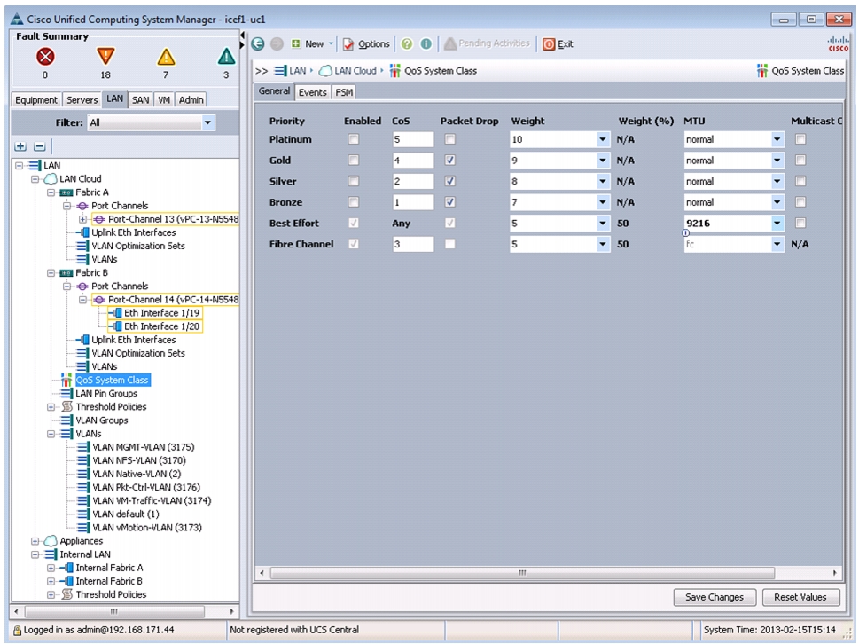
Set Jumbo Frames in Cisco UCS Fabric
Create Local Disk Configuration Policy (Optional)
Create Network Control Policy for Cisco Discovery Protocol
Create Server Pool Qualification Policy (Optional)
Create vNIC/vHBA Placement Policy for Virtual Machine Infrastructure Hosts
Update default Maintenance Policy
Create vHBA Templates for Fabric A and Fabric B
Create Service Profile Templates
Add More Servers to FlexPod Unit
FlexPod Cisco Nexus FCoE Storage vSphere on Clustered Data ONTAP
Add Individual Port Descriptions for Troubleshooting
Configure Virtual Port Channels
Configure Ports for Cisco Nexus 1110-X Virtual Appliances
Uplink into Existing Network Infrastructure
Create VSANs, Assign and Enable Virtual Fibre Channel Ports
Clustered Data ONTAP SAN Boot Storage Setup
VMware vSphere 5.1Update1 Setup
FlexPod VMware ESXi 5.1Update1 FCoE on Clustered Data ONTAP
Log in to Cisco UCS 6200 Fabric Interconnect
Set Up VMware ESXi Installation
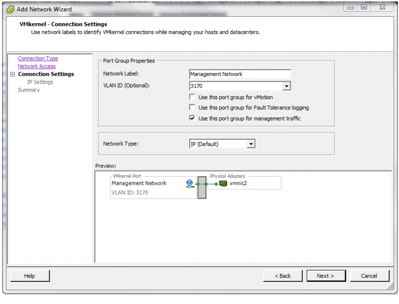
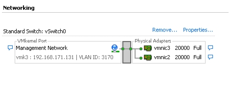
Set Up Management Networking for ESXi Hosts
Download VMware vSphere Client and vSphere Remote CLI
Log in to VMware ESXi Hosts by Using VMware vSphere Client
Download Updated Cisco VIC enic and fnic Drivers
Load Updated Cisco VIC enic and fnic Drivers
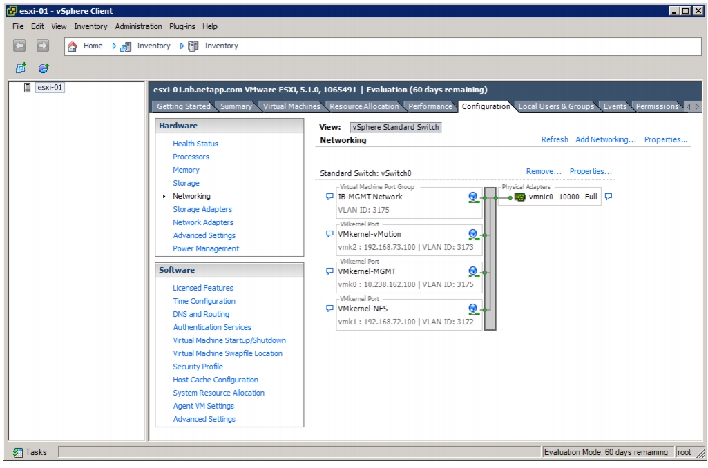
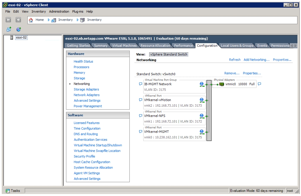
Set Up VMkernel Ports and Virtual Switch
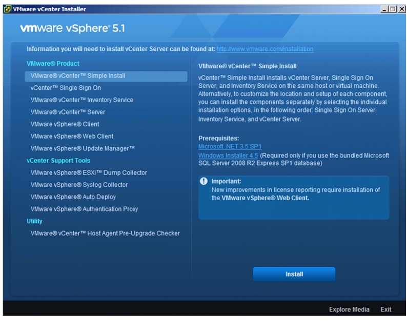
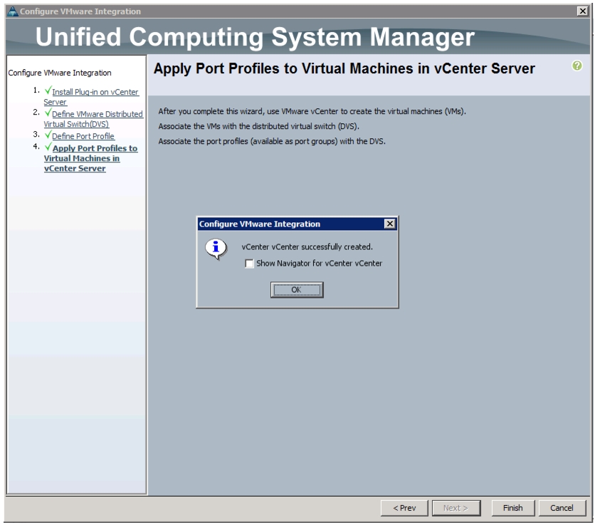
FlexPod VMware vCenter 5.1Update1
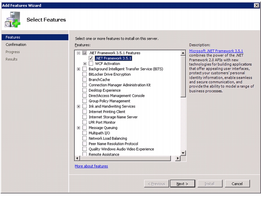
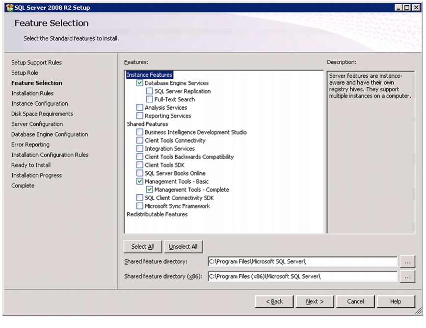
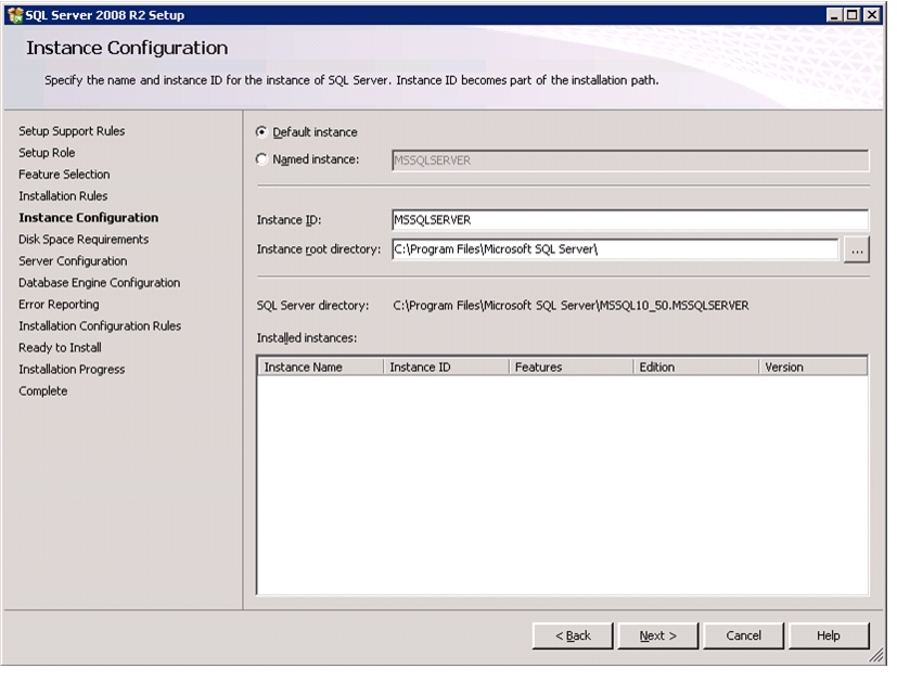
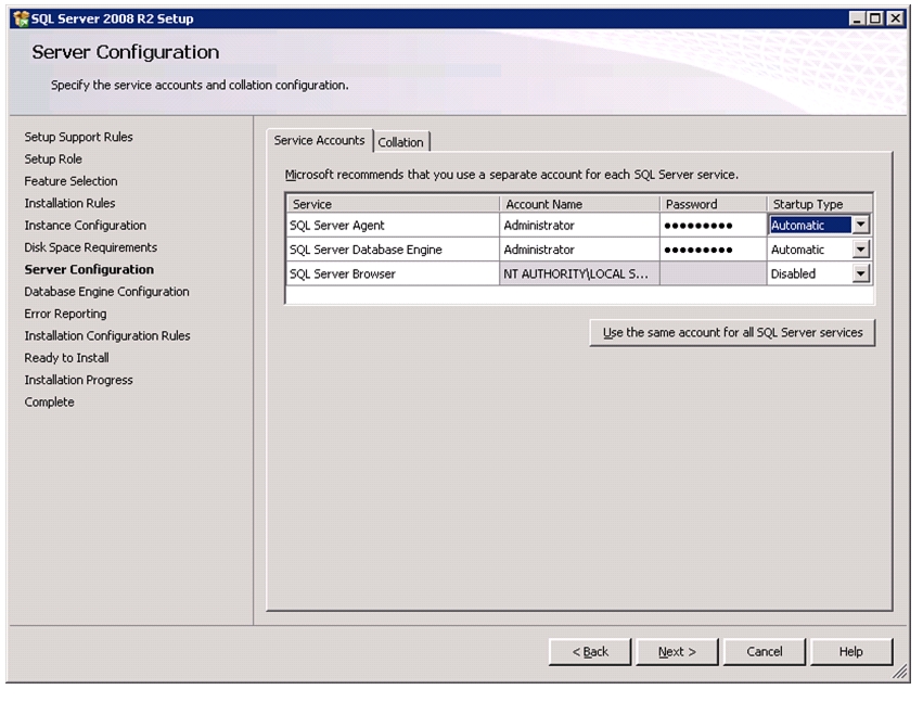
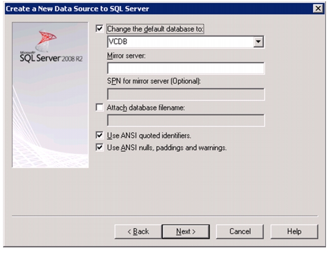
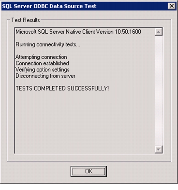
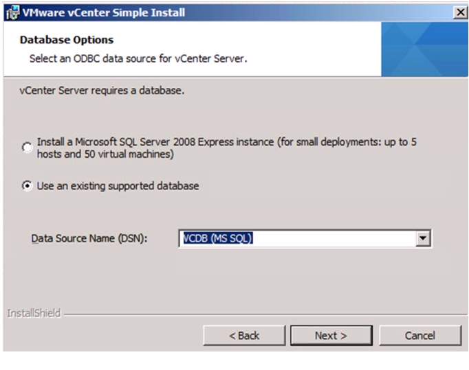
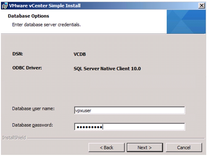
Install Microsoft SQL Server 2008 R2
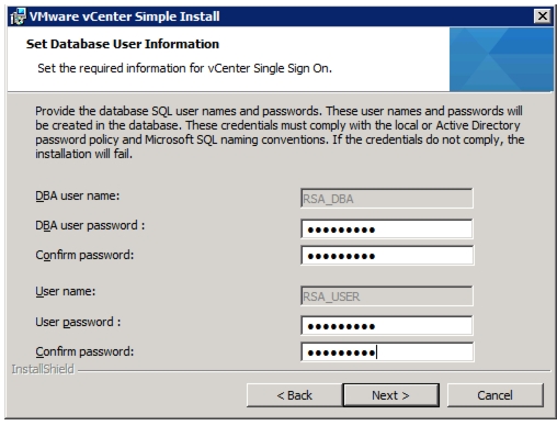
Build and Set Up VMware vCenter VM
FlexPod Cisco Nexus 1110-X and 1000V vSphere
Configure CIMC Interface on Both Cisco Nexus 1110-Xs
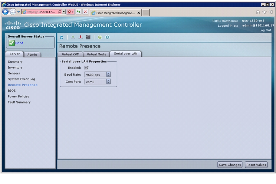
Configure Serial over LAN for Both Cisco Nexus 1110-Xs
Configure Cisco Nexus 1110-X Virtual Appliances
Set Up the Primary Cisco Nexus 1000V VSM
Set Up the Secondary Cisco Nexus 1000V VSM
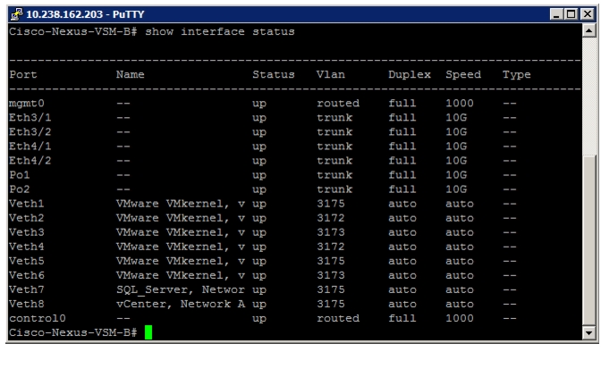
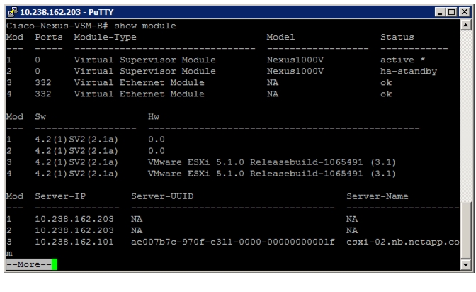
Install Virtual Ethernet Module on Each ESXi Host
Register Cisco Nexus 1000V as a vCenter Plug-in
Perform Base Configuration of the Primary VSM
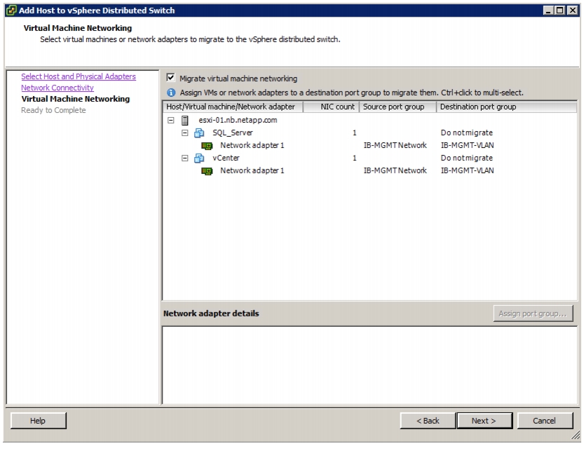
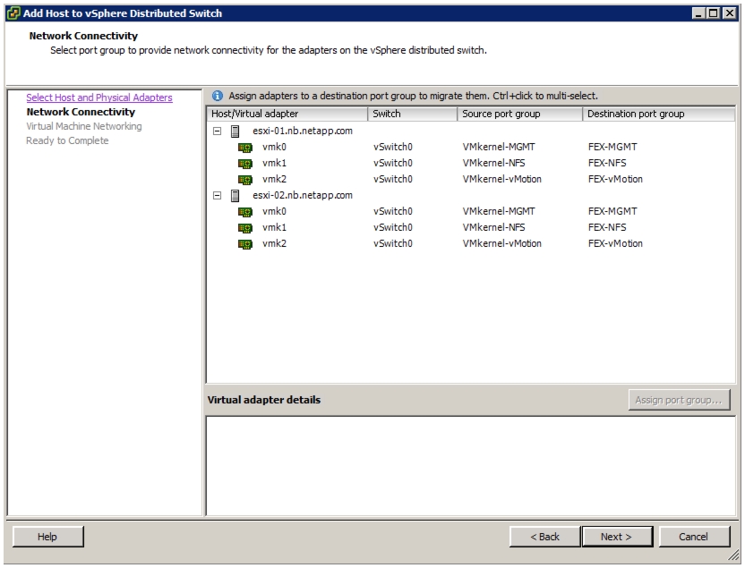
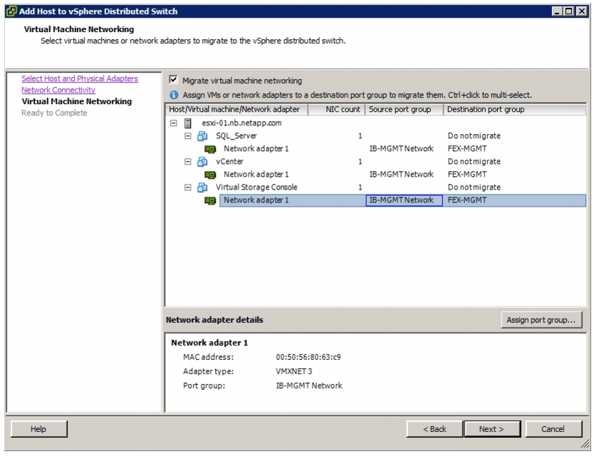
Migrate Networking Components for ESXi Hosts to Cisco Nexus 1000V
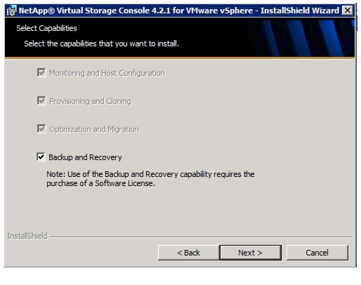
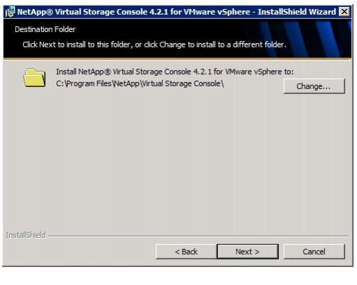
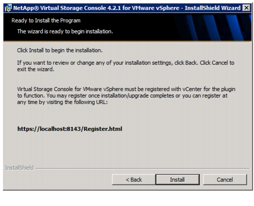
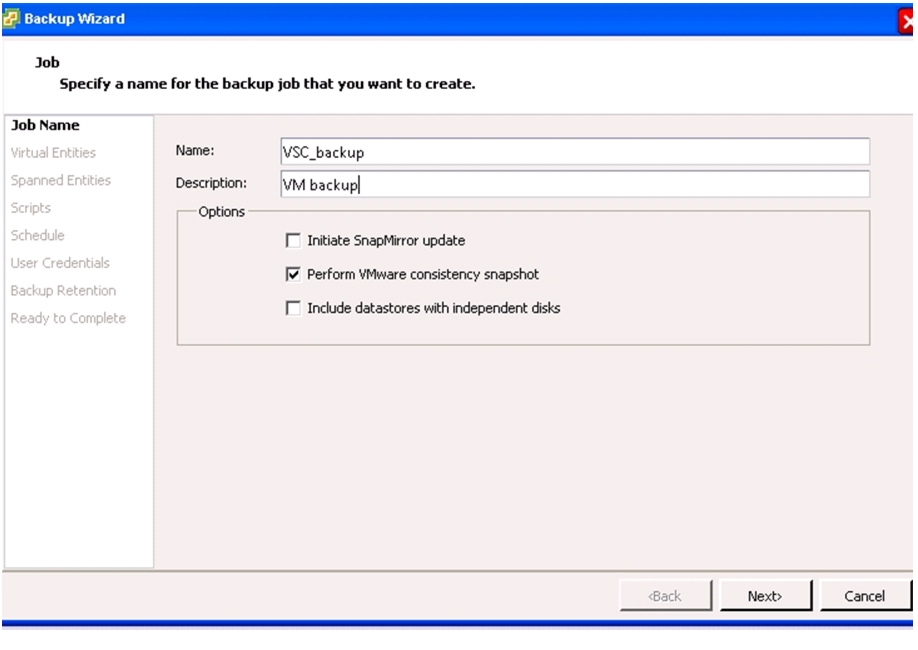
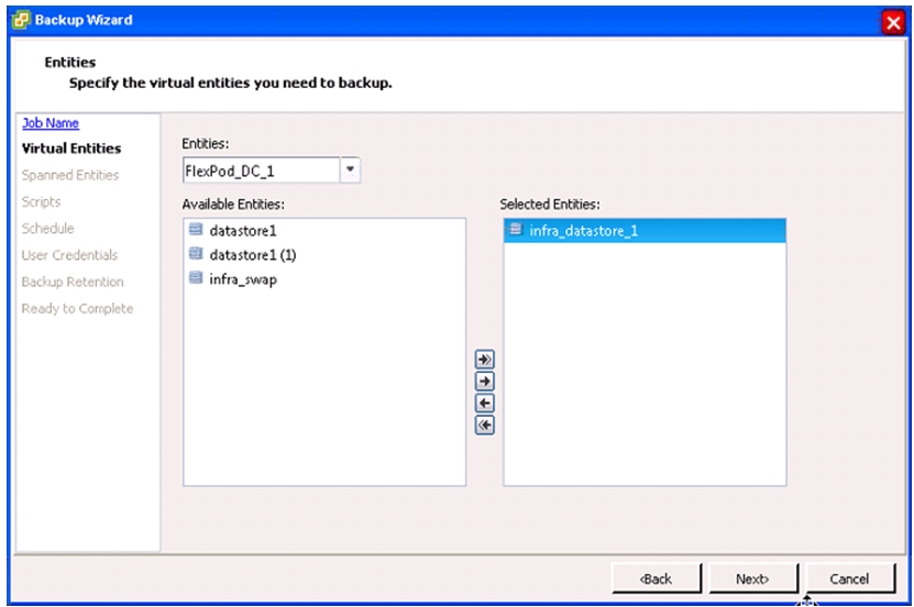
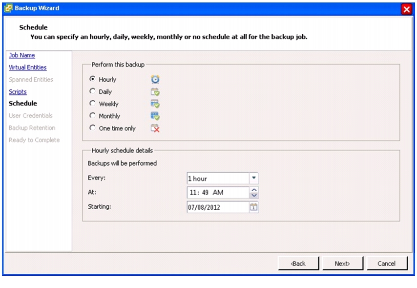
NetApp Virtual Storage Console (VSC) 4.2.1 Deployment Procedure
VSC 4.2.1 Preinstallation Considerations
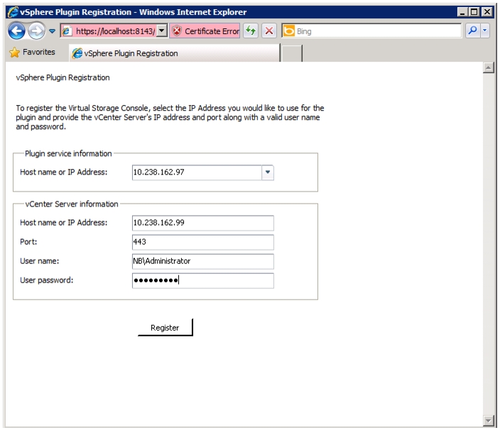
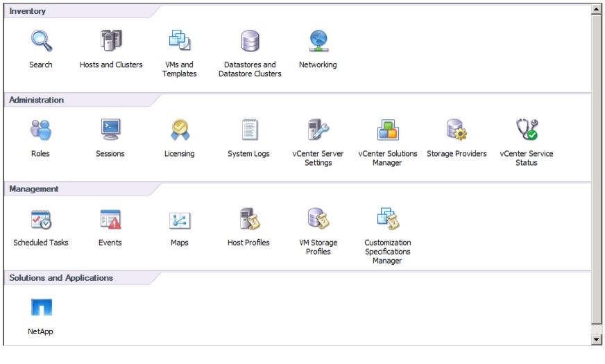
Register VSC with vCenter Server
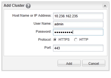
Discover and Add Storage Resources
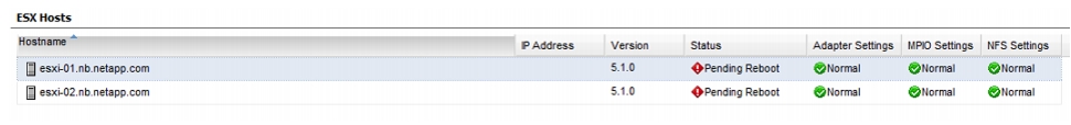
Optimal Storage Settings for ESXi Hosts
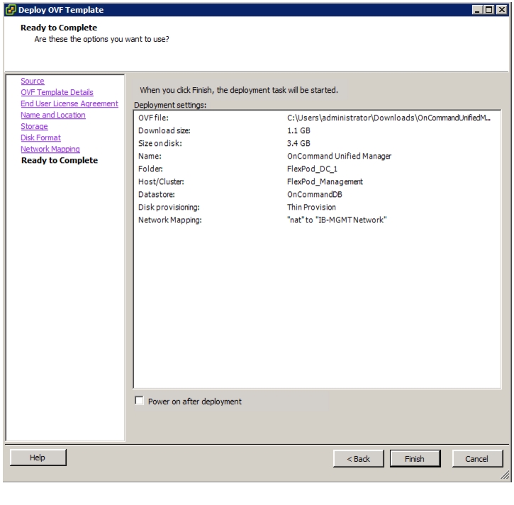
OnCommand Unified Manager OVF Deployment
OnCommand Unified Manager Basic Setup
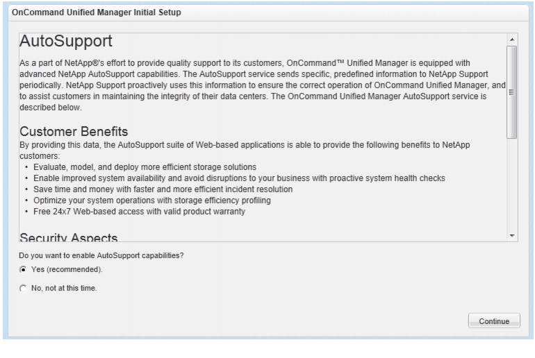
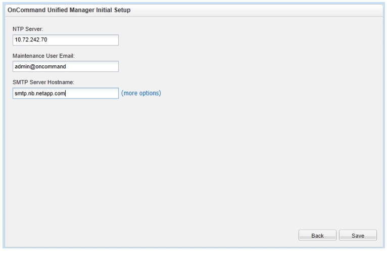
OnCommand Unified Manager Initial Setup
NetApp NFS Plug-In 1.0.20 for VMware VAAI
Install NetApp NFS Plug-In for VMware VAAI
Build Windows Active Directory Server VM(s)
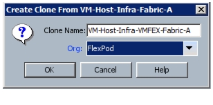
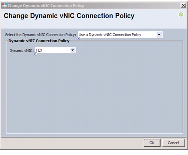
Configuring Cisco VM-FEX with the UCS Manager
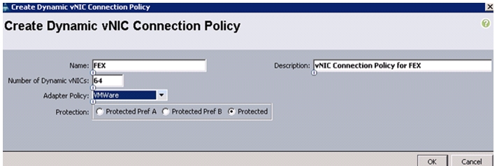
Create a Dynamic vNIC Connection Policy
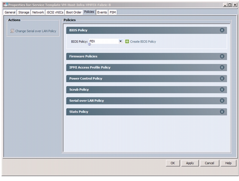
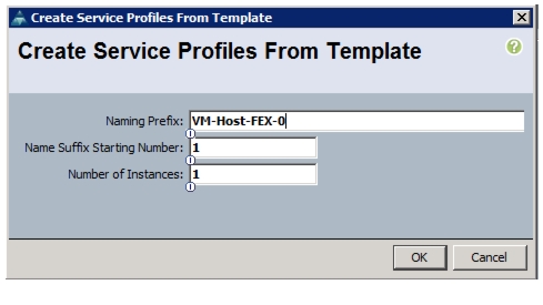
Create a VM-FEX Enabled Service Profile Template
Install and Set Up VMware ESXi
Download Cisco VEM Software Bundle
Install the FEX Virtual Ethernet Module on Each ESXi Host
Integrate Cisco UCS with vCenter
Validate Setting in VMware vCenter
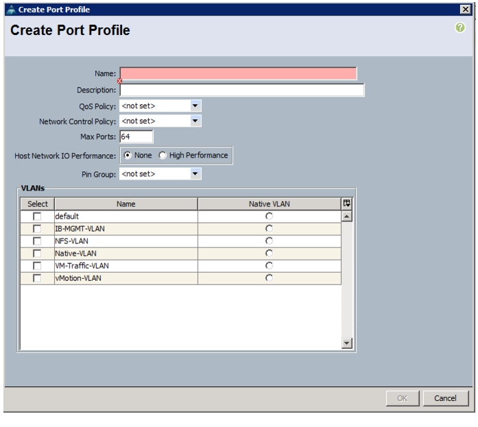
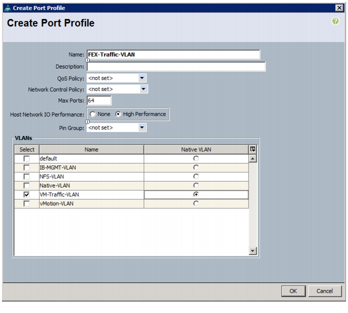
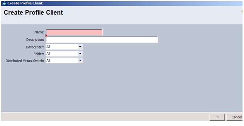
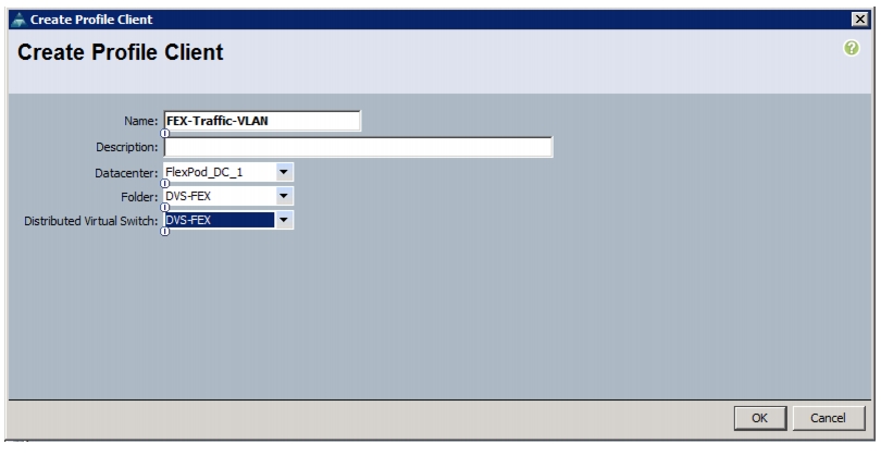
Add Distributed Port Group to the VDS (vSphere Distributed Switch)
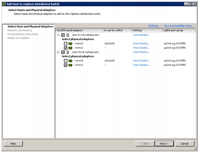
Migrate Networking Components for ESXi Hosts to Cisco DVS-FEX
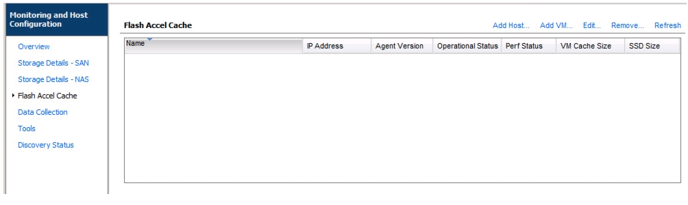
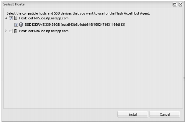
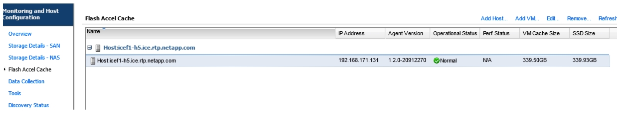
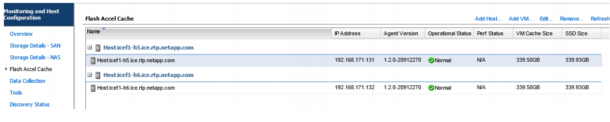
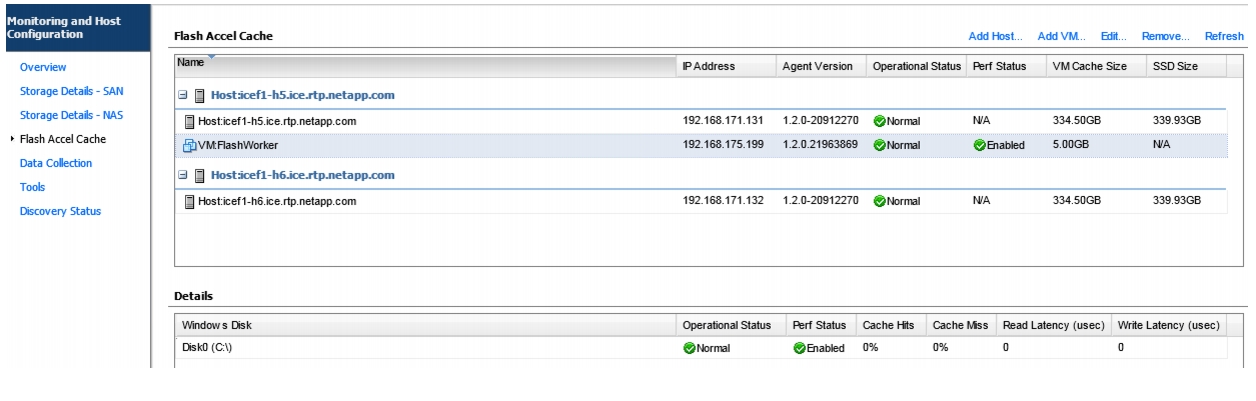
Server-Side Flash—NetApp Flash Accel with Fusion-IO
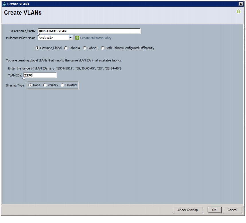
Create Out-of-Band Management VLAN on Cisco Nexus 5548UP Switches
Configure Port Channels with the Out-of Band Management VLAN on Cisco Nexus 5548UP Switches
Create Out-of-Band Management VLAN on the Cisco UCS
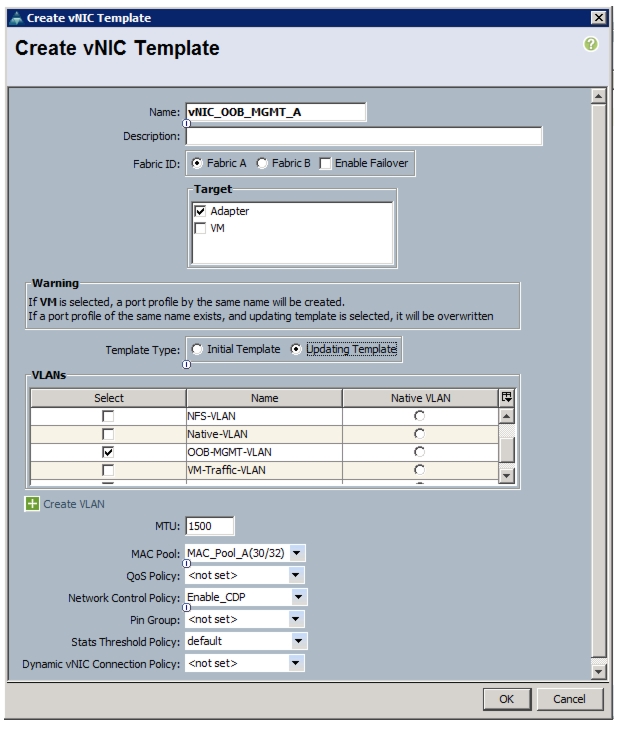
Create vNIC Templates on the Cisco UCS
Add Out-of-Band Management vNICs to ESXi Host's Service Profile
Add Management Port Group to ESXi Host
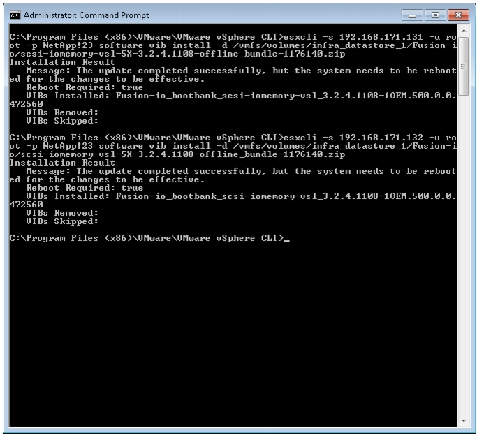
Install Fusion-io Driver on the ESXi Servers
Install Guest OS Agent and Allocate Cache
Clustered Data ONTAP— Switchless Cluster Configuration
Storage Cabling for Switchless Cluster Configuration
Switchless Cluster Configuration
Cisco UCS Central - Multi Domain Management
Obtain the UCS Central Software
Install the UCS Central Software
Add UCS Managers to UCS Central
Expand Two-Node Cluster to Four-Node Cluster FlexPod
Migrate from 7-Mode FlexPod to Clustered Data ONTAP FlexPod
Cisco Nexus 5548 Example Configurations
FlexPod Data Center with VMware vSphere 5.1Update1Deployment Guide for FlexPod with VMware vSphere 5.1Update1Last Updated: February 3, 2014
Building Architectures to Solve Business Problems
About the Authors
John Kennedy, Technical Leader, Server Access Virtualization Business Unit, Cisco SystemsJohn Kennedy is a technical marketing engineer in the Server Access and Virtualization Technology group. Currently, John is focused on the validation of FlexPod architecture while contributing to future SAVTG products. John spent two years in the Systems Development unit at Cisco, researching methods of implementing long-distance vMotion for use in the Data Center Interconnect Cisco Validated Designs. Previously, John worked at VMware for eight and a half years as a senior systems engineer supporting channel partners outside the United States and serving on the HP Alliance team. He is a VMware Certified Professional on every version of VMware ESX and ESXi, vCenter, and Virtual Infrastructure, including vSphere 5. He has presented at various industry conferences.
Chris O'Brien, Technical Marketing Manager, Server Access Virtualization Business Unit, Cisco SystemsChris O'Brien is currently focused on developing infrastructure best practices and solutions that are designed, tested, and documented to facilitate and improve customer deployments. Previously, O'Brien was an application developer and has worked in the IT industry for more than 15 years.
Arvind Ramakrishnan, Technical Marketing Engineer, Infrastructure and Cloud Engineering, NetApp SystemsArvind Ramakrishnan is a Technical Marketing Engineer in the NetApp Infrastructure and Cloud Engineering team and is focused on developing, validating, and supporting converged infrastructure solutions that include NetApp products. Before his current role, he was a software engineer at EMC developing applications for cloud infrastructure management.
Karthick Radhakrishnan, Systems Architect, Infrastructure and Cloud Engineering, NetApp SystemsKarthick Radhakrishnan is a Systems Architect in the NetApp Infrastructure and Cloud Engineering team. He focuses on validating, supporting, and implementing cloud infrastructure solutions that include NetApp products. Prior to his current role, he was a networking tools developer at America Online supporting AOL transit data network. Karthick started his career in 2003, and he holds a master's degree in Computer Application.
Lindsey Street, Systems Architect, Infrastructure and Cloud Engineering, NetApp SystemsLindsey Street is a systems architect in the NetApp Infrastructure and Cloud Engineering team. She focuses on the architecture, implementation, compatibility, and security of innovative vendor technologies to develop competitive and high-performance end-to-end cloud solutions for customers. Lindsey started her career in 2006 at Nortel as an interoperability test engineer, testing customer equipment interoperability for certification. Lindsey has her Bachelors of Science degree in Computer Networking and her Master's of Science in Information Security from East Carolina University.
John George, Reference Architect, Infrastructure and Cloud Engineering, NetApp SystemsJohn George is a Reference Architect in the NetApp Infrastructure and Cloud Engineering team and is focused on developing, validating, and supporting cloud infrastructure solutions that include NetApp products. Before his current role, he supported and administered Nortel's worldwide training network and VPN infrastructure. John holds a Master's degree in computer engineering from Clemson University.
Chris Reno, Reference Architect, Infrastructure and Cloud Engineering, NetApp SystemsChris Reno is a reference architect in the NetApp Infrastructure and Cloud Enablement group and is focused on creating, validating, supporting, and evangelizing solutions based on NetApp products. Before being employed in his current role, he worked with NetApp product engineers designing and developing innovative ways to perform Q&A for NetApp products, including enablement of a large grid infrastructure using physical and virtualized compute resources. In these roles, Chris gained expertise in stateless computing, netboot architectures, and virtualization.
About Cisco Validated Design (CVD) Program
The CVD program consists of systems and solutions designed, tested, and documented to facilitate faster, more reliable, and more predictable customer deployments. For more information visit:
http://www.cisco.com/go/designzone
ALL DESIGNS, SPECIFICATIONS, STATEMENTS, INFORMATION, AND RECOMMENDATIONS (COLLECTIVELY, "DESIGNS") IN THIS MANUAL ARE PRESENTED "AS IS," WITH ALL FAULTS. CISCO AND ITS SUPPLIERS DISCLAIM ALL WARRANTIES, INCLUDING, WITHOUT LIMITATION, THE WARRANTY OF MERCHANTABILITY, FITNESS FOR A PARTICULAR PURPOSE AND NONINFRINGEMENT OR ARISING FROM A COURSE OF DEALING, USAGE, OR TRADE PRACTICE. IN NO EVENT SHALL CISCO OR ITS SUPPLIERS BE LIABLE FOR ANY INDIRECT, SPECIAL, CONSEQUENTIAL, OR INCIDENTAL DAMAGES, INCLUDING, WITHOUT LIMITATION, LOST PROFITS OR LOSS OR DAMAGE TO DATA ARISING OUT OF THE USE OR INABILITY TO USE THE DESIGNS, EVEN IF CISCO OR ITS SUPPLIERS HAVE BEEN ADVISED OF THE POSSIBILITY OF SUCH DAMAGES.
THE DESIGNS ARE SUBJECT TO CHANGE WITHOUT NOTICE. USERS ARE SOLELY RESPONSIBLE FOR THEIR APPLICATION OF THE DESIGNS. THE DESIGNS DO NOT CONSTITUTE THE TECHNICAL OR OTHER PROFESSIONAL ADVICE OF CISCO, ITS SUPPLIERS OR PARTNERS. USERS SHOULD CONSULT THEIR OWN TECHNICAL ADVISORS BEFORE IMPLEMENTING THE DESIGNS. RESULTS MAY VARY DEPENDING ON FACTORS NOT TESTED BY CISCO.
The Cisco implementation of TCP header compression is an adaptation of a program developed by the University of California, Berkeley (UCB) as part of UCB's public domain version of the UNIX operating system. All rights reserved. Copyright © 1981, Regents of the University of California.
Cisco and the Cisco Logo are trademarks of Cisco Systems, Inc. and/or its affiliates in the U.S. and other countries. A listing of Cisco's trademarks can be found at http://www.cisco.com/go/trademarks. Third party trademarks mentioned are the property of their respective owners. The use of the word partner does not imply a partnership relationship between Cisco and any other company. (1005R)
Any Internet Protocol (IP) addresses and phone numbers used in this document are not intended to be actual addresses and phone numbers. Any examples, command display output, network topology diagrams, and other figures included in the document are shown for illustrative purposes only. Any use of actual IP addresses or phone numbers in illustrative content is unintentional and coincidental.
© 2014 Cisco Systems, Inc. All rights reserved.
FlexPod Data Center with VMware vSphere 5.1Update1
Overview
The current industry trend in data center design is towards shared infrastructures. By using virtualization along with prevalidated IT platforms, enterprise customers have embarked on the journey to the cloud by moving away from application silos and toward shared infrastructure that can be quickly deployed, thereby increasing agility and reducing costs. Cisco and NetApp have partnered to deliver FlexPod, which uses best of breed storage, server and network components to serve as the foundation for a variety of workloads, enabling efficient architectural designs that can be quickly and confidently deployed.
Audience
This document describes the architecture and deployment procedures of an infrastructure composed of Cisco®, NetApp®, and VMware® virtualization that uses FCoE-based storage serving NAS and SAN protocols. The intended audience for this document include, but is not limited to, sales engineers, field consultants, professional services, IT managers, partner engineering, and customers who want to deploy the core FlexPod architecture with NetApp clustered Data ONTAP®.
Architecture
The FlexPod architecture is highly modular or "podlike". Although each customer's FlexPod unit varies in its exact configuration, after a FlexPod unit is built, it can easily be scaled as requirements and demand change. The unit can be scaled both up (adding resources to a FlexPod unit) and out (adding more FlexPod units).
Specifically, FlexPod is a defined set of hardware and software that serves as an integrated foundation for both virtualized and nonvirtualized solutions. VMware vSphere® built on FlexPod includes NetApp storage, NetApp Data ONTAP, Cisco networking, the Cisco Unified Computing System™ (Cisco UCS®), and VMware vSphere software in a single package. The design is flexible enough that the networking, computing, and storage can fit in one data center rack or be deployed according to a customer's data center design. Port density enables the networking components to accommodate multiple configurations of this kind.
One benefit of the FlexPod architecture is the ability to customize or "flex" the environment to suit a customer's requirements. This is why the reference architecture detailed in this document highlights the resiliency, cost benefit, and ease of deployment of an FCoE-based storage solution. A storage system capable of serving multiple protocols across a single interface allows for customer choice and investment protection because it truly is a wire-once architecture.
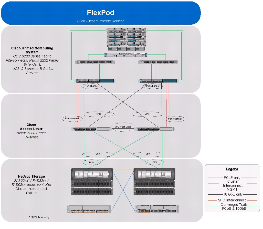
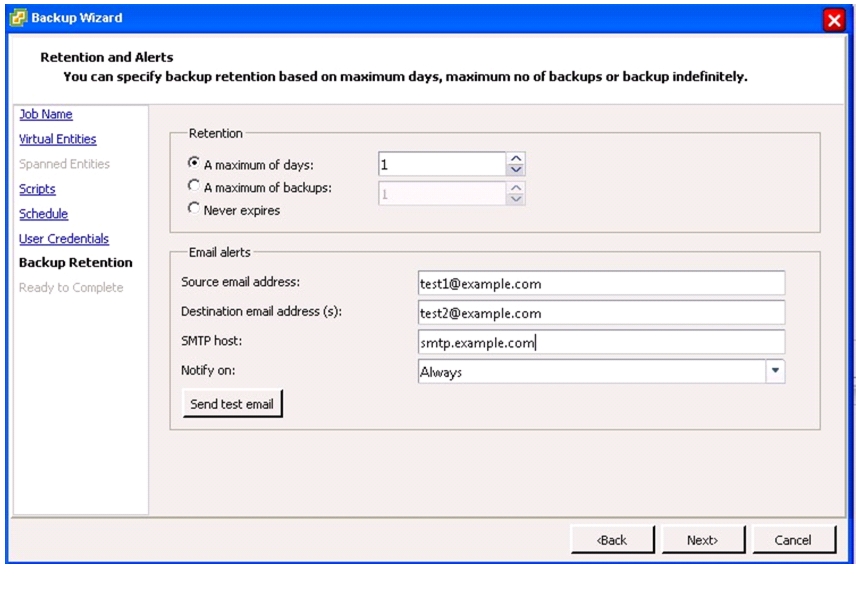
Figure 1 shows the VMware vSphere built on FlexPod components and the network connections for a configuration with FCoE-based storage. This design uses the Cisco Nexus® 5548UP, Cisco Nexus 2232PP FEX, and Cisco UCS C-Series and B-Series with the Cisco UCS virtual interface card (VIC) and the NetApp FAS family of storage controllers connected in a highly available design using Cisco Virtual PortChannels (vPCs). This infrastructure is deployed to provide FCoE-booted hosts with file- and block-level access to shared storage datastores. The reference architecture reinforces the "wire-once" strategy, because as additional storage is added to the architecture; be it FC, FCoE, or 10 Gigabit Ethernet, no recabling is required from the hosts to the Cisco UCS fabric interconnect.
Figure 1 VMware vSphere Built on Flexpod Components
The reference configuration includes:
•
Two Cisco Nexus 5548UP switches
•
•
•
•
•
•
Storage is provided by a NetApp FAS3250-AE (HA configuration in two chassis) operating in clustered Data ONTAP. All system and network links feature redundancy, providing end-to-end high availability (HA). For server virtualization, the deployment includes VMware vSphere. Although this is the base design, each of the components can be scaled flexibly to support specific business requirements. For example, more (or different) servers or even blade chassis can be deployed to increase compute capacity, additional disk shelves can be deployed to improve I/O capacity and throughput, and special hardware or software features can be added to introduce new capabilities.
This document guides you through the low-level steps for deploying the base architecture, as shown in Figure 1. These procedures cover everything from physical cabling to compute and storage configuration to configuring virtualization with VMware vSphere.
Software Revisions
It is important to note the software versions used in this document. Table 1 details the software revisions used throughout this document.
Configuration Guidelines
This document provides details for configuring a fully redundant, highly available configuration for a FlexPod unit with clustered Data ONTAP storage. Therefore, reference is made to which component is being configured with each step, either 01 or 02. For example, node01 and node02 are used to identify the two NetApp storage controllers that are provisioned with this document, and Cisco Nexus A and Cisco Nexus B identify the pair of Cisco Nexus switches that are configured. The Cisco UCS fabric interconnects are similarly configured. Additionally, this document details the steps for provisioning multiple Cisco UCS hosts, and these are identified sequentially: VM-Host-Infra-01, VM-Host-Infra-02, and so on. Finally, to indicate that you should include information pertinent to your environment in a given step, <text> appears as part of the command structure. See the following example for the network port vlan create command:
Usage:
network port vlan create ?[-node] <nodename> Node{ [-vlan-name] {<netport>|<ifgrp>} VLAN Name| -port {<netport>|<ifgrp>} Associated Network Port[-vlan-id] <integer> } Network Switch VLAN IdentifierExample:
network port vlan -node <node01> -vlan-name i0a-<vlan id>This document is intended to enable you to fully configure the customer environment. In this process, various steps require you to insert customer-specific naming conventions, IP addresses, and VLAN schemes, as well as to record appropriate MAC addresses. Table 2 describes the VLANs necessary for deployment as outlined in this guide. The VM-Mgmt VLAN is used for management interfaces of the VMware vSphere hosts. Table 3 lists the virtual storage area networks (VSANs) necessary for deployment as outlined in this guide.
Table 4 lists the configuration variables that are used throughout this document. Table 4 can be completed based on the specific site variables and used in implementing the document configuration steps.
Note
Physical Infrastructure
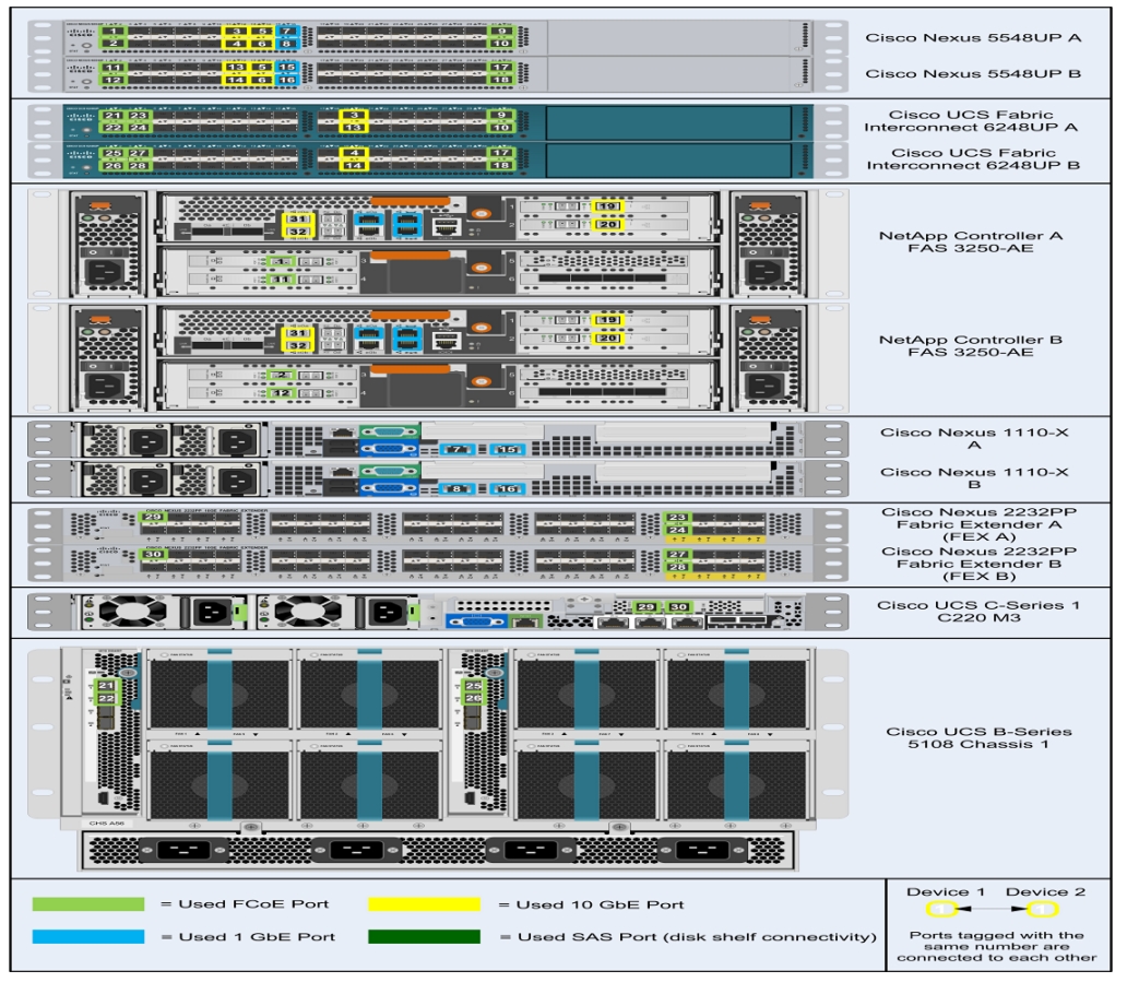
FlexPod Cabling on Clustered Data ONTAP
Figure 2 shows the cabling diagram for a FlexPod configuration using clustered Data ONTAP.
Figure 2 Flexpod Cabling Diagram in Clustered Data ONTAP
The information provided inTable 6 through Table 20 corresponds to each connection shown in Figure 2.
Note
Note
Note
Table 21 Cisco C220M3 Card Layout for Single-wire Management
1
Cisco UCS VIC 1225
CNA 2-port 10GbE (ports 0 and 1)
Storage Configuration
Controller FAS32xx Series
Table 22 Controller FAS32XX Series Prerequisites
Physical site where storage system needs to be installed must be ready
Site Reference Guide:
http://support.netapp.com/NOW/public/knowledge/docs/hardware/NetApp/site/pdf/site.pdf
Refer to the "Site Preparation" section
Storage system connectivity requirements
Site Reference Guide:
http://support.netapp.com/NOW/public/knowledge/docs/hardware/NetApp/site/pdf/site.pdf
Refer to the "System Connectivity Requirements" section
Storage system general power requirements
Site Reference Guide:
http://support.netapp.com/NOW/public/knowledge/docs/hardware/NetApp/site/pdf/site.pdf
Refer to the "Circuit Breaker, Power Outlet Balancing, System Cabinet Power Cord Plugs, and Console Pinout Requirements" section
Storage system model-specific requirements
Site Reference Guide:
http://support.netapp.com/NOW/public/knowledge/docs/hardware/NetApp/site/pdf/site.pdf
Refer to the "FAS32xx/V32xx Series Systems" section
System Configuration Guides
The NetApp Hardware Universe provides supported hardware and software components for the specific Data ONTAP version. It provides configuration information for all NetApp storage appliances currently supported by the Data ONTAP software. They also provide a table of component compatibilities.
1.
https://now.netapp.com/NOW/knowledge/docs/hardware/NetApp/syscfg/
2.
3.
Controllers
Follow the physical installation procedures for the controllers in the FAS32xx documentation in NetApp Support site at:
https://now.netapp.com/NOW/knowledge/docs/hardware/filer/210-05224+A0.pdf
Disk Shelves
To install a disk shelf for a new storage system, see:
https://now.netapp.com/NOW/knowledge/docs/hardware/filer/210-04881+A0.pdf
For information on cabling with the controller model, see SAS Disk Shelves Universal SAS and ACP Cabling Guide at:
https://now.netapp.com/NOW/knowledge/docs/hardware/filer/215-05500_A0.pdf
Cisco NX5596 Cluster Network Switch Configuration
Initial Setup of Cisco Nexus 5596 Cluster Interconnect
The first time a Cisco Nexus 5596 cluster interconnect is accessed, it runs a setup program that prompts the user to enter an IP address and other configuration information needed for the switch to communicate over the management Ethernet interface. This information is required to configure and manage the switch. If the configuration must be changed later, the setup wizard can be accessed again by running the setup command in EXEC mode.
To set up the Cisco Nexus 5596 cluster interconnect, follow these steps on both cluster interconnects.
1.
Abort Power On Auto Provisioning and continue with normal setup ?(yes/no)[n]: yesDo you want to enforce secure password standard (yes/no): yesEnter the password for the "admin": <password>Confirm the password for "admin": <password>Would you like to enter the basic configuration dialog (yes/no): yesCreate another login account (yes/no) [n]: EnterConfigure read-only SNMP community string (yes/no) [n]: EnterConfigure read-write SNMP community string (yes/no) [n]: EnterEnter the switch name: <switchname>Continue with out-of-band (mgmt0) management configuration? (yes/no) [y]: EnterMgmt0 IPv4 address: <ic_mgmt0_ip>Mgmt0 IPv4 netmask: <ic_mgmt0_netmask>Configure the default gateway? (yes/no) [y]: EnterIPv4 address of the default gateway: <ic_mgmt0_gw>Enable the telnet service? (yes/no) [n]: EnterEnable the ssh service? (yes/no) [y]: EnterType of ssh key you would like to generate (dsa/rsa): rsaNumber of key bits <768-2048> : 1024Configure the ntp server? (yes/no) [n]: yNTP server IPv4 address: <ntp_server_ip>Enter basic FC configurations (yes/no) [n]: EnterAt the end of the setup, the configuration choices are displayed. Verify the information and save the configuration at this time.
Would you like to edit the configuration? (yes/no) [n]: <n>Use this configuration and save it? (yes/no) [y]: <y>Download and Install NetApp Cluster Switch Software
When the Cisco Nexus 5596 is being used as a cluster network switch with Data ONTAP 8.1.2, it should be running NX-OS version 5.2(1)N1(1). The show version command from the switch command line interface will show the switch version currently running on the switch. If the currently running version is not 5.2(1)N1(1), go to the NetApp Support site and download and install NX-OS 5.2(1)N1(1) for the Cisco Nexus 5596 switch. Make sure both cluster interconnects are running NX-OS version 5.2(1)N1(1).
Download and Merge of NetApp Cluster Switch Reference Configuration File
Cluster network and management network switches are shipped without the configuration files installed. These files must be downloaded to the switches during deployment. Configuration files must be downloaded when the cluster network and management network switches are first installed or after the Cisco switch software is updated or reinstalled.
After the initial setup is complete, the NetApp cluster network switch reference configuration must be transferred to the switch and merged with the existing configuration. Instructions for this task and the reference configuration files for the appropriate switches are available on the NetApp Support site.
To download configuration files to a host and install them on a Cisco Nexus 5596 switch, follow these steps on both the cluster interconnects:
1.
2.
3.
copy <transfer protocol>: bootflash: vrf management4.
***** Transfer of file Completed Successfully *****Copy complete, now saving to disk (please wait)...5.
dir bootflash:6.
copy <config file name> running-config7.
a.
–
–
–
b.
–
–
–
–
–
c.
–
–
8.
copy running-config startup-configCisco Smart Call Home Setup
To configure Smart Call Home on a Cisco Nexus 5596 switch, follow these steps:
1.
NX-5596#config tNX-5596(config)#snmp-server contact <sys-contact>NX-5596(config)#callhome2.
NX-5596(config-callhome)#email-contact <email-address>NX-5596(config-callhome)#phone-contact <+1-000-000-0000>NX-5596(config-callhome)#streetaddress <a-street-address>3.
NX-5596(config-callhome)#transport email smtp-server <ip-address> port 25 use-vrf
<vrf-name>
4.
NX-5596(config-callhome)#destination-profile CiscoTAC-1 email-addr
callhome@cisco.com vrf management
5.
NX-5596(config-callhome)#periodic-inventory notificationNX-5596(config-callhome)#periodic-inventory notification interval 306.
NX-5596(config-callhome)#enableNX-5596(config-callhome)#endNX-5596#copy running-config startup-config7.
NX-5596#callhome test inventorytrying to send test callhome inventory messagesuccessfully sent test callhome inventory message8.
SNMP Monitoring Setup
Configure SNMP by using the following example as a guideline. This example configures a host receiver for SNMPv1 traps and enables all link up/down traps.
NX-5596(config)# snmp-server host <ip-address> traps { version 1 } <community>
[udp_port <number>]
NX-5596(config)# snmp-server enable traps linkClustered Data ONTAP 8.2
Note
Complete the Configuration Worksheet
Before running the setup script, complete the Configuration worksheet from the product manual.
Table 24 Controller FAS32XX Series Prerequisites
Configuration Worksheet
https://library.netapp.com/ecm/ecm_download_file/ECMP1196796
Requires access to the NetApp Support site.
Node 1
1.
Starting AUTOBOOT press Ctrl-C to abort2.
printenv3.
4.
boot_ontap5.
Note
6.
77.
y8.
e0M9.
y10.
<<var_node01_mgmt_ip>> <<var_node01_mgmt_mask>> <<var_node01_mgmt_gateway>>11.
Note
<<var_url_boot_software>>12.
Enter13.
y14.
y
Note
15.
Starting AUTOBOOT press Ctrl-C to abort...16.
printenv
Note
17.
setenv bootarg.init.boot_clustered truesetenv bootarg.bsdportname e0M18.
autoboot19.
Ctrl - C20.
421.
y22.
y
Note
Node 2
1.
Starting AUTOBOOT press Ctrl-C to abort...2.
printenv3.
4.
boot_ontap5.
Ctrl-C
Note
6.
77.
y8.
e0M9.
y10.
<<var_node02_mgmt_ip>> <<var_node02_mgmt_mask>> <<var_node02_mgmt_gateway>>11.
Note
<<var_url_boot_software>>12.
Enter13.
y14.
y
Note
15.
Starting AUTOBOOT press Ctrl-C to abort...16.
printenv
Note
17.
setenv bootarg.init.boot_clustered truesetenv bootarg.bsdportname e0M18.
autoboot19.
Ctrl - C20.
421.
y22.
y
Note
Cluster Create in Clustered Data ONTAP
See Table 26 for prerequisites to create clustered Data ONTAP.
The first node in the cluster performs the cluster create operation. All other nodes perform a cluster join operation. The first node in the cluster is considered Node01.
1.
Welcome to the cluster setup wizard.You can enter the following commands at any time:"help" or "?" - if you want to have a question clarified,"back" - if you want to change previously answered questions, and"exit" or "quit" - if you want to quit the cluster setup wizard.Any changes you made before quitting will be saved.You can return to cluster setup at any time by typing "cluster setup".To accept a default or omit a question, do not enter a value.Do you want to create a new cluster or join an existing cluster?{create, join}:
Note
2.
create3.
Do you intend for this node to be used as a single node cluster? {yes, no} [no]:
Enter
Non-HA mode, Reboot node to activate HA Do you want to reboot now to set storage failover (SFO) to HA mode? {yes, no} [yes]: Enter4.
5.
System Defaults:Private cluster network ports [e1a,e2a].Cluster port MTU values will be set to 9000.Cluster interface IP addresses will be automatically generated.The cluster will be connected using network switches.Do you want to use these defaults? {yes, no} [yes]:6.
Note
7.
Enter the cluster name: <<var_clustername>>Enter the cluster base license key: <<var_cluster_base_license_key>>Creating cluster <<var_clustername>>Enter additional license key[]:
Note
Enter the cluster administrators (username "admin") password: <<var_password>>Retype the password: <<var_password>>Enter the cluster management interface port [e0a]: e0aEnter the cluster management interface IP address: <<var_clustermgmt_ip>>Enter the cluster management interface netmask: <<var_clustermgmt_mask>>Enter the cluster management interface default gateway: <var_clustermgmt_gateway>>8.
Enter the DNS domain names:<<var_dns_domain_name>>Enter the name server IP addresses:<<var_nameserver_ip>>
Note
9.
Where is the controller located []:<<var_node_location>>Enter the node management interface port [e0M]: e0bEnter the node management interface IP address: <<var_node01_mgmt_ip>>enter the node management interface netmask:<<var_node01_mgmt_mask>>Enter the node management interface default gateway:<<var_node01_mgmt_gateway>>
Note
10.
11.
system node reboot -node <<var_node01>>Warning: Are you sure you want to reboot the node? {y|n}: y12.
Ctrl - C13.
514.
15.
ha-config show
Note
16.
halt17.
autoboot18.
19.
20.
21.
system node reboot -node <<var_node01>>Warning: Are you sure you want to reboot the node? {y|n}: y22.
Ctrl - C23.
524.
25.
disk show -a
Note
26.
Note
disk assign -n <<var_#_of_disks>>27.
halt28.
autobootCluster Join in Clustered Data ONTAP
The first node in the cluster performs the cluster create operation. All other nodes perform a cluster join operation. The first node in the cluster is considered Node01, and the node joining the cluster in this example is Node02.
1.
Welcome to the cluster setup wizard.You can enter the following commands at any time:"help" or "?" - if you want to have a question clarified,"back" - if you want to change previously answered questions, and"exit" or "quit" - if you want to quit the cluster setup wizard.Any changes you made before quitting will be saved.You can return to cluster setup at any time by typing "cluster setup".To accept a default or omit a question, do not enter a value.Do you want to create a new cluster or join an existing cluster?{create, join}:
Note
2.
join3.
Do you intend for this node to be used as a single node cluster? {yes, no} [no]:
Enter
Non-HA mode, Reboot node to activate HA Do you want to reboot now to set storage failover (SFO) to HA mode? {yes, no} [yes]: Enter4.
5.
This node's storage failover partner is already a member of a cluster.Storage failover partners must be members of the same cluster.The cluster setup wizard will default to the cluster join dialog.Existing cluster interface configuration found:Port MTU IP Netmaske1a 9000 169.254.251.110 255.255.0.0e2a 9000 169.254.56.206 255.255.0.0Do you want to use this configuration? {yes, no} [yes]: Enter
Note
6.
Enter the name of the cluster you would like to join [<<var_clustername>>]:Enter
Note
7.
Enter the node management interface port [e0M]: e0aEnter the node management interface IP address: <<var_node02_mgmt_ip>>Enter the node management interface netmask: EnterEnter the node management interface default gateway: Enter8.
9.
10.
11.
system node reboot <<var_node02>>y12.
Ctrl - C13.
514.
y15.
Note
ha-config show16.
halt17.
Autoboot18.
19.
20.
21.
system node reboot -node <<var_node02>>Warning: Are you sure you want to reboot the node? {y|n}: y22.
Ctrl - C23.
524.
25.
disk show -a26.
Note
disk assign -n <<var_#_of_disks>>27.
halt28.
autobootLog in to the Cluster
Open an SSH connection to cluster IP or host name and log in to the admin user with the password you provided earlier.
Zero All Spare Disks
Zero all spare disks in the cluster.
disk zerosparesSet Auto-Revert on Cluster Management
To set the auto-revert parameter on the cluster management interface, enter:
network interface modify -vserver <<var_clustername>> -lif cluster_mgmt -auto-revert
true
Failover Groups Management in Clustered Data ONTAP
Create a management port failover group.
network interface failover-groups create -failover-group fg-cluster-mgmt -node
<<var_node01>> -port e0a
network interface failover-groups create -failover-group fg-cluster-mgmt -node <<var_node02>> -port e0aAssign Management Failover Group to Cluster Management LIF
Assign the management port failover group to the cluster management LIF.
network interface modify -vserver <<var_clustername>> -lif cluster_mgmt
-failover-group fg-cluster-mgmt
Failover Groups Node Management in Clustered Data ONTAP
Create a management port failover group.
network interface failover-groups create -failover-group fg-node-mgmt-01 -node
<<var_node01>> -port e0a
network interface failover-groups create -failover-group fg-node-mgmt-01 -node <<var_node01>> -port e0Mnetwork interface failover-groups create -failover-group fg-node-mgmt-02 -node <<var_node02>> -port e0anetwork interface failover-groups create -failover-group fg-node-mgmt-02 -node <<var_node02>> -port e0MAssign Node Management Failover Groups to Node Management LIFs
Assign the management port failover group to the cluster management LIF.
network interface modify -vserver <<var_node01>> -lif mgmt1 -auto-revert true
-use-failover-group enabled -failover-group fg-node-mgmt-01
network interface modify -vserver <<var_node02>> -lif mgmt1 -auto-revert true -use-failover-group enabled -failover-group fg-node-mgmt-02Flash Cache in Clustered Data ONTAP
Follow these steps to enable Flash Cache on each node:
Run the following commands from the cluster management interface:
system node run -node <<var_node01>> options flexscale.enable onsystem node run -node <<var_node01>> options flexscale.lopri_blocks offsystem node run -node <<var_node01>> options flexscale.normal_data_blocks onsystem node run -node <<var_node02>> options flexscale.enable onsystem node run -node <<var_node02>> options flexscale.lopri_blocks offsystem node run -node <<var_node02>> options flexscale.normal_data_blocks on
Note
•
Aggregates in Clustered Data ONTAP
An aggregate containing the root volume is created during the Data ONTAP setup process. To create additional aggregates, determine the aggregate name, the node on which to create it, and the number of disks it will contain.
1.
aggr create -aggregate aggr01 -nodes <<var_node01>> -diskcount <<var_num_disks>>aggr create -aggregate aggr02 -nodes <<var_node02>> -diskcount <<var_num_disks>>
Note
•
•
2.
node run <<var_node01>> aggr options aggr01 nosnap onnode run <<var_node02>> aggr options aggr02 nosnap on3.
node run <<var_node01>> snap delete -A -a -f aggr01node run <<var_node02>> snap delete -A -a -f aggr024.
aggr showaggr rename -aggregate aggr0 -newname <<var_node01_rootaggrname>>Service Processor
Gather information about the network and the AutoSupport settings before configuring the Service Processor (SP).
Configure the SP using DHCP or static addressing. If the SP uses a static IP address, verify that the following SP prerequisites have been met:
•
•
•
•
A best practice is to configure the AutoSupport recipients and mail host before configuring the SP. Data ONTAP automatically sends AutoSupport configuration to the SP, allowing the SP to send alerts and notifications through an AutoSupport message to the system administrative recipients specified in AutoSupport. When configuring the SP, enter the name or the IP address of the AutoSupport mail host, when prompted.
A service processor needs to be set up on each node.
Upgrade the Service Processor on Each Node to the Latest Release
With Data ONTAP 8.2, you must upgrade to the latest service processor (SP) firmware to take advantage of the latest updates available for the remote management device.
1.
system node service-processor show2.
3.
4.
5.
6.
7.
8.
Configure the Service Processor on Node 01
1.
system node run <<var_node01>> sp setup2.
Would you like to configure the SP? YWould you like to enable DHCP on the SP LAN interface? noPlease enter the IP address of the SP[]: <<var_node01_sp_ip>>Please enter the netmask of the SP[]: <<var_node01_sp_mask>>Please enter the IP address for the SP gateway[]: <<var_node01_sp_gateway>>Configure the Service Processor on Node 02
1.
system node run <<var_node02>> sp setup2.
Would you like to configure the SP? YWould you like to enable DHCP on the SP LAN interface? noPlease enter the IP address of the SP[]: <<var_node02_sp_ip>>Please enter the netmask of the SP[]: <<var_node02_sp_mask>>Please enter the IP address for the SP gateway[]: <<var_node02_sp_gateway>>Storage Failover in Clustered Data ONTAP
Run the following commands in a failover pair to enable storage failover:
1.
storage failover show2.
3.
4.
storage failover modify -node <<var_node01>> -enabled true
Note
5.
Note
cluster ha modify -configured trueDo you want to continue? {y|n}: y6.
storage failover hwassist showstorage failover modify -hwassist-partner-ip <<var_node02_mgmt_ip>> -node <<var_node01>>storage failover modify -hwassist-partner-ip <<var_node01_mgmt_ip>> -node <<var_node02>>IFGRP LACP in Clustered Data ONTAP
This type of interface group requires two or more Ethernet interfaces and a switch that supports LACP. Therefore, make sure that the switch is configured properly.
1.
ifgrp create -node <<var_node01>> -ifgrp a0a -distr-func port -mode multimode_lacpnetwork port ifgrp add-port -node <<var_node01>> -ifgrp a0a -port e3anetwork port ifgrp add-port -node <<var_node01>> -ifgrp a0a -port e4aifgrp create -node <<var_node02>> -ifgrp a0a -distr-func port -mode multimode_lacpnetwork port ifgrp add-port -node <<var_node02>> -ifgrp a0a -port e3anetwork port ifgrp add-port -node <<var_node02>> -ifgrp a0a -port e4a
Note
•
VLAN in Clustered Data ONTAP
Create NFS VLANs.
network port vlan create -node <<var_node01>> -vlan-name a0a-<<var_nfs_vlan_id>>network port vlan create -node <<var_node02>> -vlan-name a0a-<<var_nfs_vlan_id>>Jumbo Frames in Clustered Data ONTAP
To configure a clustered Data ONTAP network port to use jumbo frames (which usually have an MTU of 9,000 bytes), run the following command from the cluster shell:
network port modify -node <<var_node01>> -port a0a-<<var_nfs_vlan_id>> -mtu 9000Warning: Changing the network port settings will cause a serveral second interruption in carrier.Do you want to continue? {y|n}: ynetwork port modify -node <<var_node02>> -port a0a-<<var_nfs_vlan_id>> -mtu 9000Warning: Changing the network port settings will cause a several second interruption in carrier.Do you want to continue? {y|n}: yNTP in Clustered Data ONTAP
To configure time synchronization on the cluster, follow these steps:
1.
timezone <<var_timezone>>
Note
2.
date <ccyymmddhhmm.ss>
Note
3.
system services ntp server create -node <<var_node01>> -server
<<var_global_ntp_server_ip>>
system services ntp server create -node <<var_node02>> -server <<var_global_ntp_server_ip>>SNMP in Clustered Data ONTAP
1.
snmp contact <<var_snmp_contact>>snmp location "<<var_snmp_location>>"snmp init 1options snmp.enable on2.
snmp traphost add <<var_oncommand_server_fqdn>>SNMPv1 in Clustered Data ONTAP
Set the shared secret plain-text password, which is called a community.
snmp community delete allsnmp community add ro <<var_snmp_community>>
Note
SNMPv3 in Clustered Data ONTAP
SNMPv3 requires that a user be defined and configured for authentication.
1.
security login create -username snmpv3user -authmethod usm -application snmp2.
3.
4.
5.
6.
AutoSupport HTTPS in Clustered Data ONTAP
AutoSupport sends support summary information to NetApp through HTTPS.
Execute the following commands to configure AutoSupport:
system node autosupport modify -node * -state enable -mail-hosts <<var_mailhost>>
-transport https -support enable -noteto <<var_storage_admin_email>>
Cisco Discovery Protocol in Clustered Data ONTAP
To enable Cisco Discovery Protocol (CDP) on the NetApp storage controllers, execute the following steps:
Note
Enable CDP on Data ONTAP:
node run -node <<var_node01>> options cdpd.enable onnode run -node <<var_node02>> options cdpd.enable onVserver (Storage Virtual Machine)
To create an infrastructure Vserver, follow these steps:
1.
vserver setupWelcome to the Vserver Setup Wizard, which will lead you throughthe steps to create a virtual storage server that serves data to clients.You can enter the following commands at any time:"help" or "?" if you want to have a question clarified,"back" if you want to change your answers to previous questions, and"exit" if you want to quit the Vserver Setup Wizard. Any changesyou made before typing "exit" will be applied.You can restart the Vserver Setup Wizard by typing "vserver setup". To accept a defaultor omit a question, do not enter a value.Step 1. Create a Vserver.You can type "back", "exit", or "help" at any question.2.
Enter the Vserver name:Infra_Vserver3.
Choose the Vserver data protocols to be configured {nfs, cifs, fcp, iscsi,
ndmp}:nfs, fcp
4.
Choose the Vserver client services to configure {ldap, nis, dns}:Enter5.
Enter the Vserver's root volume aggregate {aggr01, aggr02} [aggr01]:aggr016.
Enter the Vserver language setting, or "help" to see all languages [C]:Enter7.
Enter the Vservers root volume's security style {unix, ntfs, mixed]} [unix]: Enter8.
Do you want to create a data volume? {yes, no} [Yes]: no9.
Do you want to create a logical interface? {yes, no} [Yes]: no10.
Do you want to Configure FCP? {yes, no} [yes]: no11.
vserver modify -vserver Infra_Vserver -aggr-list aggr01, aggr02Create Load Sharing Mirror of Vserver Root Volume in Clustered Data ONTAP
1.
volume create -vserver Infra_Vserver -volume root_vol_m01 -aggregate aggr01 -size
1GB -type DP
volume create -vserver Infra_Vserver -volume root_vol_m02 -aggregate aggr02 -size 1GB -type DP2.
snapmirror create -source-path //Infra_Vserver/root_vol -destination-path
//Infra_Vserver/root_vol_m01 -type LS
snapmirror create -source-path //Infra_Vserver/root_vol -destination-path //Infra_Vserver/root_vol_m02 -type LS3.
snapmirror initialize-ls-set -source-path //Infra_Vserver/root_vol4.
job schedule interval create -name 15min -minutes 15snapmirror modify -source-path //Infra_Vserver/rootvol -destination-path * -schedule 15minFC Service in Clustered Data ONTAP
Create the FC service on each Vserver. This command also starts the FC service and sets the FC alias to the name of the Vserver.
fcp create -vserver Infra_VserverHTTPS Access in Clustered Data ONTAP
Secure access to the storage controller must be configured.
1.
set -privilege advancedDo you want to continue? {y|n}: y2.
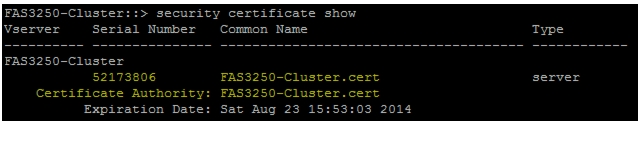
security certificate show3.
Note
security certificate create -vserver Infra_Vserver -common-name
<<var_security_cert_vserver_common_name>> -size 2048 -country <<var_country_code>>
-state <<var_state>> -locality <<var_city>> -organization <<var_org>> -unit
<<var_unit>> -email <<var_storage_admin_email>>
security certificate create -vserver <<var_clustername>> -common-name <<var_security_cert_cluster_common_name>> -size 2048 -country <<var_country_code>> -state <<var_state>> -locality <<var_city>> -organization <<var_org>> -unit <<var_unit>> -email <<var_storage_admin_email>>security certificate create -vserver <<var_node01>> -common-name <<var_security_cert_node01_common_name>> -size 2048 -country <<var_country_code>> -state <<var_state>> -locality <<var_city>> -organization <<var_org>> -unit <<var_unit>> -email <<var_storage_admin_email>>security certificate create -vserver <<var_node02>> -common-name <<var_security_cert_node02_common_name>> -size 2048 -country <<var_country_code>> -state <<var_state>> -locality <<var_city>> -organization <<var_org>> -unit <<var_unit>> -email <<var_storage_admin_email>>4.
system services web modify -external true -sslv3-enabled trueDo you want to continue {y|n}: ysystem services firewall policy delete -policy mgmt -service http -action allowsystem services firewall policy create -policy mgmt -service http -action deny -ip-list 0.0.0.0/0system services firewall policy delete -policy mgmt -service telnet -action allowsystem services firewall policy create -policy mgmt -service telnet -action deny -ip-list 0.0.0.0/05.
6.
7.
–
–
–
8.
security ssl modify -vserver Infra_Vserver -common-name
<<var_security_cert_vserver_common_name>>
-server-enabled true -client-enabled false -ca <<var_security_certificate_vservser_authority>> -serial <<var_security_certificate_vserver_serial_no>>security ssl modify -vserver <<var_clustername>> -common-name <<var_security_cert_cluster_common_name>>-server-enabled true -client-enabled false -ca <<var_security_certificate_cluster_authority>> -serial <<var_security_certificate_cluster_serial_no>>security ssl modify -vserver <<var_node01>> -common-name <<var_security_cert_node01_common_name>>-server-enabled true -client-enabled false -ca <<var_security_certificate_node01_authority>> -serial <<var_security_certificate_node01_serial_no>>security ssl modify -vserver <<var_node02>>-common-name <<var_security_cert_node02_common_name>>-server-enabled true -client-enabled false -ca <<var_security_certificate_node02_authority>> -serial <<var_security_certificate_node02_serial_no>>set -privilege adminvserver services web modify -name spi|ontapi|compat -vserver * -enabled truevserver services web access create -name spi -role admin -vserver <<var_clustername>>vserver services web access create -name ontapi -role admin -vserver <<var_clustername>>
Note
NFSv3 in Clustered Data ONTAP
Run all commands to configure NFS on the Vserver.
1.
vserver export-policy rule modify -vserver Infra_Vserver -policyname default
-ruleindex 1 -rorule never -rwrule never -superuser none
vserver export-policy create -vserver Infra_Vserver FlexPod2.
Note
vserver export-policy rule create -vserver Infra_Vserver -policyname FlexPod
-ruleindex 1 -protocol nfs -clientmatch <<var_esxi_host1_nfs_ip>> -rorule sys
-rwrule sys -superuser sys -allow-suid false
3.
volume modify -vserver Infra_Vserver -volume root_vol -policy FlexPodFlexVol in Clustered Data ONTAP
The following information is required to create a FlexVol® volume: the volume's name and size, and the aggregate on which it will exist. Create two VMware datastore volumes, a server boot volume, and a volume to hold the OnCommand database LUN. Also, update the Vserver root volume load sharing mirrors to make the NFS mounts accessible.
volume create -vserver Infra_Vserver -volume infra_datastore_1 -aggregate aggr02
-size 500g -state online -policy FlexPod -junction-path /infra_datastore_1
-space-guarantee none -percent-snapshot-space 0
volume create -vserver Infra_Vserver -volume infra_swap -aggregate aggr01 -size 100g -state online -policy FlexPod -junction-path /infra_swap -space-guarantee none -percent-snapshot-space 0 -snapshot-policy nonevolume create -vserver Infra_Vserver -volume esxi_boot -aggregate aggr01 -size 100g -state online -policy default -space-guarantee none -percent-snapshot-space 0volume create -vserver Infra_Vserver -volume OnCommandDB -aggregate aggr02 -size 200g -state online -policy Flexpod -junction-path /OnCommandDB -space-guarantee none -percent-snapshot-space 0snapmirror update-ls-set -source-path //Infra_Vserver/rootvolLUN in Clustered Data ONTAP
1.
lun create -vserver Infra_Vserver -volume esxi_boot -lun VM-Host-Infra-01 -size
10g -ostype vmware -space-reserve disabled
lun create -vserver Infra_Vserver -volume esxi_boot -lun VM-Host-Infra-02 -size 10g -ostype vmware -space-reserve disabledDeduplication in Clustered Data ONTAP
Enable deduplication on appropriate volumes.
volume efficiency on -vserver Infra_Vserver -volume infra_datastore_1volume efficiency on -vserver Infra_Vserver -volume esxi_bootvolume efficiency on -vserver Infra_Vserver -volume OnCommandDBFailover Groups NAS in Clustered Data ONTAP
Create an NFS port failover group.
network interface failover-groups create -failover-group
fg-nfs-<<var_nfs_vlan_id>> -node <<var_node01>> -port a0a-<<var_nfs_vlan_id>>
network interface failover-groups create -failover-group fg-nfs-<<var_nfs_vlan_id>> -node <<var_node02>> -port a0a-<<var_nfs_vlan_id>>NFS LIF in Clustered Data ONTAP
Create an NFS logical interface (LIF).
network interface create -vserver Infra_Vserver -lif nfs_lif01 -role data
-data-protocol nfs -home-node <<var_node01>> -home-port a0a-<<var_nfs_vlan_id>>
-address <<var_node01_nfs_lif_ip>> -netmask <<var_node01_nfs_lif_mask>>
-status-admin up -failover-policy nextavail -firewall-policy data -auto-revert
true -use-failover-group enabled -failover-group fg-nfs-<<var_nfs_vlan_id>>
network interface create -vserver Infra_Vserver -lif nfs_lif02 -role data -data-protocol nfs -home-node <<var_node02>> -home-port a0a-<<var_nfs_vlan_id>> -address <<var_node02_nfs_lif_ip>> -netmask <<var_node02_nfs_lif_mask>> -status-admin up -failover-policy nextavail -firewall-policy data -auto-revert true -use-failover-group enabled -failover-group fg-nfs-<<var_nfs_vlan_id>>FCP LIF in Clustered Data ONTAP
Create four FCoE LIFs, two on each node.
network interface create -vserver Infra_Vserver -lif fcp_lif01a -role data
-data-protocol fcp -home-node <<var_node01>> -home-port 3a
network interface create -vserver Infra_Vserver -lif fcp_lif01b -role data -data-protocol fcp -home-node <<var_node01>> -home-port 4anetwork interface create -vserver Infra_Vserver -lif fcp_lif02a -role data -data-protocol fcp -home-node <<var_node02>> -home-port 3anetwork interface create -vserver Infra_Vserver -lif fcp_lif02b -role data -data-protocol fcp -home-node <<var_node02>> -home-port 4aAdd Infrastructure Vserver Administrator
Add the infrastructure Vserver administrator and Vserver administration logical interface in the out-of-band management network with the following commands:
network interface create -vserver Infra_Vserver -lif vsmgmt -role data
-data-protocol none -home-node <<var_node02>> -home-port e0a -address
<<var_vserver_mgmt_ip>> -netmask <<var_vserver_mgmt_mask>> -status-admin up
-failover-policy nextavail -firewall-policy mgmt -auto-revert true -failover-group
mgmt
network routing-groups route create -vserver Infra_Vserver -routing-group d<<var_clustermgmt_ip>> -destination 0.0.0.0/0 -gateway <<var_clustermgmt_gateway>>security login password -username vsadmin -vserver Infra_VserverEnter a new password: <<var_vsadmin_password>>Enter it again: <<var_vsadmin_password>>security login unlock -username vsadmin -vserver Infra_VserverServer Configuration
FlexPod Cisco UCS Base
Perform Initial Setup of Cisco UCS 6248 Fabric Interconnect for FlexPod Environments
This section provides detailed procedures for configuring the Cisco Unified Computing System (Cisco UCS) for use in a FlexPod environment. These steps are necessary to provision the Cisco UCS C-Series and B-Series servers and should be followed precisely to avoid improper configuration.
Cisco UCS 6248UP Fabric Interconnect A
To configure the Cisco UCS for use in a FlexPod environment, follow these steps:
1.
Enter the configuration method. (console/gui) ? consoleEnter the setup mode; setup newly or restore from backup.(setup/restore)? setupYou have chosen to setup a new Fabric interconnect. Continue? (y/n): yEnforce strong password? (y/n) [y]: yEnter the password for "admin": <<var_password>>Confirm the password for "admin": <<var_password>>Is this fabric interconnect part of a cluster (select 'no' for standalone)? (yes/no) [n]: yEnter the switch fabric (A/B) []:AEnter the system name: <<var_ucs_clustername>>Physical switch Mgmt0 IPv4 address: <<var_ucsa_mgmt_ip>>Physical switch Mgmt0 IPv4 netmask: <<var_ucsa_mgmt_mask>>IPv4 address of the default gateway: <<var_ucsa_mgmt_gateway>>Cluster IPv4 address: <<var_ucs_cluster_ip>>Configure the DNS Server IPv4 address? (yes/no) [n]: yDNS IPv4 address: <<var_nameserver_ip>>Configure the default domain name? (yes/no) [n]: yDefault domain name: <<var_dns_domain_name>>Join centralized management environment (UCS Central)? (yes/no) [n]: Enter2.
3.
Cisco UCS 6248UP Fabric Interconnect B
To configure the Cisco UCS for use in a FlexPod environment, follow these steps:
1.
Enter the configuration method. (console/gui) ? consoleInstaller has detected the presence of a peer Fabric interconnect. This Fabric interconnect will be added to the cluster. Continue (y/n) ? yEnter the admin password of the peer Fabric interconnect: <<var_password>>Physical switch Mgmt0 IPv4 address: <<var_ucsb_mgmt_ip>>Apply and save the configuration (select `no' if you want to re-enter)? (yes/no): y2.
FlexPod Cisco UCS FCoE vSphere on Clustered Data ONTAP
Log in to Cisco UCS Manager
To log in to the Cisco Unified Computing System (UCS) environment, follow these steps:
1.
2.
3.
4.
5.
Upgrade Cisco UCS Manager Software to Version 2.1(1b)
This document assumes the use of Cisco UCS 2.1(3a). To upgrade the Cisco UCS Manager software and the UCS 6248 Fabric Interconnect software to version 2.1(3a), see Cisco UCS Manager Install and Upgrade Guides.
Add Block of IP Addresses for KVM Access
To create a block of IP addresses for server Keyboard, Video, Mouse (KVM) access in the Cisco UCS environment, follow these steps:
Note
1.
2.
3.
4.
5.
6.
Synchronize Cisco UCS to NTP
To synchronize the Cisco UCS environment to the NTP server, follow these steps:
1.
2.
3.
4.
5.
6.
7.
Edit Chassis Discovery Policy
Setting the discovery policy simplifies the addition of B-Series Cisco UCS chassis and of additional fabric extenders for further C-Series connectivity.
To modify the chassis discovery policy, follow these steps:
1.
2.
3.
4.
5.
6.
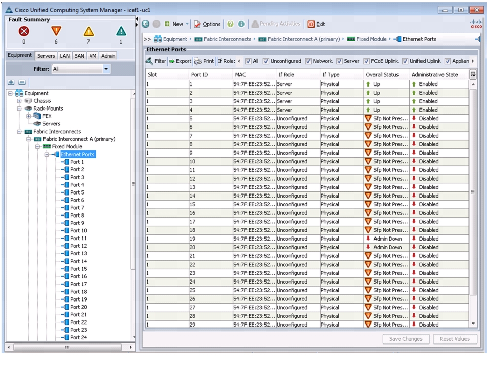
Enable Server and Uplink Ports
To enable server and uplink ports, follow these steps:
1.
2.
3.
4.
5.
6.
Figure 3 Configured Server Ports
7.
8.
9.
10.
11.
12.
13.
14.
15.
16.
17.
18.
Acknowledge Cisco UCS Chassis and FEX
To acknowledge all Cisco UCS chassis and external 2232 FEX modules, follow these steps:
1.
2.
3.
Figure 4 Acknowledging Cisco UCS Chassis
4.
5.
6.
Figure 5 Acknowledging Cisco UCS Fabric Extenders
7.
Create Uplink Port Channels to Cisco Nexus 5548 Switches
To configure the necessary port channels out of the Cisco UCS environment, follow these steps:
1.
Note
2.
3.
4.
5.
6.
7.
Figure 6 Creating Port Channels
8.
–
–
9.
10.
11.
12.
13.
14.
15.
16.
17.
18.
–
–
19.
20.
21.
Create an Organization
Organizations are used to organize resources and restrict access to various groups within the IT organization, thereby enabling multi-tenancy of the compute resources.
Note
To configure an organization in the Cisco UCS environment, follow these steps:
1.
2.
3.
4.
5.
Create MAC Address Pools
To configure the necessary MAC address pools for the Cisco UCS environment, follow these steps:
1.
2.
Note
3.
4.
5.
6.
7.
8.
9.
Note
10.
Figure 7 Creating MAC Address Pool for Fabric A
11.
12.
13.
14.
15.
16.
17.
18.
19.
20.
Note
21.
Figure 8 Creating MAC Address Pool for Fabric B
22.
23.
24.
Create WWNN Pools
To configure the necessary World Wide Node Name (WWNN) pools for the Cisco UCS environment, follow these steps:
1.
2.
3.
4.
5.
6.
7.
8.
9.
10.
Figure 9 Creating WWNN Pool
11.
12.
13.
Create WWPN Pools
To configure the necessary World Wide Port Name (WWPN) pools for the Cisco UCS environment, follow these steps:
1.
2.
Note
3.
4.
5.
6.
7.
8.
9.
Note
10.
Figure 10 Creating WWPN Pool
11.
12.
13.
14.
15.
16.
17.
18.
19.
20.
Note
21.
22.
23.
24.
Create UUID Suffix Pool
To configure the necessary universally unique identifier (UUID) suffix pool for the Cisco UCS environment, follow these steps:
1.
2.
3.
4.
5.
6.
7.
8.
9.
10.
11.
Figure 11 Creating UUID Suffix Pool
12.
13.
14.
Create Server Pool
To configure the necessary server pool for the Cisco UCS environment, follow these steps:
Note
1.
2.
3.
4.
5.
6.
7.
8.
9.
10.
Create VLANs
To configure the necessary virtual local area networks (VLANs) for the Cisco UCS environment, follow these steps:
1.
Note
2.
3.
4.
5.
6.
7.
8.
9.
Figure 12 Creating VLAN for Management Traffic
10.
11.
12.
13.
14.
15.
16.
Figure 13 Creating VLAN for NFS Traffic
17.
18.
19.
20.
21.
22.
23.
Figure 14 Creating VLAN for vMotion
24.
25.
26.
27.
28.
29.
30.
Figure 15 Creating VLAN for VM Traffic
31.
32.
33.
34.
35.
36.
37.
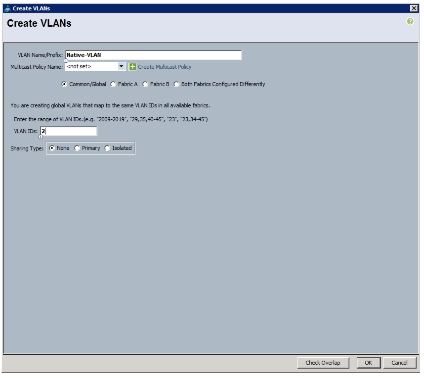
Figure 16 Creating Native VLAN
38.
39.
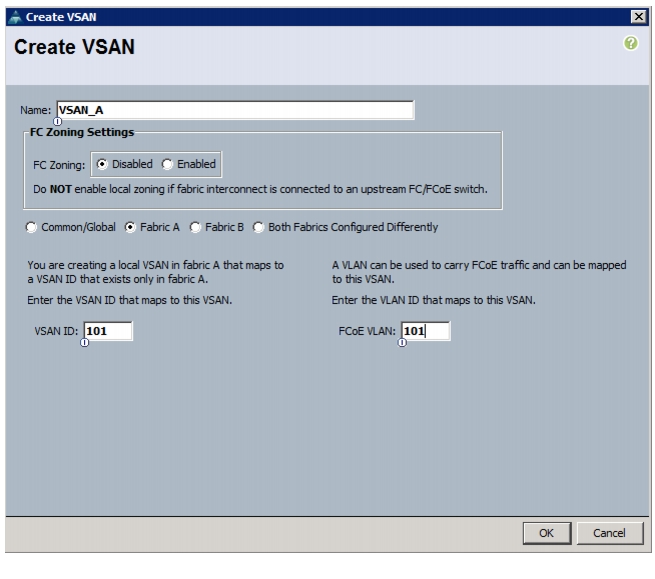
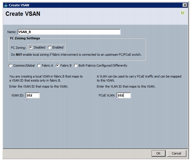
Create VSANs and FCoE Port Channels
To configure the necessary virtual storage area networks (VSANs) and FCoE uplink port channels for the Cisco UCS environment, follow these steps:
1.
2.
3.
4.
5.
6.
7.
8.
9.
Note
10.
Figure 17 Creating VSAN for Fabric A
11.
12.
13.
14.
15.
16.
17.
Note
18.
Figure 18 Creating VSAN for Fabric B
19.
20.
21.
22.
23.
24.
25.
26.
27.
28.
29.
30.
31.
32.
33.
34.
35.
36.
37.
38.
39.
40.
41.
42.
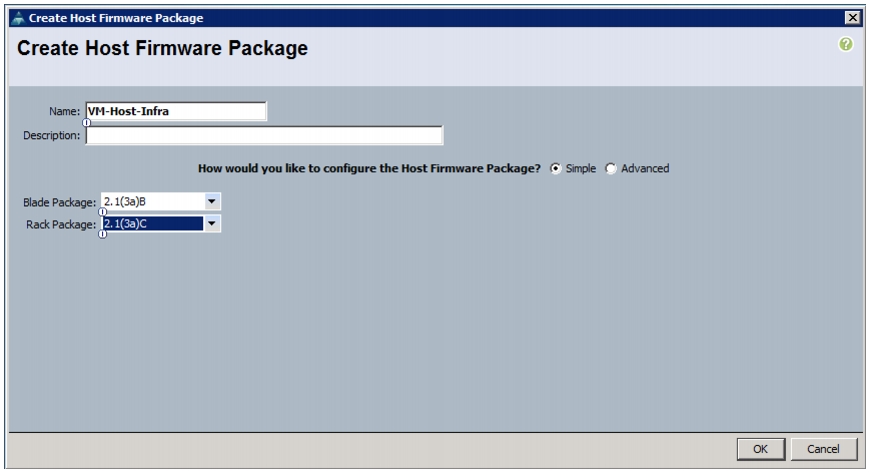
Create Host Firmware Package
Firmware management policies allow the administrator to select the corresponding packages for a given server configuration. These policies often include packages for adapter, BIOS, board controller, FC adapters, host bus adapter (HBA) option ROM, and storage controller properties.
To create a firmware management policy for a given server configuration in the Cisco UCS environment, follow these steps:
1.
2.
3.
4.
5.
6.
7.
8.
9.
Figure 19 Creating Host Firmware Package
Set Jumbo Frames in Cisco UCS Fabric
To configure jumbo frames and enable quality of service in the Cisco UCS fabric, follow these steps:
1.
2.
3.
4.
5.
6.
Figure 20 Setting Jumbo Frame
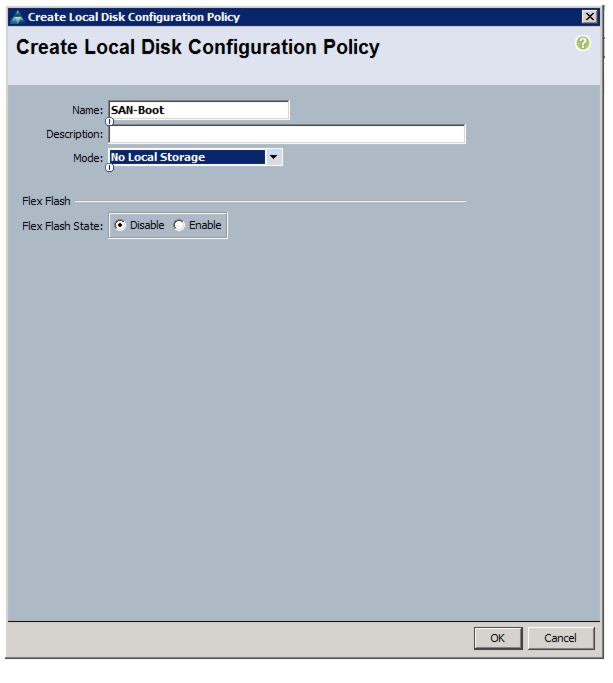
Create Local Disk Configuration Policy (Optional)
A local disk configuration for the Cisco UCS environment is necessary if the servers in the environment do not have a local disk.
Note
To create a local disk configuration policy, follow these steps:
1.
2.
3.
4.
5.
6.
7.
Figure 21 Creating Local Disk Configuration Policy
8.
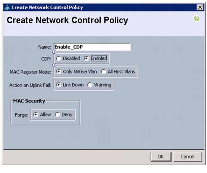
Create Network Control Policy for Cisco Discovery Protocol
To create a network control policy that enables Cisco Discovery Protocol (CDP) on virtual network ports, follow these steps:
1.
2.
3.
4.
5.
6.
7.
Figure 22 Creating Network Control Policy
8.
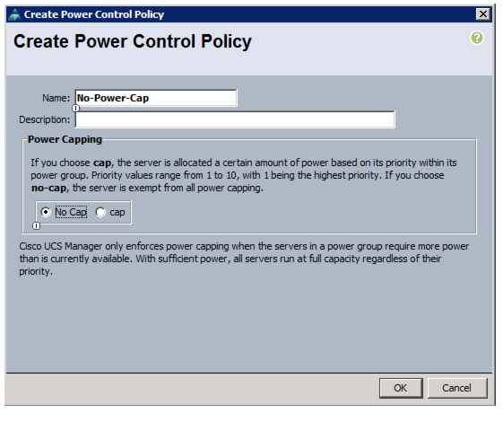
Create Power Control Policy
To create a power control policy for the Cisco UCS environment, follow these steps:
1.
2.
3.
4.
5.
6.
7.
8.
Figure 23 Creating Power Control Policy
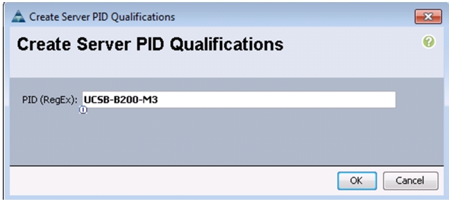
Create Server Pool Qualification Policy (Optional)
To create an optional server pool qualification policy for the Cisco UCS environment, follow these steps:
Note
1.
2.
3.
4.
5.
6.
7.
8.
9.
Figure 24 Creating Server PID Qualifications
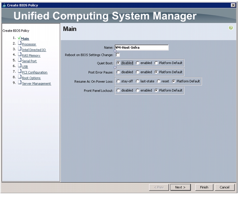
Create Server BIOS Policy
To create a server BIOS policy for the Cisco UCS environment, follow these steps:
1.
2.
3.
4.
5.
6.
7.
Figure 25 Creating BIOS Policy
8.
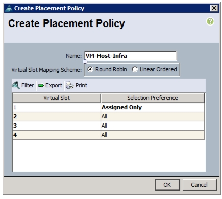
Create vNIC/vHBA Placement Policy for Virtual Machine Infrastructure Hosts
To create a vNIC/vHBA placement policy for the infrastructure hosts, follow these steps:
1.
2.
3.
4.
5.
6.
7.
Figure 26 Creating Placement Policy
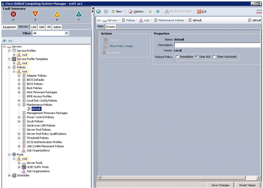
Update default Maintenance Policy
To update the default Maintenance Policy, follow these steps:
1.
2.
3.
4.
5.
6.
Figure 27 Updating Maintenance Policy
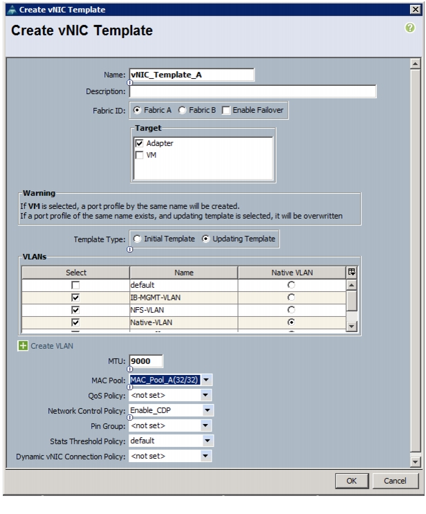
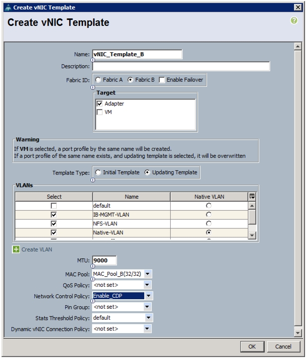
Create vNIC Templates
To create multiple virtual network interface card (vNIC) templates for the Cisco UCS environment, follow these steps:
1.
2.
3.
4.
5.
6.
7.
8.
9.
10.
11.
12.
13.
14.
15.
16.
Figure 28 Creating vNIC Template for Fabric A
17.
18.
19.
20.
21.
22.
23.
24.
25.
26.
27.
28.
29.
30.
31.
32.
Figure 29 Creating vNIC Template for Fabric B
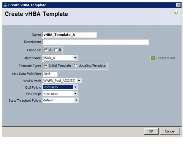
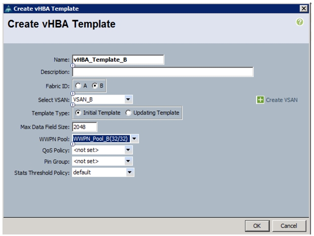
Create vHBA Templates for Fabric A and Fabric B
To create multiple virtual host bus adapter (vHBA) templates for the Cisco UCS environment, follow these steps:
1.
2.
3.
4.
5.
6.
7.
8.
9.
10.
Figure 30 Creating vHBA Template for Fabric A
11.
12.
13.
14.
15.
16.
17.
18.
19.
20.
Figure 31 Creating vHBA Template for Fabric B
Create Boot Policies
This procedure applies to a Cisco UCS environment in which two FCoE logical interfaces (LIFs) are on cluster node 1 (fcp_lif01a and fcp_lif01b) and two FCoE LIFs are on cluster node 2 (fcp_lif02a and fcp_lif02b). Also, it is assumed that the A LIFs are connected to fabric A (Cisco Nexus 5548 A) and the B LIFs are connected to fabric B (Cisco Nexus 5548 B).
Two boot policies are configured in this procedure. The first policy configures the primary target to be fcp_lif01a and the second boot policy configures the primary target to be fcp_lif01b.
To create boot policies for the Cisco UCS environment, follow these steps:
1.
2.
3.
4.
5.
6.
7.
8.
9.
10.
11.
12.
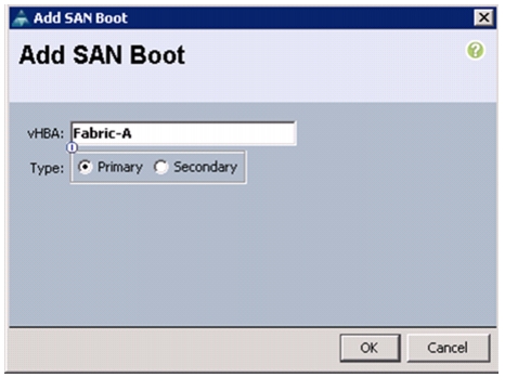
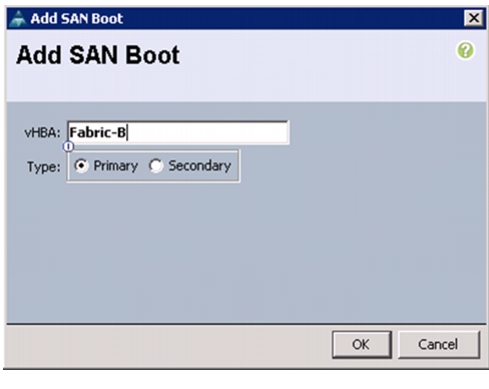
Figure 32 Adding SAN Boot Initiator for Fabric A
13.
14.
15.
Note
16.
17.
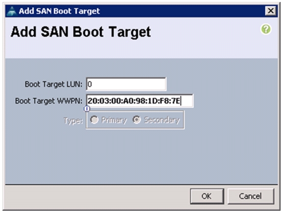
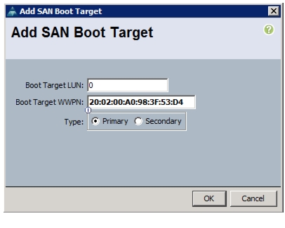
Figure 33 Adding SAN Boot Target for Fabric A
18.
19.
20.
Note
21.
Figure 34 Adding Secondary SAN Boot Target for Fabric A
22.
23.
24.
25.
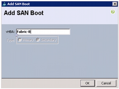
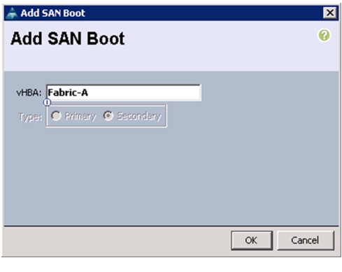
Figure 35 Adding SAN Boot Initiator for Fabric B
26.
27.
28.
Note
29.
30.
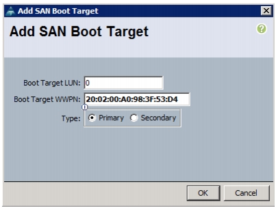
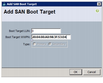
Figure 36 Adding Primary SAN Boot Target for Fabric B
31.
32.
33.
Note
34.
Figure 37 Adding Secondary SAN Boot Target
35.
36.
37.
38.
39.
40.
41.
42.
43.
44.
45.
Figure 38 Adding SAN Boot Initiator for Fabric B
46.
47.
48.
Note
49.
50.
Figure 39 Adding Primary SAN Boot Target for Fabric B
51.
52.
53.
Note
54.
Figure 40 Adding Secondary SAN Boot Target for Fabric B
55.
56.
57.
58.
Figure 41 Adding SAN Boot for Fabric A
59.
60.
61.
Note
62.
63.
Figure 42 Adding Primary SAN Boot Target for Fabric A
64.
65.
66.
Note
67.
Figure 43 Adding Secondary SAN Boot Target for Fabric A
68.
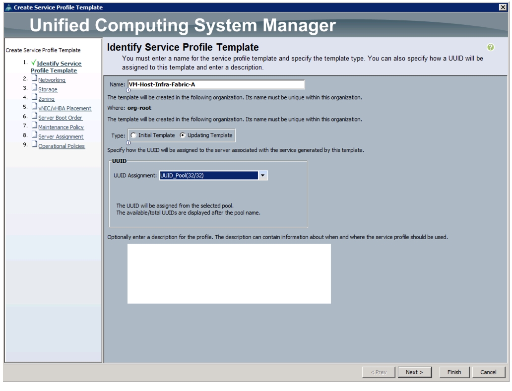
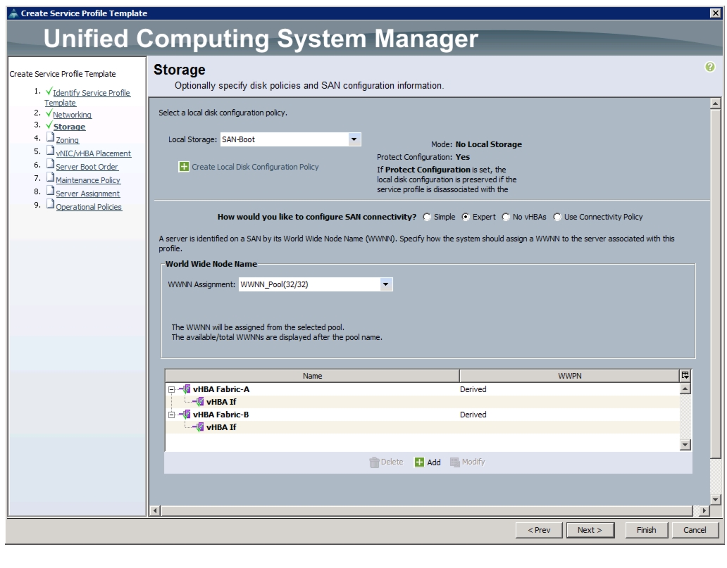
Create Service Profile Templates
In this procedure, two service profile templates are created: one for fabric A boot and one for fabric B boot. The first profile is created and then cloned and modified for the second host.
To create service profile templates, follow these steps:
1.
2.
3.
4.
5.
a.
b.
c.
d.
Figure 44 Details for Creating Service Profile Template
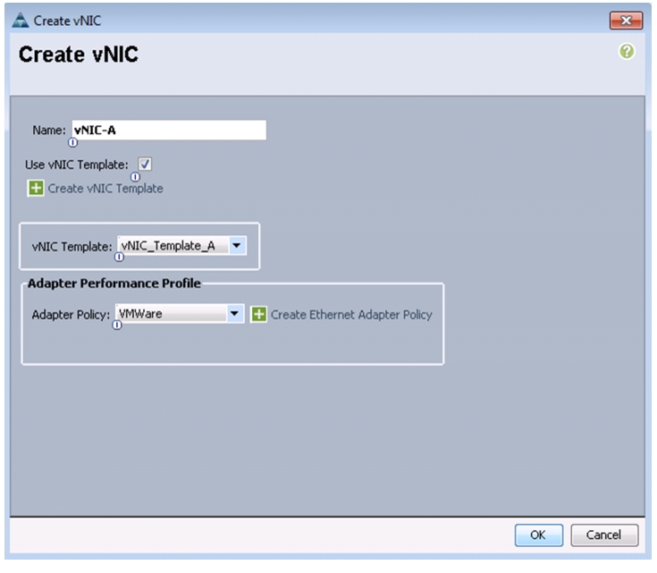
6.
a.
b.
c.
d.
e.
f.
g.
h.
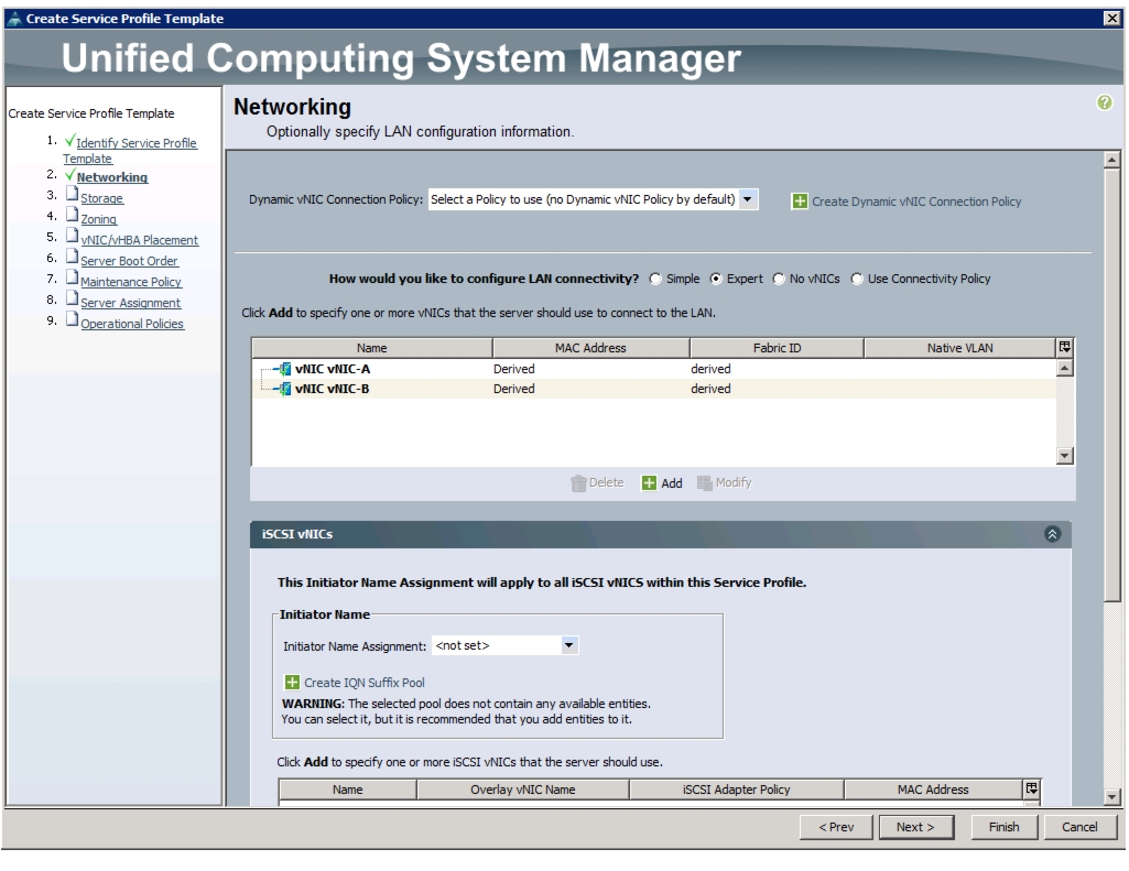
Figure 45 Creating vNIC Using vNIC Template
i.
j.
k.
l.
m.
n.
o.
p.
Figure 46 LAN Configuration Details
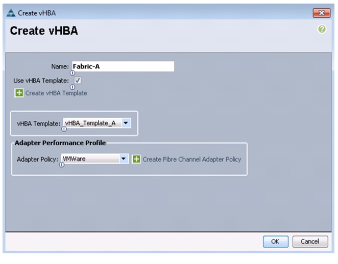
7.
a.
–
–
b.
c.
d.
e.
f.
g.
h.
i.
Figure 47 Creating vHBA Using vHBA Template
j.
k.
l.
m.
n.
o.
p.
q.
Figure 48 Storage Window Showing Created vHBAs
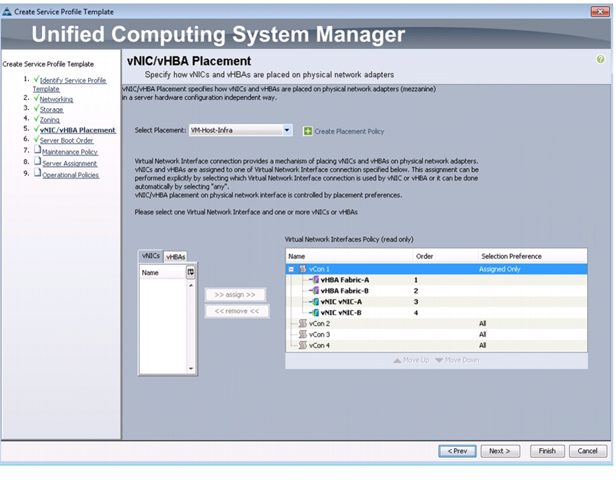
8.
9.
a.
b.
–
–
–
–
c.
d.
Figure 49 Placing vNIC and vHBA on Physical Adapters
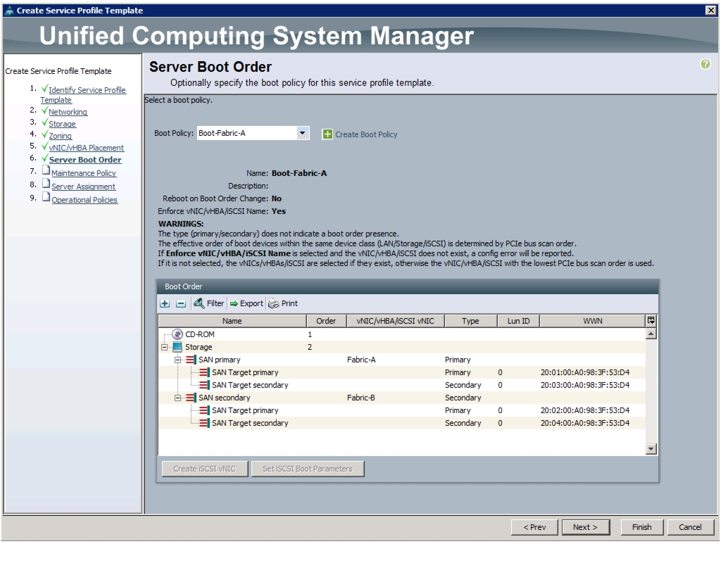
10.
a.
b.
c.
Figure 50 Setting Boot Order for the Service Profile Template
11.
a.
b.
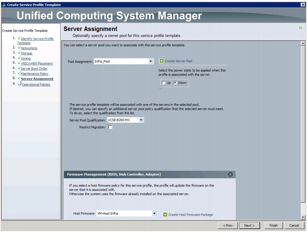
12.
a.
b.
c.
d.
e.
Figure 51 Assigning a Server Pool to the Service Profile Template
13.
a.
b.
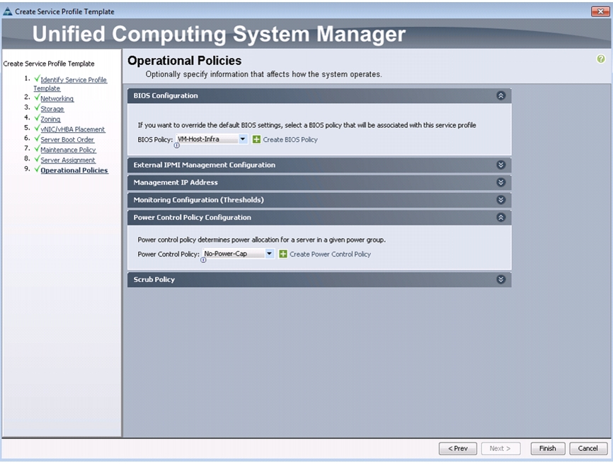
Figure 52 Setting Operational Policy
14.
15.
16.
17.
18.
19.
20.
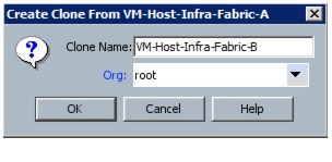
Figure 53 Cloning a Service Profile Template
21.
22.
23.
24.
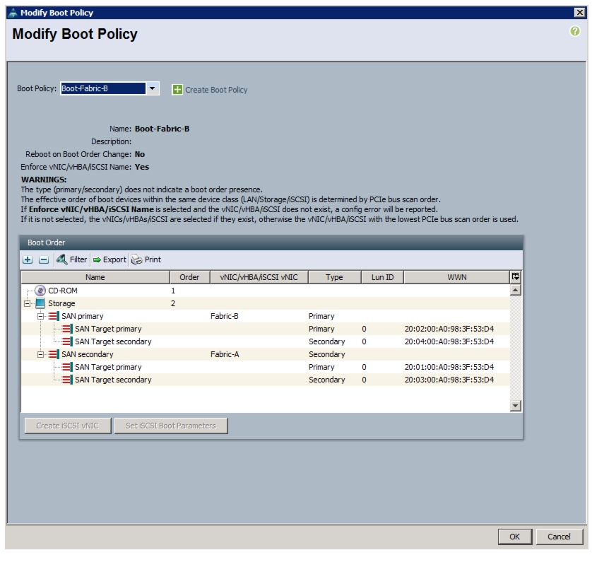
Figure 54 Modifying Boot Policy
25.
26.
27.
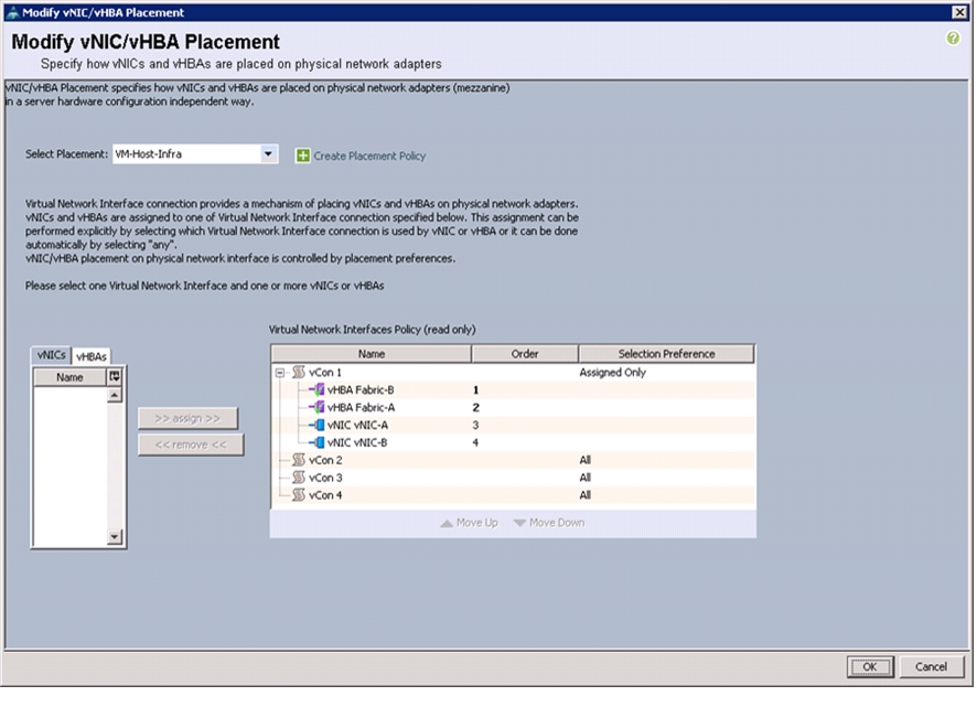
Figure 55 Modifying Placement Policy
28.
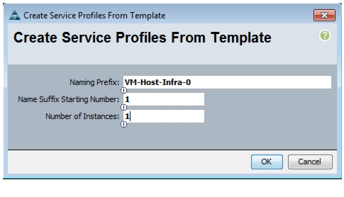
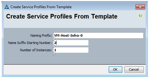
Create Service Profiles
To create service profiles from the service profile template, follow these steps:
1.
2.
3.
4.
5.
6.
7.
Figure 56 Creating Service Profile from a Service Profile Template
8.
9.
10.
11.
12.
13.
14.
Figure 57 Creating Service Profile from a Service Profile Template
15.
Verify that the service profiles VM-Host-Infra-01 and VM-Host-Infra-02 have been created. The service profiles are automatically associated with the servers in their assigned server pools.
16.
Add More Servers to FlexPod Unit
Additional server pools, service profile templates, and service profiles can be created in the respective organizations to add more servers to the FlexPod unit. All other pools and policies are at the root level and can be shared among the organizations.
Gather Necessary Information
After the Cisco UCS service profiles have been created, each infrastructure blade in the environment will have a unique configuration. To proceed with the FlexPod deployment, specific information must be gathered from each Cisco UCS blade and from the NetApp controllers. Insert the required information into Table 28 and Table 29.
Note
Table 29 vHBA WWPNs for Fabric A and Fabric B
VM-Host-infra-01
VM-Host-infra-02
Note
Storage Networking
FlexPod Cisco Nexus Base
Table 30 Flexpod Cisco Nexus Base Prerequisite
The Cisco Nexus switch must be running Cisco Nexus NX-OS 6.0(2)N2(2) or late
The following procedures describe how to configure the Cisco Nexus switches for use in a base FlexPod environment. Follow these steps precisely; failure to do so might result in an improper configuration.
Set Up Initial Configuration
Cisco Nexus A
To set up the initial configuration for the Cisco Nexus A switch on <<var_nexus_A_hostname>>, follow these steps:
1.
Note
Abort Power on Auto Provisioning and continue with normal setup? (yes/no) [no]:
yes
Do you want to enforce secure password standard (yes/no): yesEnter the password for the "admin": <<var_password>>Confirm the password for "admin": <<var_password>>Would you like to enter the basic configuration dialog (yes/no): yesCreate another login account (yes/no) [n]: EnterConfigure read-only SNMP community string (yes/no) [n]: EnterConfigure read-write SNMP community string (yes/no) [n]: EnterEnter the switch name: <<var_nexus_A_hostname>>Continue with out-of-band (mgmt0) management configuration? (yes/no) [y]: EnterMgmt0 IPv4 address: <<var_nexus_A_mgmt0_ip>>Mgmt0 IPv4 netmask: <<var_nexus_A_mgmt0_netmask>>Configure the default gateway? (yes/no) [y]: EnterIPv4 address of the default gateway: <<var_nexus_A_mgmt0_gw>>Enable the telnet service? (yes/no) [n]: EnterEnable the ssh service? (yes/no) [y]: EnterType of ssh key you would like to generate (dsa/rsa): rsaNumber of key bits <768-2048> : 1024Configure the ntp server? (yes/no) [n]: yNTP server IPv4 address: <<var_global_ntp_server_ip>>Enter basic FC configurations (yes/no) [n]: EnterWould you like to edit the configuration? (yes/no) [n]: Enter2.
Use this configuration and save it? (yes/no) [y]: EnterCisco Nexus B
To set up the initial configuration for the Cisco Nexus B switch on <<var_nexus_B_hostname>>, follow these steps:
1.
Note
Abort Power on Auto Provisioning and continue with normal setup? (yes/no) [n]: yesDo you want to enforce secure password standard (yes/no): yesEnter the password for "admin": <<var_password>>Confirm the password for "admin": <<var_password>>Would you like to enter the basic configuration dialog (yes/no): yesCreate another login account (yes/no) [n]: EnterConfigure read-only SNMP community string (yes/no) [n]: EnterConfigure read-write SNMP community string (yes/no) [n]: EnterEnter the switch name: <<var_nexus_B_hostname>>Continue with Out-of-band (mgmt0) management configuration? (yes/no) [y]: EnterMgmt0 IPv4 address: <<var_nexus_B_mgmt0_ip>>Mgmt0 IPv4 netmask: <<var_nexus_B_mgmt0_netmask>>Configure the default gateway? (yes/no) [y]: EnterIPv4 address of the default gateway: <<var_nexus_B_mgmt0_gw>>Enable the telnet service? (yes/no) [n]: EnterEnable the ssh service? (yes/no) [y]: EnterType of ssh key you would like to generate (dsa/rsa): rsaNumber of key bits <768-2048> : 1024Configure the ntp server? (yes/no) [n]: yNTP server IPv4 address: <<var_global_ntp_server_ip>>Enter basic FC configurations (yes/no) [n]: EnterWould you like to edit the configuration? (yes/no) [n]: Enter2.
Use this configuration and save it? (yes/no) [y]: EnterFlexPod Cisco Nexus FCoE Storage vSphere on Clustered Data ONTAP
Enable Licenses
Cisco Nexus A
To license the Cisco Nexus A switch on <<var_nexus_A_hostname>>, follow these steps:
1.
2.
config tfeature fcoefeature npivfeature lacpfeature vpcCisco Nexus B
To license the Cisco Nexus B switch on <<var_nexus_B_hostname>>, follow these steps:
1.
2.
config tfeature fcoefeature npivfeature lacpfeature vpcSet Global Configurations
Cisco Nexus 5548 A and Cisco Nexus 5548 B
To set global configurations, follow these steps on both switches:
Run the following commands to set global configurations and jumbo frames in QoS:
spanning-tree port type network defaultspanning-tree port type edge bpduguard defaultport-channel load-balance ethernet source-dest-portpolicy-map type network-qos jumboclass type network-qos class-defaultmtu 9216exitclass type network-qos class-fcoepause no-dropmtu 2158exitexitsystem qosservice-policy type network-qos jumboexitcopy run startCreate VLANs
Cisco Nexus 5548 A and Cisco Nexus 5548 B
To create the necessary virtual local area networks (VLANs), follow these steps on both switches:
From the global configuration mode, run the following commands:
vlan <<var_ib-mgmt_vlan_id>>name IB-MGMT-VLANexitvlan <<var_native_vlan_id>>name Native-VLANexitvlan <<var_nfs_vlan_id>>name NFS-VLANexitvlan <<var_pkt-ctrl_vlan_id>>name Packet-Control-VLANexitvlan <<var_vmotion_vlan_id>>name vMotion-VLANexitvlan <<var_vm-traffic_vlan_id>>name VM-Traffic-VLANexitAdd Individual Port Descriptions for Troubleshooting
Cisco Nexus 5548 A
To add individual port descriptions for troubleshooting activity and verification for switch A, follow these steps:
From the global configuration mode, run the following commands:
interface Eth1/1description <<var_node01>>:e3aexitinterface Eth1/2description <<var_node02>>:e3aexitinterface Eth1/11description <<var_ucs_clustername>>-A:1/19exitinterface Eth1/12description <<var_ucs_clustername>>-B:1/19exitinterface Eth1/13description <<var_nexus_B_hostname>>:1/13exitinterface Eth1/14description <<var_nexus_B_hostname>>:1/14exitinterface eth1/31description <<var_ucs_clustername>>-A:1/31exitinterface eth1/32description <<var_ucs_clustername>>-A:1/32exitCisco Nexus 5548 B
To add individual port descriptions for troubleshooting activity and verification for switch B, follow these steps:
From the global configuration mode, run the following commands:
interface Eth1/1description <<var_node01>>:e4aexitinterface Eth1/2description <<var_node02>>:e4aexitinterface Eth1/11description <<var_ucs_clustername>>-A:1/20exitinterface Eth1/12description <<var_ucs_clustername>>-B:1/20exitinterface Eth1/13description <<var_nexus_A_hostname>>:1/13exitinterface Eth1/14description <<var_nexus_A_hostname>>:1/14exitinterface eth1/31description <<var_ucs_clustername>>-B:1/31exitinterface eth1/32description <<var_ucs_clustername>>-B:1/32exitCreate Port Channels
Cisco Nexus 5548 A and Cisco Nexus 5548 B
To create the necessary port channels between devices, follow these steps on both switches:
From the global configuration mode, run the following commands:
interface Po10description vPC peer-linkexitinterface Eth1/13-14channel-group 10 mode activeno shutdownexitinterface Po11description <<var_node01>>exitinterface Eth1/1channel-group 11 mode activeno shutdownexitinterface Po12description <<var_node02>>exitinterface Eth1/2channel-group 12 mode activeno shutdownexitinterface Po13description <<var_ucs_clustername>>-Aexitinterface Eth1/11channel-group 13 mode activeno shutdownexitinterface Po14description <<var_ucs_clustername>>-Bexitinterface Eth1/12channel-group 14 mode activeno shutdownexitcopy run startConfigure Port Channels
Cisco Nexus 5548 A and Cisco Nexus 5548 B
To configure the port channels, follow these steps on both switches:
From the global configuration mode, run the following commands:
interface Po10switchport mode trunkswitchport trunk native vlan <<var_native_vlan_id>>switchport trunk allowed vlan <<var_ib-mgmt_vlan_id>>, <<var_nfs_vlan_id>>, <<var_pkt-ctrl_vlan_id>>, <<var_vmotion_vlan_id>>, <<var_vm-traffic_vlan_id>>spanning-tree port type networkno shutdownexitinterface Po11switchport mode trunkswitchport trunk native vlan <<var_native_vlan_id>>switchport trunk allowed vlan <<var_nfs_vlan_id>>spanning-tree port type edge trunkno shutdownexitinterface Po12switchport mode trunkswitchport trunk native vlan <<var_native_vlan_id>>switchport trunk allowed vlan <<var_nfs_vlan_id>>spanning-tree port type edge trunkno shutdownexitinterface Po13switchport mode trunkswitchport trunk native vlan <<var_native_vlan_id>>switchport trunk allowed vlan <<var_ib-mgmt_vlan_id>>, <<var_nfs_vlan_id>>, <<var_vmotion_vlan_id>>, <<var_vm-traffic_vlan_id>>spanning-tree port type edge trunkno shutdownexitinterface Po14switchport mode trunkswitchport trunk native vlan <<var_native_vlan_id>>switchport trunk allowed vlan<<var_ib-mgmt_vlan_id>>, <<var_nfs_vlan_id>>, <<var_vmotion_vlan_id>>, <<var_vm-traffic_vlan_id>>spanning-tree port type edge trunkno shutdownexitcopy run startConfigure Virtual Port Channels
Cisco Nexus 5548 A
To configure virtual port channels (vPCs) for switch A, follow these steps:
From the global configuration mode, run the following commands:
vpc domain <<var_nexus_vpc_domain_id>>role priority 10peer-keepalive destination <<var_nexus_B_mgmt0_ip>> source <<var_nexus_A_mgmt0_ip>>auto-recoveryexitinterface Po10vpc peer-linkexitinterface Po11vpc 11exitinterface Po12vpc 12exitinterface Po13vpc 13exitinterface Po14vpc 14exitcopy run startCisco Nexus 5548 B
To configure vPCs for switch B, follow these steps:
From the global configuration mode, run the following commands.
vpc domain <<var_nexus_vpc_domain_id>>role priority 20peer-keepalive destination <<var_nexus_A_mgmt0_ip>> source <<var_nexus_B_mgmt0_ip>>auto-recoveryexitinterface Po10vpc peer-linkexitinterface Po11vpc 11exitinterface Po12vpc 12exitinterface Po13vpc 13exitinterface Po14vpc 14exitcopy run startConfigure Ports for Cisco Nexus 1110-X Virtual Appliances
Cisco Nexus 5548 A
To configure the ports in switch A that are connected to the Cisco Nexus 1110-X, follow these steps:
From the global configuration mode, run the following commands:
interface Eth1/15description <<var_nexus_1110x-1>>:Eth1switchport mode trunkswitchport trunk allowed vlan <<var_ib-mgmt_vlan_id>>, <<var_pkt-ctrl_vlan_id>>speed 1000spanning-tree port type edge trunkno shutdownexitinterface Eth1/16description <<var_nexus_1110x-2>>:Eth1switchport mode trunkswitchport trunk allowed vlan <<var_ib-mgmt_vlan_id>>, <<var_pkt-ctrl_vlan_id>>speed 1000spanning-tree port type edge trunkno shutdownexitcopy run startCisco Nexus 5548 B
To configure the ports in switch B that are connected to the Cisco Nexus 1110-X, follow these steps:
From the global configuration mode, run the following commands:
interface Eth1/15description <<var_nexus_1110x-1>>:Eth2switchport mode trunkswitchport trunk allowed vlan <<var_ib-mgmt_vlan_id>>, <<var_pkt-ctrl_vlan_id>>speed 1000spanning-tree port type edge trunkno shutdownexitinterface Eth1/16description <<var_nexus_1110x-2>>:Eth2switchport mode trunkswitchport trunk allowed vlan <<var_ib-mgmt_vlan_id>>, <<var_pkt-ctrl_vlan_id>>speed 1000spanning-tree port type edge trunkno shutdownexitcopy run startUplink into Existing Network Infrastructure
Depending on the available network infrastructure, several methods and features can be used to uplink the FlexPod environment. If an existing Cisco Nexus environment is present, NetApp recommends using vPCs to uplink the Cisco Nexus 5548 switches included in the FlexPod environment into the infrastructure. The previously described procedures can be used to create an uplink vPC to the existing environment. Make sure to run the copy run start command to save the configuration on each switch after configuration is completed.
Create VSANs, Assign and Enable Virtual Fibre Channel Ports
This procedure sets up Fibre Channel over Ethernet (FCoE) connections between the Cisco Nexus 5548UP switches, the Cisco UCS Fabric Interconnects, and the NetApp storage systems.
Cisco Nexus 5548 A
To configure virtual storage area networks (VSANs), assign virtual Fibre Channel (vFC) ports, and enable vFC ports on switch A, follow these steps:
From the global configuration mode, run the following commands:
vlan <<var_fabric_a_fcoe_vlan_id>>name FCoE_Fabric_Afcoe vsan <<var_vsan_a_id>>exitinterface po11switchport trunk allowed vlan add <<var_fabric_a_fcoe_vlan_id>>exitinterface vfc11switchport description <<var_node01>>:3abind interface Eth1/1switchport trunk allowed vsan <<var_vsan_a_id>>no shutdownexitinterface po12switchport trunk allowed vlan add <<var_fabric_a_fcoe_vlan_id>>exitinterface vfc12switchport description <<var_node02>>:3abind interface Eth1/2switchport trunk allowed vsan <<var_vsan_a_id>>no shutdownexitinterface po15description <<var_ucs_clustername>>-A:FCoEexitinterface Eth1/31-32channel-group 15 mode activeexitinterface po15switchport mode trunkswitchport trunk native vlan <<var_native_vlan_id>>switchport trunk allowed vlan <<var_fabric_a_fcoe_vlan_id>>spanning-tree port type edge trunkno shutdownexitinterface vfc15switchport description <<var_ucs_clustername>>-A:FCoEbind interface po15switchport trunk allowed vsan <<var_vsan_a_id>>no shutdownvsan databasevsan <<var_vsan_a_id>> name Fabric_Avsan <<var_vsan_a_id>> interface vfc11vsan <<var_vsan_a_id>> interface vfc12vsan <<var_vsan_a_id>> interface vfc15exitCisco Nexus 5548 B
To configure VSANs, assign vFC ports, and enable vFC ports on switch B, follow these steps:
From the global configuration mode, run the following commands:
vlan <<var_fabric_b_fcoe_vlan_id>>name FCoE_Fabric_Bfcoe vsan <<var_vsan_b_id>>exitinterface po11switchport trunk allowed vlan add <<var_fabric_b_fcoe_vlan_id>>exitinterface vfc11switchport description <<var_node01>>:4abind interface Eth1/1switchport trunk allowed vsan <<var_vsan_b_id>>no shutdownexitinterface po12switchport trunk allowed vlan add <<var_fabric_b_fcoe_vlan_id>>exitinterface vfc12switchport description <<var_node02>>:4abind interface Eth1/2switchport trunk allowed vsan <<var_vsan_b_id>>no shutdownexitinterface po15description <<var_ucs_clustername>>-B:FCoEexitinterface Eth1/31-32channel-group 15 mode activeexitinterface po15switchport mode trunkswitchport trunk native vlan <<var_native_vlan_id>>switchport trunk allowed vlan <<var_fabric_b_fcoe_vlan_id>>spanning-tree port type edge trunkno shutdownexitinterface vfc15switchport description <<var_ucs_clustername>>-B:FCoEbind interface po15switchport trunk allowed vsan <<var_vsan_b_id>>no shutdownvsan databasevsan <<var_vsan_b_id>> name Fabric_Bvsan <<var_vsan_b_id>> interface vfc11vsan <<var_vsan_b_id>> interface vfc12vsan <<var_vsan_b_id>> interface vfc15exitCreate Device Aliases
Cisco Nexus 5548 A
To configure device aliases and zones for the primary boot paths of switch A on <<var_nexus_A_hostname>>, follow these steps:
From the global configuration mode, run the following commands:
device-alias databasedevice-alias name VM-Host-Infra-01_A pwwn <<var_vm_host_infra_01_A_wwpn>>device-alias name VM-Host-Infra-02_A pwwn <<var_vm_host_infra_02_A_wwpn>>device-alias name fcp_lif01a pwwn <<var_fcp_lif01a_wwpn>>device-alias name fcp_lif02a pwwn <<var_fcp_lif02a_wwpn>>exitdevice-alias commitCisco Nexus 5548 B
To configure device aliases and zones for the boot paths of switch B on <<var_nexus_B_hostname>>, follow these steps:
From the global configuration mode, run the following commands:
device-alias databasedevice-alias name VM-Host-Infra-01_B pwwn <<var_vm_host_infra_01_B_wwpn>>device-alias name VM-Host-Infra-02_B pwwn <<var_vm_host_infra_02_B_wwpn>>device-alias name fcp_lif01b pwwn <<var_fcp_lif01b_wwpn>>device-alias name fcp_lif02b pwwn <<var_fcp_lif02b_wwpn>>exitdevice-alias commitCreate Zones
Cisco Nexus 5548 A
To create zones for the service profiles on switch A, follow these steps:
1.
zone name VM-Host-Infra-01_A vsan <<var_vsan_a_id>>member device-alias VM-Host-Infra-01_Amember device-alias fcp_lif01amember device-alias fcp_lif02aexitzone name VM-Host-Infra-02_A vsan <<var_vsan_a_id>>member device-alias VM-Host-Infra-02_Amember device-alias fcp_lif01amember device-alias fcp_lif02aexit2.
zoneset name FlexPod vsan <<var_vsan_a_id>>member VM-Host-Infra-01_Amember VM-Host-Infra-02_Aexit3.
zoneset activate name FlexPod vsan <<var_vsan_a_id>>exitcopy run startCisco Nexus 5548 B
To create zones for the service profiles on switch B, follow these steps:
1.
zone name VM-Host-Infra-01_B vsan <<var_vsan_b_id>>member device-alias VM-Host-Infra-01_Bmember device-alias fcp_lif01bmember device-alias fcp_lif02bexitzone name VM-Host-Infra-02_B vsan <<var_vsan_b_id>>member device-alias VM-Host-Infra-02_Bmember device-alias fcp_lif01bmember device-alias fcp_lif02bexit2.
zoneset name FlexPod vsan <<var_vsan_b_id>>member VM-Host-Infra-01_Bmember VM-Host-Infra-02_Bexit3.
zoneset activate name FlexPod vsan <<var_vsan_b_id>>exitcopy run startStorage Part 2
Clustered Data ONTAP SAN Boot Storage Setup
Create Igroups
From the cluster management node SSH connection, enter the following:
igroup create -vserver Infra_Vserver -igroup VM-Host-Infra-01 -protocol fcp -ostype
vmware -initiator <<var_vm_host_infra_01_A_wwpn>>, <<var_vm_host_infra_01_B_wwpn>>
igroup create -vserver Infra_Vserver -igroup VM-Host-Infra-02 -protocol fcp -ostype vmware -initiator <<var_vm_host_infra_02_A_wwpn>>, <<var_vm_host_infra_02_B_wwpn>>igroup create -vserver Infra_Vserver -igroup MGMT-Hosts -protocol fcp -ostype vmware -initiator <<var_vm_host_infra_01_A_wwpn>>, <<var_vm_host_infra_01_B_wwpn>>, <<var_vm_host_infra_02_A_wwpn>>, <<var_vm_host_infra_02_B_wwpn>>
Note
Map Boot LUNs to Igroups
From the cluster management SSH connection, enter the following:
lun map -vserver Infra_Vserver -volume esxi_boot -lun VM-Host-Infra-01 -igroup
VM-Host-Infra-01 -lun-id 0
lun map -vserver Infra_Vserver -volume esxi_boot -lun VM-Host-Infra-02 -igroup VM-Host-Infra-02 -lun-id 0VMware vSphere 5.1Update1 Setup
FlexPod VMware ESXi 5.1Update1 FCoE on Clustered Data ONTAP
This section provides detailed instructions for installing VMware ESXi 5.1Update1 in a FlexPod environment. After the procedures are completed, two FCP-booted ESXi hosts will be provisioned. These deployment procedures are customized to include the environment variables.
Note
Log in to Cisco UCS 6200 Fabric Interconnect
Cisco UCS Manager
The IP KVM enables the administrator to begin the installation of the operating system (OS) through remote media. It is necessary to log in to the UCS environment to run the IP KVM.
To log in to the Cisco UCS environment, follow these steps:
1.
2.
3.
4.
5.
6.
7.
8.
9.
10.
11.
12.
Set Up VMware ESXi Installation
ESXi Hosts VM-Host-Infra-01 and VM-Host-Infra-02
To prepare the server for the OS installation, follow these steps on each ESXi host:
1.
2.
3.
4.
5.
6.
Install ESXi
ESXi Hosts VM-Host-Infra-01 and VM-Host-Infra-02
To install VMware ESXi to the SAN-bootable LUN of the hosts, follow these steps on each host:
1.
2.
3.
4.
5.
6.
7.
8.
Note
9.
10.
Set Up Management Networking for ESXi Hosts
Adding a management network for each VMware host is necessary for managing the host. To add a management network for the VMware hosts, follow these steps on each ESXi host:
ESXi Host VM-Host-Infra-01
To configure the VM-Host-Infra-01 ESXi host with access to the management network, follow these steps:
1.
2.
3.
4.
5.
6.
7.
8.
9.
10.
11.
12.
13.
14.
Note
15.
16.
17.
18.
19.
20.
21.
22.
23.
24.
25.
ESXi Host VM-Host-Infra-02
To configure the VM-Host-Infra-02 ESXi host with access to the management network, follow these steps:
1.
2.
3.
4.
5.
6.
7.
8.
9.
10.
11.
12.
13.
14.
Note
15.
16.
17.
18.
19.
20.
21.
22.
23.
24.
25.
Download VMware vSphere Client and vSphere Remote CLI
To download the VMware vSphere Client and install Remote CLI, follow these steps:
1.
2.
Note
Log in to VMware ESXi Hosts by Using VMware vSphere Client
ESXi Host VM-Host-Infra-01
To log in to the VM-Host-Infra-01 ESXi host by using the VMware vSphere Client, follow these steps:
1.
2.
3.
4.
ESXi Host VM-Host-Infra-02
To log in to the VM-Host-Infra-02 ESXi host by using the VMware vSphere Client, follow these steps:
1.
2.
3.
4.
Download Updated Cisco VIC enic and fnic Drivers
To download the Cisco virtual interface card (VIC) enic and fnic drivers, follow these steps:
Note
1.
–
–
2.
3.
a.
Network: Cisco_bootbank_net-enic_2.1.2.38-1OEM.500.0.0.472560.vib
b.
Storage: Cisco_bootbank_scsi-fnic_1.5.0.45-1OEM.500.0.0.472560.vib
4.
Load Updated Cisco VIC enic and fnic Drivers
ESXi Hosts VM-Host-Infra-01 and VM-Host-Infra-02
To load the updated versions of the enic and fnic drivers for the Cisco VIC, follow these steps for the hosts on each vSphere Client:
1.
2.
3.
4.
5.
6.
7.
8.
9.
10.
11.
12.
13.
esxcli -s <<var_vm_host_infra_01_ip>> -u root -p <<var_password>> software vib
install --no-sig-check -v
/vmfs/volumes/datastore1/Cisco_bootbank_net-enic_2.1.2.38-1OEM.500.0.0.472560.vib
esxcli -s <<var_vm_host_infra_02_ip>> -u root -p <<var_password>> software vib install --no-sig-check -v /vmfs/volumes/datastore1/Cisco_bootbank_net-enic_2.1.2.38-1OEM.500.0.0.472560.vib14.
esxcli -s <<var_vm_host_infra_01_ip>> -u root -p <<var_password>> software vib
install --no-sig-check -v
/vmfs/volumes/datastore1/Cisco_bootbank_scsi-fnic_1.5.0.45-1OEM.500.0.0.472560.vib
esxcli -s <<var_vm_host_infra_02_ip>> -u root -p <<var_password>> software vib install --no-sig-check -v /vmfs/volumes/datastore1/Cisco_bootbank_scsi-fnic_1.5.0.45-1OEM.500.0.0.472560.vib15.
16.
17.
18.
Set Up VMkernel Ports and Virtual Switch
ESXi Host VM-Host-Infra-01
To set up the VMkernel ports and the virtual switches on the VM-Host-Infra-01 ESXi host, follow these steps:
1.
2.
3.
4.
5.
6.
7.
8.
9.
10.
11.
12.
13.
14.
15.
16.
17.
18.
19.
20.
21.
22.
23.
24.
25.
26.
27.
28.
29.
30.
31.
32.
33.
34.
35.
Figure 58 vSphere Client Showing VMKernel Ports and Virtual Switch
ESXi Host VM-Host-Infra-02
To set up the VMkernel ports and the virtual switches on the VM-Host-Infra-02 ESXi host, follow these steps:
1.
2.
3.
4.
5.
6.
7.
8.
9.
10.
11.
12.
13.
14.
15.
16.
17.
18.
19.
20.
21.
22.
23.
24.
25.
26.
27.
28.
29.
30.
31.
32.
33.
34.
35.
Figure 59 vSphere Client Showing VMKernel Ports and Virtual Switch
Mount Required Datastores
ESXi Hosts VM-Host-Infra-01 and VM-Host-Infra-02
To mount the required datastores, follow these steps on each ESXi host:
1.
2.
3.
4.
5.
6.
7.
8.
9.
10.
11.
12.
13.
14.
15.
16.
17.
18.
19.
Configure NTP on ESXi Hosts
ESXi Hosts VM-Host-Infra-01 and VM-Host-Infra-02
To configure Network Time Protocol (NTP) on the ESXi hosts, follow these steps on each host:
1.
2.
3.
4.
5.
6.
a.
b.
7.
8.
9.
a.
b.
Note
Move VM Swap File Location
ESXi Hosts VM-Host-Infra-01 and VM-Host-Infra-02
To move the VM swap file location, follow these steps on each ESXi host:
1.
2.
3.
4.
5.
6.
7.
FlexPod VMware vCenter 5.1Update1
The procedures in the following subsections provide detailed instructions for installing VMware vCenter 5.1 in a FlexPod environment. After the procedures are completed, a VMware vCenter Server will be configured along with a Microsoft SQL Server database to provide database support to vCenter. These deployment procedures are customized to include the environment variables.
Note
To install VMware vCenter 5.1, an accessible Windows Active Directory® (AD) Domain is necessary. If an existing AD Domain is not available, an AD virtual machine, or AD pair, can be set up in this FlexPod environment. See "Appendix" section for this setup.
Build Microsoft SQL Server VM
ESXi Host VM-Host-Infra-01
To build a SQL Server virtual machine (VM) for the VM-Host-Infra-01 ESXi host, follow these steps:
1.
2.
3.
4.
5.
6.
7.
8.
9.
10.
11.
12.
13.
14.
15.
16.
17.
18.
19.
20.
21.
22.
23.
24.
25.
26.
27.
28.
29.
30.
31.
32.
33.
34.
35.
36.
37.
38.
39.
40.
41.
42.
43.
44.
Note
45.
46.
Note
Install Microsoft SQL Server 2008 R2
vCenter SQL Server VM
To install SQL Server on the vCenter SQL Server VM, follow these steps:
1.
2.
3.
4.
Figure 60 Adding Features for Installing SQL Server
5.
6.
7.
8.
9.
10.
11.
12.
13.
14.
15.
16.
17.
18.
19.
20.
21.
22.
23.
24.
Note
25.
26.
27.
Figure 61 Selecting SQL Server Features
28.
29.
Figure 62 SQL Server Instance Configuration
30.
31.
32.
33.
34.
35.
Figure 63 Configuring SQL Server
36.
Figure 64 Configuring Database Engine
37.
38.
39.
40.
41.
42.
43.
44.
45.
46.
use [master]goCREATE DATABASE [VCDB] ON PRIMARY(NAME = N'vcdb', FILENAME = N'C:\VCDB.mdf', SIZE = 2000KB, FILEGROWTH = 10% )LOG ON(NAME = N'vcdb_log', FILENAME = N'C:\VCDB.ldf', SIZE = 1000KB, FILEGROWTH = 10%)COLLATE SQL_Latin1_General_CP1_CI_ASgouse VCDBgosp_addlogin @loginame=[vpxuser], @passwd=N'<Password>', @defdb='VCDB',@deflanguage='us_english'goALTER LOGIN [vpxuser] WITH CHECK_POLICY = OFFgoCREATE USER [vpxuser] for LOGIN [vpxuser]gouse MSDBgoCREATE USER [vpxuser] for LOGIN [vpxuser]gouse VCDBgosp_addrolemember @rolename = 'db_owner', @membername = 'vpxuser'gouse MSDBgosp_addrolemember @rolename = 'db_owner', @membername = 'vpxuser'go
Note
Figure 65 Executing the Query
47.
48.
49.
Build and Set Up VMware vCenter VM
Build VMware vCenter VM
To build the VMware vCenter VM, follow these steps:
1.
–
–
–
2.
Set Up VMware vCenter VM
To set up the newly built VMware vCenter VM, follow these steps:
1.
2.
3.
4.
5.
6.
7.
8.
9.
10.
11.
12.
13.
Figure 66 Creating New Data Source
14.
Figure 67 Login Credentials for SQL Server
15.
Figure 68 Setting Up the Database
16.
17.
Figure 69 Verifying ODBC Data Source
18.
19.
20.
Note
Install VMware vCenter Server
vCenter Server VM
To install vCenter Server on the vCenter Server VM, follow these steps:
1.
2.
3.
4.
Figure 70 Installing VMware vSphere
5.
6.
7.
8.
9.
10.
Figure 71 Setting Database User Information
11.
12.
13.
14.
15.
16.
17.
18.
19.
20.
Figure 72 Selecting Database for VMware vSphere
21.
Figure 73 Entering Database Login Credentials
22.
23.
24.
25.
26.
27.
28.
29.
30.
31.
Note
Set Up vCenter Server
vCenter Server VM
To set up vCenter Server on the vCenter Server VM, follow these steps:
1.
2.
3.
4.
5.
Figure 74 Selecting Cluster Features
6.
7.
8.
9.
10.
11.
Note
12.
13.
14.
15.
16.
17.
18.
19.
20.
21.
22.
FlexPod Cisco Nexus 1110-X and 1000V vSphere
The following sections provide detailed procedures for installing a pair of high-availability (HA) Cisco Nexus 1110-X Virtual Services Appliances (VSAs) in a FlexPod configuration. Primary and standby Cisco Nexus 1000V Virtual Supervisor Modules (VSMs) are installed on the 1110-Xs. By the end of this section, a Cisco Nexus 1000V distributed virtual switch (DVS) will be provisioned. This procedure assumes that the Cisco Nexus 1000V software version 4.2(1)SV2(1.1a) has been downloaded from www.cisco.com and expanded. This procedure also assumes that VMware vSphere 5.1Update1 Enterprise Plus licensing is installed.
Configure CIMC Interface on Both Cisco Nexus 1110-Xs
Cisco Nexus 1110-X A and Cisco Nexus 1110-X B
To configure the Cisco Integrated Management Controller (CIMC) interface on the Cisco Nexus 1110-X VSAs, follow these steps:
1.
2.
3.
4.
5.
6.
7.
8.
9.
10.
11.
12.
13.
Configure Serial over LAN for Both Cisco Nexus 1110-Xs
Cisco Nexus 1110-X A and Cisco Nexus 1110-X B
To configure serial over LAN on the Cisco Nexus 1110-X VSAs, follow these steps:
1.
2.
3.
4.
5.
6.
7.
Figure 75 Configuring Serial Over LAN on Cisco Nexus 1110-Xs
8.
9.
10.
Figure 76 Execute Command for Connecting the Host
Configure Cisco Nexus 1110-X Virtual Appliances
Cisco Nexus 1110-X A
To configure Cisco Nexus 1110-X A, follow these steps:
1.
Enter the password for "admin": <<var_password>>Confirm the password for "admin": <<var_password>>Enter HA role[primary/secondary]: primaryEnter network-uplink type <1-5>: 1Enter control VLAN <1-3967, 4048-4093>: <<var_pkt-ctrl_vlan_id>>Enter the domain<1-4095>: <<var_1110x_domain_id>>Enter management vlan <1-3967, 4048-4093>: <<var_ib-mgmt_vlan_id>>Would you like to enter the basic system configuration dialogue (yes/no): yesCreate another login account (yes/no) [n]: EnterConfigure read-only SNMP community string (yes/no)[n]: EnterConfigure read-write SNMP community string (yes/no)[n]: EnterEnter the VSA name : <<var_1110x_vsa>>Continue with Out-of-band (mgmt0) management configuration? (yes/no) [y]: EnterMgmt0 IP address type V4/V6? (V4): EnterMgmt0 IPv4 address : <<var_1110x_vsa_ip>>Mgmt0 IPv4 netmask : <<var_1110x_vsa_mask>>Configure the default gateway? (yes/no) [y]: EnterIPv4 address of the default gateway : <<var_1110x_vsa_gateway>>Configure advanced IP options? (yes/no) [n]: EnterEnable the telnet service? (yes/no) [n]: EnterEnable the ssh service? (yes/no) [y]: EnterType of ssh key you would like to generate (das/rsa) [rsa]: EnterNumber of rsa key bits <768-2048> [1024]: EnterEnable the http server? (yes/no) [y]: EnterConfigure the ntp server? (yes/no) [n]: yNTP server IPv4 address: <<var_global_ntp_server_ip>>2.
Would you like to edit the configuration? (yes/no) [n]: EnterUse this configuration and save it? (yes/no) [y]: Enter3.
Cisco Nexus 1110-X B
To configure the Cisco Nexus 1110-X B, follow these steps:
1.
Enter the password for "admin": <<var_password>>Confirm the password for "admin": <<var_password>>
Note
2.
Enter HA role[primary/secondary]: secondaryEnter network-uplink type <1-5>:1. Ports 1-2 carry all management, control and data vlans2. Ports 1-2 management and control, ports 3-6 data3. Ports 1-2 management, ports 3-6 control and data4. Ports 1-2 management, ports 3-4 control, ports 5-6 data5. FlexibleChoose 1Enter control vlan <1-3967, 4048-4093>: <<var_pkt-ctrl_vlan_id>>Enter the domain id<1-4095>: <<var_1110x_domain_id>>
Note
Enter management vlan <1-3967, 4048-4093>: <<var_ib-mgmt_vlan_id>>3.
Set Up the Primary Cisco Nexus 1000V VSM
Cisco Nexus 1110-X A
To set up the primary Cisco Nexus 1000V VSM on the Cisco Nexus 1110-X A, follow these steps:
1.
show module2.
config tvirtual-service-blade VSM-1dir /repository3.
virtual-service-blade-type new nexus-1000v.4.2.1.SV2.1.1a.isointerface control vlan <<var_pkt-ctrl_vlan_id>>interface packet vlan <<var_pkt-ctrl_vlan_id>>enable primaryEnter vsb image:[nexus-1000v.4.2.1.SV2.1.1a.iso] EnterEnter domain id[1-4095]: <<var_vsm_domain_id>>
Note
Enter SVS Control mode (L2 / L3): [L3] EnterManagement IP version [V4/V6]: [V4] EnterEnter Management IP address: <<var_vsm_mgmt_ip>>Enter Management subnet mask: <<var_vsm_mgmt_mask>>IPv4 address of the default gateway: <<var_vsm_mgmt_gateway>>Enter HostName: <<var_vsm_hostname>>Enter the password for 'admin': <<var_password>>copy run start4.
Set Up the Secondary Cisco Nexus 1000V VSM
To set up the secondary Cisco Nexus 1000V VSM on Cisco Nexus 1110-X B, follow these steps in both the subsections:
Cisco Nexus 1110-X A
Run system switchover to activate Cisco Nexus 1110-X B.
Cisco Nexus 1110-X B
1.
config tvirtual-service-blade VSM-1enable secondaryEnter vsb image: [nexus-1000v.4.2.1.SV2.2.1a.iso] EnterEnter domain id[1-4095]: <<var_vsm_domain_id>>Enter SVS Control mode (L2 / L3): [L3] EnterManagement IP version [V4/V6]: [V4] EnterEnter Management IP address: <<var_vsm_ mgmt_ip>>Enter Management subnet mask: <<var_vsm_ mgmt_mask>>IPv4 address of the default gateway: <<var_vsm_mgmt_gateway>>Enter HostName: <<var_vsm_hostname>>Enter the password for 'admin': <<var_password>>2.
copy run start3.
Install Virtual Ethernet Module on Each ESXi Host
vCenter Server Virtual Machine
To install the Virtual Ethernet Module (VEM) on the ESXi hosts, follow these steps:
1.
2.
3.
4.
5.
6.
7.
8.
9.
10.
11.
12.
13.
14.
esxcli -s <Host Server IP> -u root -p <Root Password> software vib install -v
/vmfs/volumes/infra_datastore_1/VEM/cross_cisco-vem-v162-4.2.1.2.2.1a.0-3.1.1.vib
Figure 77 Executing Command for Each ESXi Hosts
Register Cisco Nexus 1000V as a vCenter Plug-in
To register the Cisco Nexus 1000V as a vCenter plug-in, follow these steps:
1.
2.
3.
4.
5.
6.
7.
8.
9.
10.
11.
Perform Base Configuration of the Primary VSM
To perform the base configuration of the primary VSM, follow these steps:
1.
2.
config tsvs connection vCenterprotocol vmware-vimremote ip address <<var_vcenter_server_ip>> port 80vmware dvs datacenter-name FlexPod_DC_1connectexitntp server <<var_global_ntp_server_ip>> use-vrf managementvlan <<var_ib-mgmt_vlan_id>>name IB-MGMT-VLANvlan <<var_nfs_vlan_id>>name NFS-VLANvlan <<var_vmotion_vlan_id>>name vMotion-VLANvlan <<var_vm-traffic_vlan_id>>name VM-Traffic-VLANvlan <<var_native_vlan_id>>name Native-VLANexitport-profile type ethernet system-uplinkvmware port-groupswitchport mode trunkswitchport trunk native vlan <<var_native_vlan_id>>switchport trunk allowed vlan <<var_ib-mgmt_vlan_id>>, <<var_nfs_vlan_id>>, <<var_vmotion_vlan_id>>, <<var_vm-traffic_vlan_id>>channel-group auto mode on mac-pinningno shutdownsystem vlan <<var_mgmt_vlan_id>>, <<var_nfs_vlan_id>>, <<var_vmotion_vlan_id>>, <<var_vm-traffic_vlan_id>>system mtu 9000state enabledport-profile type vethernet IB-MGMT-VLANvmware port-groupswitchport mode accessswitchport access vlan <<var_ib-mgmt_vlan_id>>no shutdownsystem vlan <<var_ib-mgmt_vlan_id>>state enabledport-profile type vethernet NFS-VLANvmware port-groupswitchport mode accessswitchport access vlan <<var_nfs_vlan_id>>no shutdownsystem vlan <<var_nfs_vlan_id>>state enabledport-profile type vethernet vMotion-VLANvmware port-groupswitchport mode accessswitchport access vlan <<var_vmotion_vlan_id>>no shutdownsystem vlan <<var_vmotion_vlan_id>>state enabledport-profile type vethernet VM-Traffic-VLANvmware port-groupswitchport mode accessswitchport access vlan <<var_vm-traffic_vlan_id>>no shutdownsystem vlan <<var_vm-traffic_vlan_id>>state enabledport-profile type vethernet n1kv-L3capability l3controlvmware port-groupswitchport mode accessswitchport access vlan <<var_ib-mgmt_vlan_id>>no shutdownsystem vlan <<var_ib-mgmt_vlan_id>>state enabledexitcopy run startMigrate Networking Components for ESXi Hosts to Cisco Nexus 1000V
vSphere Client Connect to vCenter
To migrate the networking components for the ESXi hosts to the Cisco Nexus 1000V, follow these steps:
1.
2.
3.
4.
Figure 78 Adding Host to the vSphere Distributed Switch
5.
Figure 79 Assigning Port Groups
6.
Figure 80 Choosing Port Groups for Each VMs
7.
8.
9.
10.
11.
12.
13.
14.
15.
16.
17.
18.
19.
20.
21.
22.
23.
24.
25.
Figure 81 Verifying Interfaces and Port Channels
26.
Figure 82 Verifying the ESXi Hosts
27.
28.
FlexPod Management Tool Setup
NetApp Virtual Storage Console (VSC) 4.2.1 Deployment Procedure
VSC 4.2.1 Preinstallation Considerations
The following licenses are required for VSC on storage systems that run clustered Data ONTAP 8.2:
•
•
•
•
Install VSC 4.2.1
To install the VSC 4.1 software, follow these steps:
1.
2.
3.
4.
5.
6.
7.
Note
Figure 83 Selecting the Desired Capabilities of VSC 4.1
8.
Figure 84 Installation Location
9.
Figure 85 Ready to Install VSC 4.1
10.
Register VSC with vCenter Server
To register the VSC with the vCenter Server, follow these steps:
1.
2.
3.
4.
Figure 86 Registering VSC with vCenter Server
Discover and Add Storage Resources
To discover storage resources for the Monitoring and Host Configuration and the Provisioning and Cloning capabilities, follow these steps:
1.
2.
3.
4.
Figure 87 Adding Storage Resource
5.
Figure 88 Certificate Details
6.
Figure 89 vSphere Client Showing Storage Controllers
7.
8.
9.
Optimal Storage Settings for ESXi Hosts
VSC allows for the automated configuration of storage-related settings for all ESXi hosts that are connected to NetApp storage controllers. To use these settings, follow these steps:
1.
2.
Figure 90 Setting Recommended Values for the Hosts
3.
Note
Figure 91 Recommended Settings for NetApp Storage System
4.
Figure 92 ESXi Servers with Changed Network Related Parameter
VSC 4.2.1 Backup and Recovery
Prerequisites to use Backup and Recovery Capability
You can use the Backup and Recovery capability to schedule backups and restore your datastores, virtual machines, or virtual disk files. Before you begin using this capability you must add storage systems that contain the datastores and virtual machines for which backups need to be created.
Note
If you are planning to leverage the SnapMirror update option, add all the destination storage systems with valid storage credentials to the Monitoring and Host Configuration section.
Backup and Recovery Configuration
The following steps detail the procedure to configure a backup job for a datastore:
1.
2.
Figure 93 Configuring Backup
3.
4.
5.
6.
to move it to the selected entities. Click Next.
Figure 94 Selecting Entities to Backup
7.
8.
Figure 95 Setting Schedule for Backup
9.
10.
Figure 96 Specifying Backup Retention Period
11.
Figure 97 Summary of Backup Settings
12.
volume modify -volume infra_datastore_1 -snapshot-policy none13.
volume snapshot show -volume infra_datastore_1volume snapshot delete -volume infra_datastore_1 <snapshot name>OnCommand Unified Manager 6.0
OnCommand Unified Manager OVF Deployment
To install the OnCommand Unified Manager, complete the following steps:
Download and review the OnCommand Unified Manager for Clustered Data ONTAP 6.0 Installation and Setup Guide.
Note
If deployment fails when using an high-availability-enabled environment due to insufficient resources, modify the following default VMware settings
•
•
•
1.
2.
3.
4.
Figure 98 Deploying OVF Template: Select Source Locator
5.
6.
7.
8.
9.
10.
Figure 99 Deploying OVF Template: Network Mapping
11.
Figure 100 Deploying OVF Template: Review Deployment Settings
12.
13.
OnCommand Unified Manager Basic Setup
1.
Geographic area: <<Enter your geographic location>>Please select the city or region corresponding to your time-zone: <<Enter your city or region>>Time zone: <<Choose the preferred time zone>>Please enter your choice (1/2): 2Enter the host FQDN: <<var_oncommand_server_fqdn>>Enter the host IP address: <<var_oncommand_server_ip>>Enter the network mask: <<var_oncommand_server_netmask>>Enter the IP address of the default gateway: <<var_oncommand_server_gateway>>Enter the primary DNS address: <<var_nameserver_ip>>Enter the secondary DNS address: <<optional>>Enter additional search domains separated by spaces (Optional field): <<optional>>Are these values correct? (y/n):yThe network configuration and SSL certificate generation for HTTPS are completed. The OnCommand Unified Manager services are started.
2.
Note
Username : adminEnter new UNIX password: <<var_password>>Retype new UNIX password: <<var_password>>OnCommand Unified Manager Initial Setup
1.
2.
3.
4.
Figure 101 OnCommand Unified Manager: Initial Setup - Part1
5.
6.
7.
Figure 102 OnCommand Unified Manager: Initial Setup - Part2
8.
9.
10.
Figure 103 Adding Cluster
11.
Note
12.
Figure 104 Window Showing the Added Cluster
NetApp NFS Plug-In 1.0.20 for VMware VAAI
Enable VMware vStorage for NFS in Clustered Data ONTAP
To enable VMware vStorage for NFS in clustered Data ONTAP, complete the following steps:
1.
2.
vserver nfs modify -vserver Infra_Vserver -vstorage enabled3.
vserver export-policy rule show -vserver Infra_Vserver4.
vserver export-policy rule modify -vserver Infra_Vserver -policyname FlexPod
-ruleindex <<var_rule_index>> -protocol nfs
Install NetApp NFS Plug-In for VMware VAAI
To install the NetApp NFS plug-in for VMware vStorage APIs for Array Integration (VAAI), follow these steps:
1.
2.
3.
4.
Note
5.
Note
6.
7.
8.
Figure 105 Installing NFS Plug-in for VMware VAAI on Host
9.
Note
10.
11.
12.
Note
13.
14.
15.
16.
Appendix
Build Windows Active Directory Server VM(s)
ESXi Host VM-Host-Infra-01
To build an Active Directory Server virtual machine (VM) for the VM-Host-Infra-01 ESXi host, follow these steps:
1.
2.
3.
4.
5.
6.
7.
8.
9.
10.
11.
12.
13.
14.
15.
16.
17.
18.
19.
20.
21.
22.
23.
24.
25.
26.
27.
28.
29.
30.
31.
32.
33.
34.
35.
36.
37.
38.
39.
40.
41.
42.
43.
44.
Note
45.
46.
Note
47.
48.
49.
50.
51.
Figure 106 Selecting Roles to Install on the Server
52.
53.
Figure 107 Confirming Installation Selections
54.
Figure 108 Installation Completion Summary
55.
56.
57.
58.
Figure 109 Creating a Domain Controller for a New Forest
59.
Figure 110 Naming the Forest Root Domain
60.
61.
Figure 111 Selecting Additional Options for the Domain Controller
62.
63.
64.
65.
66.
67.
68.
69.
70.
71.
72.
Configuring Cisco VM-FEX with the UCS Manager
Background
FlexPod for VMware utilizes distributed virtual switching to manage the virtual access layer from a central point. While previous versions of FlexPod have only described the use of the Cisco Nexus 1000V, there exists an option to use the built-in virtual switching functionality delivered through hardware on the Cisco UCS known as VM-FEX. This has several advantages:
•
•
•
In other words, it dramatically simplifies the hardware setup and operation by optimally utilizing the new hardware features.
Process Overview
This section provides a detailed overview of VM-FEX setup, configuration, and operation using Cisco UCS Manager.
This section describes:
•
•
For configuration details, see Configuration Guide: http://www.cisco.com/en/US/docs/unified_computing/ucs/sw/vm_fex/vmware/gui/config_guide/2.1/b_GUI_VMware_VM-FEX_UCSM_Configuration_Guide_2_1.html
Initial Setup
For initial setup, follow these steps:
1.
2.
3.
4.
5.
Create a Dynamic vNIC Connection Policy
To define the dynamic vNIC connection policy that vNICs created from a vNIC template should use, follow these steps in Cisco UCS Manager:
1.
2.
3.
4.
Note
•
Figure 112 Creating Dynamic vNIC Policy
Create a Server BIOS Policy
To define the BIOS policy for a service profile that supports VM-FEX on ESXi, follow these steps in Cisco UCS Manager:
1.
2.
3.
Figure 113 Creating BIOS Policy
4.
Figure 114 Processor Settings for BIOS Policy
5.
6.
Figure 115 Intel Directed IO Settings for BIOS Policy
7.
8.
Create a VM-FEX Enabled Service Profile Template
To create a Cisco UCS service profile using VM-FEX, clone a previously defined Cisco UCS service profile and apply the dynamic vNIC and BIOS policies by completing the following steps in the Cisco UCS Manager:
1.
2.
3.
Figure 116 Cloning Service Profile Template
4.
5.
6.
7.
Figure 117 Changing the Dynamic vNIC Connection Policy
8.
9.
10.
11.
12.
Figure 118 Choosing a BIOS Policy
Create VM-FEX Service Profile
To create service profiles from the service profile template, follow these steps:
1.
2.
3.
4.
5.
6.
7.
Figure 119 Creating Service Profile from Template
8.
9.
Install and Set Up VMware ESXi
Refer to section 11.1 to install and completely set up VMware ESXi version 5.1 on the two ESXi hosts. After ESXi setup is complete, add the two new hosts to VMware vCenter.
Download Cisco VEM Software Bundle
To download the Cisco UCS B-Series or C-Series server drivers, follow these steps:
Note
1.
a.
b.
2.
3.
4.
5.
6.
7.
8.
9.
10.
11.
The VM-FEX file should now appear in the VM-FEX folder in the datastore.
Install the FEX Virtual Ethernet Module on Each ESXi Host
To install the Virtual Ethernet Module (VEM) on the ESXi hosts, follow these steps:
1.
2.
esxcli -s <host_ip> -u root -p <host_password> software vib install -v
/vmfs/volumes/infra_datastore_1/VM-FEX/cisco-vem-v151-5.1-1.1.1.1.vib
Integrate Cisco UCS with vCenter
To integrate Cisco UCS Manager and vCenter, follow these steps:
1.
2.
3.
Figure 120 Configuring VMware Integration
4.
Figure 121 Exporting vCenter Extension Plug-in
5.
6.
7.
Figure 122 Defining VMware DVS
8.
Figure 123 Defining Port Profile for VMware Integration
9.
10.
11.
Figure 124 VMware Integration is succesful
Note
Validate Setting in VMware vCenter
To validate the successful installation of the Cisco UCS Manager plug-in, follow these steps:
1.
2.
The popup windows shows that the Cisco UCS Manager is already integrated in vCenter.
Figure 125 Cisco UCS Manager Integrated in vCenter
3.
Figure 126 Verifying FEX-DVS in Cisco UCS Manager
Standard Operations
The VM-FEX environment supports the addition of port profiles to the distributed switch. The following section describes how to add these distributed port groups.
Add Distributed Port Group to the VDS (vSphere Distributed Switch)
Port Profiles
Port profiles contain the properties and settings that you can use to configure virtual interfaces in Cisco UCS for VM-FEX. The port profiles are created and administered in Cisco UCS Manager. After a port profile is created, assigned to, and actively used by one or more distributed virtual switches (DVSs), any changes made to the networking properties of the port profile in Cisco UCS Manager are immediately applied to those DVSs.
In VMware vCenter, a port profile is represented as a port group. Cisco UCS Manager pushes the port profile names to VMware vCenter, which displays the names as port groups. None of the specific networking properties or settings in the port profile is visible in VMware vCenter. You must configure at least one port profile client for a port profile if you want Cisco UCS Manager to push the port profile to VMware vCenter.
Port Profile Client
The port profile client determines the DVSs to which a port profile is applied. By default, the port profile client specifies that the associated port profile applies to all DVSs in VMware vCenter. However, you can configure the client to apply the port profile to all DVSs in a specific data center or data center folder or to only one DVS.
Create a VM-FEX Port Profile
Follow these steps to create VM-FEX port profiles for use on the Cisco UCS distributed virtual switch.
1.
2.
3.
4.
5.
6.
7.
8.
Note
9.
Note
Select High Performance— Traffic to and from a virtual machine bypasses the DVS and hypervisor and travels directly between the virtual machines and a virtual interface card (VIC) adapter.
10.
11.
12.
Figure 127 Creating Port Profile
Or
Figure 128 Creating Port Profile with High Performance
The port profile created will appear in the working pane.
Create the Port Profile Client
To create the client profile for use in the Cisco UCS virtual distributed switch, Follow these steps:
1.
2.
3.
Figure 129 Creating Profile Client
Or
Figure 130 Creating Profile Client for DVS-FEX
4.
5.
Migrate Networking Components for ESXi Hosts to Cisco DVS-FEX
vCenter Server VM
To migrate the networking components for the ESXi hosts to the Cisco FEX-DVS, follow these steps:
1.
2.
3.
4.
Figure 131 Selecting Physical Adapters to Add to the Vsphere Distributed Switch
5.
Figure 132 Selecting Destination Port Groups
6.
Figure 133 Selecting Port Groups on Each VM to Migrate Individually
7.
8.
9.
10.
11.
12.
13.
14.
15.
16.
17.
18.
19.
20.
21.
22.
23.
24.
VM-FEX Virtual Interfaces
In a blade server environment, the number of vNICs and vHBAs configurable for a service profile is determined by adapter capability and the amount of virtual interface (VIF) namespace available in the adapter. In Cisco UCS, portions of VIF namespace are allotted in chunks called VIFs. Depending on your hardware, the maximum number of VIFs is allocated on a predefined, per-port basis.
The maximum number of VIFs varies based on hardware capability and port connectivity. For each configured vNIC or vHBA, one or two VIFs are allocated. Standalone vNICs and vHBAs use one VIF, and failover vNICs and vHBAs use two.
The following variables affect the number of VIFs available to a blade server, and therefore, the number of vNICs and vHBAs you can configure for a service profile.
•
•
•
For more information about the maximum number of VIFs supported by your hardware configuration, see the Cisco UCS 6100 and 6200 Series Configuration Limits for Cisco UCS Manager for your software release. Table 31 and Table 32 reference these limits.
Note
•
•
Server-Side Flash—NetApp Flash Accel with Fusion-IO
This section provides detailed instructions for installing NetApp Flash Accel software on NetApp Virtual Storage Console to manage server-side Flash. For the Flash Accel plug-in to install properly on the NetApp Virtual Storage Console, some network reconfiguration of the environment is necessary.
Create Out-of-Band Management VLAN on Cisco Nexus 5548UP Switches
Cisco Nexus 5548UP A and Cisco Nexus 5548UP B
To create out-of-band management VLAN on both the Cisco Nexus switches, follow these steps:
1.
2.
config tvlan <<var_oob-mgmt_vlan_id>>name OOB-MGMT-VLANexitcopy run startConfigure Port Channels with the Out-of Band Management VLAN on Cisco Nexus 5548UP Switches
Cisco Nexus 5548UP A and Cisco Nexus 5548UP B
The out-of-band management VLAN is added to the vPC peer-link and the port channels between the Cisco Nexus 5548UP switches and the Cisco UCS Fabric Interconnects.
From the global configuration mode, run the following commands:
interface Po10switchport trunk allowed vlan add 3170exitinterface Po13switchport trunk allowed vlan add 3170exitinterface Po14switchport trunk allowed vlan add 3170exitcopy run start
Note
Create Out-of-Band Management VLAN on the Cisco UCS
Cisco UCS Manager
1.
2.
3.
4.
5.
6.
7.
8.
9.
10.
Figure 134 Creating Management VLAN
Create vNIC Templates on the Cisco UCS
Cisco UCS Manager
To create multiple virtual network interface card (vNIC) templates for the Cisco UCS environment, complete the following steps:
1.
2.
3.
4.
5.
6.
7.
8.
9.
10.
11.
12.
13.
14.
15.
Figure 135 Creating vNIC Template for Fabric A
16.
17.
18.
19.
20.
21.
22.
23.
24.
25.
26.
27.
28.
29.
30.
Figure 136 Creating vNIC Template for Fabric B
Configure ESXi Hosts
The procedures in the following two subsections will have to be repeated for each ESXi host on which Flash Accel and Fusion-io need to be configured.
Shut Down the ESXi Host
1.
2.
3.
Note
4.
5.
Add Out-of-Band Management vNICs to ESXi Host's Service Profile
This procedure will add Cisco Virtual Network Interfaces to the ESXi hosts and will require a server reboot. In this procedure, the service profile is unbounded from its template and modified. Alternatively, the Service Profile Template could be modified, but that would require all servers bound to the template to be rebooted.
Note
1.
2.
3.
4.
5.
6.
7.
8.
9.
10.
11.
12.
13.
Figure 137 Creating a vNIC Using vNIC Template
14.
15.
16.
17.
18.
Figure 138 Creating a vNIC Using vNIC Template
19.
20.
21.
22.
23.
24.
Figure 139 Modifying vNIC/vHBA Placement
25.
26.
27.
28.
29.
30.
31.
Add Management Port Group to ESXi Host
The procedures in the following subsection will have to be repeated for each ESXi host in the VMware Cluster irrespective of whether or not Flash Accel and Fusion-io need to be configured on them.
1.
2.
3.
Note
4.
5.
6.
7.
8.
9.
Note
10.
11.
Figure 140 VMKernel Connection Settings
12.
13.
14.
15.
16.
17.
18.
19.
20.
21.
22.
23.
24.
25.
Figure 141 vSwitch0 Properties
26.
27.
28.
29.
30.
31.
32.
Download Flash Accel Software
1.
2.
3.
Download Fusion-io Driver
1.
Note
2.
3.
Install Flash Accel
Before proceeding with the following procedure, NetApp highly recommends verifying that the servers, flash devices, VMware software, and virtual machines meet the minimum resource requirements. These prerequisites can be found in the NetApp Flash Accel for VMware with Virtual Storage Console document.
The Flash Accel Base package will need to be installed on the host on which VMware Virtual Storage Console (VSC) is running.
1.
2.
3.
4.
5.
Figure 142 NetApp Flash Accel Base for VSC for VMware vSphere Setup Wizard
The Flash Accel base package is installed on the VSC host. The VSC service is restarted automatically.
Install Fusion-io Driver on the ESXi Servers
1.
2.
3.
4.
5.
6.
7.
8.
9.
10.
11.
12.
esxcli -s <Host Server ip> -u root -p <Root Password> software vib install -d
/vmfs/volumes/infra_datastore_1/Fusion-io/scsi-iomemory-vsl-5X-3.2.4.1108-offline_
bundle-1176140.zip
13.
14.
Note
15.
16.
17.
Install Host Agent
1.
2.
Note
3.
4.
Figure 143 Flash Accel Cache
5.
6.
Figure 144 Selecting Hosts
7.
8.
Figure 145 Configured Flash Accel Cache
9.
10.
11.
Figure 146 Configured Flash Accel Cache Showing Added ESXi Servers
Install Guest OS Agent and Allocate Cache
To install the guest OS agent and allocate cache on VMs, complete the following steps.
1.
2.
Figure 147 Adding VM
Note
3.
4.
5.
Figure 148 Adding Flash Accel Guest OS Agent
6.
Figure 149 Flash Accel Cache Showing Added VM
7.
8.
Figure 150 Editing Flash Accel Guest OS Agent
9.
Figure 151 Flash Accel Cache Details
10.
Clustered Data ONTAP— Switchless Cluster Configuration
Starting with Data ONTAP 8.2, you can optionally configure two-node clusters without the cluster network switches. The cluster network switches would be replaced by direct back-to-back connections between the nodes.
Storage Cabling for Switchless Cluster Configuration
Figure 3 shows the cabling diagram for a switchless cluster configuration using the FAS3250-AE storage controllers.
Figure 152 FlexPod Cabling Diagram in Clustered Data ONTAP— Switchless Cluster
The cluster ports on the storage system are directly connected to its partner node storage system.
Table 33 NetApp Clustered Data ONTAP Switches Cluster Cabling
c0a
c0a
c0b
c0b
e1a
e1a
e2a
e2a
Note
Switchless Cluster Configuration
To set up a switchless cluster configuration, complete the following steps:
1.
2.
set -privilege advancedWarning: These advanced commands are potentially dangerous; use them only when directed to do so by NetApp personnel.Do you want to continue? {y|n}: ynetwork options switchless-cluster show3.
network options switchless-cluster modify truenetwork options switchless-cluster show4.
set -privilege admin5.
6.
7.
8.
Cisco UCS Central - Multi Domain Management
Cisco UCS Central software manages multiple, globally distributed Cisco UCS domains with thousands of servers from a single pane.
This section provides a detailed overview of UCS Central setup in standalone mode.
The installation and upgrade guide is available at: http://www.cisco.com/en/US/docs/unified_computing/ucs/ucs-central/install-upgrade/1.1/b_UCSC_Installation_and_Upgrade_Guide_11.html
Obtain the UCS Central Software
1.
2.
Install the UCS Central Software
1.
2.
3.
4.
5.
6.
7.
8.
9.
10.
Note
11.
12.
Setup new configuration or restore full-state configuration from
backup[setup/restore] - setup
Enter the UCS Central VM eth0 IPv4 Address : <<var_ucs_central_ip>>Enter the UCS Central VM eth0 IPv4 Netmask : <<var_ucs_central_netmask>>Enter the VM IPv4 Default Gateway : <<var_ucs_central_gateway>>Is this VM part of a cluster (select `no' for standalone) (yes/no)? noEnter the UCS Central VM Hostname : <<var_ucs_central_hostname>>Enter the DNS Server IPv4 Address : <<var_nameserver_ip>>Enter the Default Domain Name : <<var_dns_domain_name>>Use a Shared Storage Device for Database (yes/no)? noEnforce Strong Password (yes/no)? yesEnter the admin Password : <<var_password>>Confirm admin Password : <<var_password>>Enter the Shared Secret : enter the shared secret (or password) that you wantto use to register one or more Cisco UCS domains with Cisco UCS CentralConfirm Shared Secret : re-enter the Shared SecretDo you want Statistics collection [yes / no]? yesEnter the Statistics DB Type [D=Default (internal Pstgres db) / P=Postgres / O=Oracle] : DProceed with this configuration? Please confirm [yes/no] - yes
Note
13.
Access UCS Central GUI
1.
2.
3.
4.
5.
6.
7.
8.
Add UCS Managers to UCS Central
UCS Managers are be added into the UCS Central by logging into the UCS Manager and registering the UCS Manager with UCS Central.
To add UCS Manager to UCS Central, complete the following steps:
1.
2.
3.
4.
5.
6.
7.
8.
9.
Expand Two-Node Cluster to Four-Node Cluster FlexPod
1.
2.
cluster ha modify -configured false3.
a.
b.
c.
d.
e.
f.
g.
h.
i.
j.
k.
l.
m.
n.
o.
p.
q.
r.
–
–
s.
t.
u.
vserver modify -vserver Infra_Vserver -aggr-list aggr01, aggr02, aggr03, aggr04v.
snapmirror initialize -source-path //Infra_Vserver/root_vol -destination-path
//Infra_Vserver/root_vol_m03
snapmirror initialize -source-path //Infra_Vserver/root_vol -destination-path //Infra_Vserver/root_vol_m04Finally, execute step 4 to set the SnapMirror relationships to an hourly schedule.w.
x.
y.
–
–
–
–
z.
aa.
ab.
ac.
4.
5.
Migrate from 7-Mode FlexPod to Clustered Data ONTAP FlexPod
This procedure describes one method of migrating the FlexPod VMware Management Cluster (two ESXi hosts) from existing 7-Mode storage in a FlexPod unit to added clustered Data ONTAP storage. For FlexPod workload migration, engage NetApp Professional Services to properly migrate application data LUNs to clustered Data ONTAP. This procedure assumes setting up two new ESXi hosts on the clustered Data ONTAP storage and migrating all management VMs to these two new servers instead of migrating the host boot LUNs to clustered Data ONTAP. To migrate the boot LUNs to clustered Data ONTAP, it is necessary to engage NetApp Professional Services.
1.
2.
3.
4.
5.
6.
7.
8.
9.
10.
11.
12.
13.
14.
a.
b.
c.
d.
e.
f.
g.
h.
i.
j.
k.
l.
15.
a.
b.
c.
d.
e.
f.
g.
h.
16.
17.
18.
19.
Cisco Nexus 5548 Example Configurations
Cisco Nexus 5548 A
!Command: show running-config!Time: Wed Sep 11 14:32:27 2013version 6.0(2)N2(2)feature fcoeswitchname NX5548UP-Afeature npivno feature telnetcfs eth distributefeature lacpfeature vpcfeature lldpusername admin password 5 $1$Atf.qEX5$sLcEk1MaswuwjD2DsQwtq1 role network-adminbanner motd #Nexus 5000 Switch#ip domain-lookupclass-map type qos class-fcoeclass-map type queuing class-fcoematch qos-group 1class-map type queuing class-all-floodmatch qos-group 2class-map type queuing class-ip-multicastmatch qos-group 2class-map type network-qos class-fcoematch qos-group 1class-map type network-qos class-all-floodmatch qos-group 2class-map type network-qos class-ip-multicastmatch qos-group 2policy-map type network-qos jumboclass type network-qos class-fcoepause no-dropmtu 2158class type network-qos class-defaultmtu 9216multicast-optimizesystem qosservice-policy type qos input fcoe-default-in-policyservice-policy type queuing input fcoe-default-in-policyservice-policy type queuing output fcoe-default-out-policyservice-policy type network-qos jumbosnmp-server user admin network-admin auth md5 0x83cfe580474af369c86705270411d7eb priv 0x83cfe580474af369c86705270411d7eb localizedkeyntp server 10.72.242.70 use-vrf managementvrf context managementip route 0.0.0.0/0 10.238.162.1vlan 1vlan 2name Native-VLANvlan 101fcoe vsan 101name FCoE_Fabric_Avlan 3170name OOB-MGMT-VLANvlan 3172name NFS-VLANvlan 3173name vMotion-VLANvlan 3174name VM-Traffic-VLANvlan 3175name IB-MGMT-VLANvlan 3176name Packet-Control-VLANspanning-tree port type edge bpduguard defaultspanning-tree port type network defaultport-channel load-balance ethernet source-dest-portvpc domain 7role priority 10peer-keepalive destination 10.238.162.249 source 10.238.162.248auto-recoveryport-profile default max-ports 512vsan databasevsan 101 name "Fabric_A"device-alias databasedevice-alias name fcp_lif01a pwwn 20:01:00:a0:98:3f:53:d4device-alias name fcp_lif02a pwwn 20:03:00:a0:98:3f:53:d4device-alias name VM-Host-Infra-01_A pwwn 20:00:00:25:b5:00:0a:0fdevice-alias name VM-Host-Infra-02_A pwwn 20:00:00:25:b5:00:0a:1fdevice-alias commitfcdomain fcid databasevsan 101 wwn 50:0a:09:81:88:ad:35:09 fcid 0x820000 dynamicvsan 101 wwn 20:01:00:a0:98:3f:53:d4 fcid 0x820001 dynamic! [fcp_lif01a]vsan 101 wwn 50:0a:09:81:88:6c:0a:8c fcid 0x820020 dynamicvsan 101 wwn 20:03:00:a0:98:3f:53:d4 fcid 0x820021 dynamic! [fcp_lif02a]vsan 101 wwn 22:c8:54:7f:ee:aa:aa:7f fcid 0x820040 dynamicvsan 101 wwn 20:00:00:25:b5:00:0a:0f fcid 0x820041 dynamic! [VM-Host-Infra-01_A]vsan 101 wwn 20:00:00:25:b5:00:0a:1f fcid 0x820042 dynamic! [VM-Host-Infra-02_A]interface port-channel1description "GLC-T connected to UPLINK INFRA"switchport mode trunkswitchport trunk allowed vlan 3170,3175spanning-tree port type normalvpc 1interface port-channel10description vPC peer-linkswitchport mode trunkswitchport trunk native vlan 2switchport trunk allowed vlan 3170,3172-3176spanning-tree port type networkvpc peer-linkinterface port-channel11description FAS3250-Cluster-01switchport mode trunkswitchport trunk native vlan 2switchport trunk allowed vlan 101,3172spanning-tree port type edge trunkvpc 11interface port-channel12description FAS3250-Cluster-02switchport mode trunkswitchport trunk native vlan 2switchport trunk allowed vlan 101,3172spanning-tree port type edge trunkvpc 12interface port-channel13description FI6248-Aswitchport mode trunkswitchport trunk native vlan 2switchport trunk allowed vlan 3170,3172-3175spanning-tree port type edge trunkvpc 13interface port-channel14description FI6248-Bswitchport mode trunkswitchport trunk native vlan 2switchport trunk allowed vlan 3170,3172-3175spanning-tree port type edge trunkvpc 14interface port-channel15description FI6248-A:FCoEswitchport mode trunkswitchport trunk native vlan 2switchport trunk allowed vlan 101spanning-tree port type edge trunkinterface vfc11bind interface Ethernet1/1switchport trunk allowed vsan 101switchport description FAS3250-Cluster-01:3ano shutdowninterface vfc12bind interface Ethernet1/2switchport trunk allowed vsan 101switchport description FAS3250-Cluster-02:3ano shutdowninterface vfc15bind interface port-channel15switchport trunk allowed vsan 101switchport description FI6248-A:FCoEno shutdownvsan databasevsan 101 interface vfc11vsan 101 interface vfc12vsan 101 interface vfc15interface Ethernet1/1description FAS3250-Cluster-01:e3aswitchport mode trunkswitchport trunk native vlan 2switchport trunk allowed vlan 101,3172channel-group 11 mode activeinterface Ethernet1/2description FAS3250-Cluster-02:e3aswitchport mode trunkswitchport trunk native vlan 2switchport trunk allowed vlan 101,3172channel-group 12 mode activeinterface Ethernet1/3interface Ethernet1/4interface Ethernet1/5interface Ethernet1/6interface Ethernet1/7interface Ethernet1/8switchport mode trunkswitchport trunk allowed vlan 3170,3175speed 1000channel-group 1 mode activeinterface Ethernet1/9interface Ethernet1/10interface Ethernet1/11description FI6248-A:1/19switchport mode trunkswitchport trunk native vlan 2switchport trunk allowed vlan 3170,3172-3175channel-group 13 mode activeinterface Ethernet1/12description FI6248-B:1/19switchport mode trunkswitchport trunk native vlan 2switchport trunk allowed vlan 3170,3172-3175channel-group 14 mode activeinterface Ethernet1/13description NX5548UP-B:1/13switchport mode trunkswitchport trunk native vlan 2switchport trunk allowed vlan 3170,3172-3176channel-group 10 mode activeinterface Ethernet1/14description NX5548UP-B:1/14switchport mode trunkswitchport trunk native vlan 2switchport trunk allowed vlan 3170,3172-3176channel-group 10 mode activeinterface Ethernet1/15description Nexus1110-X-A:Eth1switchport mode trunkswitchport trunk allowed vlan 3175-3176spanning-tree port type edge trunkspeed 1000vpc orphan-port suspendinterface Ethernet1/16description Nexus1110-X-B:Eth1switchport mode trunkswitchport trunk allowed vlan 3175-3176spanning-tree port type edge trunkspeed 1000vpc orphan-port suspendinterface Ethernet1/17interface Ethernet1/18interface Ethernet1/19interface Ethernet1/20interface Ethernet1/21interface Ethernet1/22interface Ethernet1/23interface Ethernet1/24interface Ethernet1/25interface Ethernet1/26interface Ethernet1/27interface Ethernet1/28interface Ethernet1/29interface Ethernet1/30interface Ethernet1/31description FI6248-A:1/31switchport mode trunkswitchport trunk native vlan 2switchport trunk allowed vlan 101channel-group 15 mode activeinterface Ethernet1/32description FI6248-A:1/32switchport mode trunkswitchport trunk native vlan 2switchport trunk allowed vlan 101channel-group 15 mode activeinterface mgmt0ip address 10.238.162.248/24line consoleline vtyboot kickstart bootflash:/n5000-uk9-kickstart.6.0.2.N1.2a.binboot system bootflash:/n5000-uk9.6.0.2.N1.2a.bin!Full Zone Database Section for vsan 101zone name VM-Host-Infra-01_A vsan 101member pwwn 20:00:00:25:b5:00:0a:0f! [VM-Host-Infra-01_A]member pwwn 20:01:00:a0:98:3f:53:d4! [fcp_lif01a]member pwwn 20:03:00:a0:98:3f:53:d4! [fcp_lif02a]zone name VM-Host-Infra-02_A vsan 101member pwwn 20:00:00:25:b5:00:0a:1f! [VM-Host-Infra-02_A]member pwwn 20:01:00:a0:98:3f:53:d4! [fcp_lif01a]member pwwn 20:03:00:a0:98:3f:53:d4! [fcp_lif02a]zoneset name FlexPod vsan 101member VM-Host-Infra-01_Amember VM-Host-Infra-02_Azoneset activate name FlexPod vsan 101Cisco Nexus 5548 B
!Command: show running-config!Time: Wed Sep 11 14:44:09 2013version 6.0(2)N2(2)feature fcoeswitchname NX5548UP-Bfeature npivno feature telnetcfs eth distributefeature lacpfeature vpcfeature lldpusername admin password 5 $1$aVldNDJH$igwxQD3t9h9ojPB0VisZ8. role network-adminbanner motd #Nexus 5000 Switch#ip domain-lookupclass-map type qos class-fcoeclass-map type queuing class-fcoematch qos-group 1class-map type queuing class-all-floodmatch qos-group 2class-map type queuing class-ip-multicastmatch qos-group 2class-map type network-qos class-fcoematch qos-group 1class-map type network-qos class-all-floodmatch qos-group 2class-map type network-qos class-ip-multicastmatch qos-group 2policy-map type network-qos jumboclass type network-qos class-fcoepause no-dropmtu 2158class type network-qos class-defaultmtu 9216multicast-optimizesystem qosservice-policy type qos input fcoe-default-in-policyservice-policy type queuing input fcoe-default-in-policyservice-policy type queuing output fcoe-default-out-policyservice-policy type network-qos jumbosnmp-server user admin network-admin auth md5 0xd1b0309fc2a032aef4bc1d2566bf7c23 priv 0xd1b0309fc2a032aef4bc1d2566bf7c23 localizedkeyntp server 10.72.242.70 use-vrf managementvrf context managementip route 0.0.0.0/0 10.238.162.1vlan 1vlan 2name Native-VLANvlan 102fcoe vsan 102name FCoE_Fabric_Bvlan 3170name OOB-MGMT-VLANvlan 3172name NFS-VLANvlan 3173name vMotion-VLANvlan 3174name VM-Traffic-VLANvlan 3175name IB-MGMT-VLANvlan 3176name Packet-Control-VLANspanning-tree port type edge bpduguard defaultspanning-tree port type network defaultport-channel load-balance ethernet source-dest-portvpc domain 7role priority 20peer-keepalive destination 10.238.162.248 source 10.238.162.249auto-recoveryport-profile default max-ports 512vsan databasevsan 102 name "Fabric_B"device-alias databasedevice-alias name fcp_lif01b pwwn 20:02:00:a0:98:3f:53:d4device-alias name fcp_lif02b pwwn 20:04:00:a0:98:3f:53:d4device-alias name VM-Host-Infra-01_B pwwn 20:00:00:25:b5:00:0b:0fdevice-alias name VM-Host-Infra-02_B pwwn 20:00:00:25:b5:00:0b:1fdevice-alias commitfcdomain fcid databasevsan 102 wwn 50:0a:09:83:88:ad:35:09 fcid 0xbd0000 dynamicvsan 102 wwn 20:02:00:a0:98:3f:53:d4 fcid 0xbd0001 dynamic! [fcp_lif01b]vsan 102 wwn 50:0a:09:83:88:6c:0a:8c fcid 0xbd0020 dynamicvsan 102 wwn 20:04:00:a0:98:3f:53:d4 fcid 0xbd0021 dynamic! [fcp_lif02b]vsan 102 wwn 22:c9:54:7f:ee:aa:ac:bf fcid 0xbd0040 dynamicvsan 102 wwn 20:00:00:25:b5:00:0b:0f fcid 0xbd0041 dynamic! [VM-Host-Infra-01_B]vsan 102 wwn 20:00:00:25:b5:00:0b:1f fcid 0xbd0042 dynamic! [VM-Host-Infra-02_B]interface port-channel1description "GLC-T connected to UPLINK INFRA"switchport mode trunkswitchport trunk allowed vlan 3170,3175spanning-tree port type normalvpc 1interface port-channel10description vPC peer-linkswitchport mode trunkswitchport trunk native vlan 2switchport trunk allowed vlan 3170,3172-3176spanning-tree port type networkvpc peer-linkinterface port-channel11description FAS3250-Cluster-01switchport mode trunkswitchport trunk native vlan 2switchport trunk allowed vlan 102,3172spanning-tree port type edge trunkvpc 11interface port-channel12description FAS3250-Cluster-02switchport mode trunkswitchport trunk native vlan 2switchport trunk allowed vlan 102,3172spanning-tree port type edge trunkvpc 12interface port-channel13description FI6248-Aswitchport mode trunkswitchport trunk native vlan 2switchport trunk allowed vlan 3170,3172-3175spanning-tree port type edge trunkvpc 13interface port-channel14description FI6248-Bswitchport mode trunkswitchport trunk native vlan 2switchport trunk allowed vlan 3170,3172-3175spanning-tree port type edge trunkvpc 14interface port-channel15description FI6248-B:FCoEswitchport mode trunkswitchport trunk native vlan 2switchport trunk allowed vlan 102spanning-tree port type edge trunkinterface vfc11bind interface Ethernet1/1switchport trunk allowed vsan 102switchport description FAS3250-Cluster-01:4ano shutdowninterface vfc12bind interface Ethernet1/2switchport trunk allowed vsan 102switchport description FAS3250-Cluster-02:4ano shutdowninterface vfc15bind interface port-channel15switchport trunk allowed vsan 102switchport description NX5548UP-B:FCoEno shutdownvsan databasevsan 102 interface vfc11vsan 102 interface vfc12vsan 102 interface vfc15interface Ethernet1/1description FAS3250-Cluster-01:e4aswitchport mode trunkswitchport trunk native vlan 2switchport trunk allowed vlan 102,3172channel-group 11 mode activeinterface Ethernet1/2description FAS3250-Cluster-02:e4aswitchport mode trunkswitchport trunk native vlan 2switchport trunk allowed vlan 102,3172channel-group 12 mode activeinterface Ethernet1/3interface Ethernet1/4interface Ethernet1/5interface Ethernet1/6interface Ethernet1/7interface Ethernet1/8switchport mode trunkswitchport trunk allowed vlan 3170,3175speed 1000channel-group 1 mode activeinterface Ethernet1/9interface Ethernet1/10interface Ethernet1/11description FI6248-A:1/20switchport mode trunkswitchport trunk native vlan 2switchport trunk allowed vlan 3170,3172-3175channel-group 13 mode activeinterface Ethernet1/12description FI6248-B:1/20switchport mode trunkswitchport trunk native vlan 2switchport trunk allowed vlan 3170,3172-3175channel-group 14 mode activeinterface Ethernet1/13description NX5548UP-A:1/13switchport mode trunkswitchport trunk native vlan 2switchport trunk allowed vlan 3170,3172-3176channel-group 10 mode activeinterface Ethernet1/14description NX5548UP-A:1/14switchport mode trunkswitchport trunk native vlan 2switchport trunk allowed vlan 3170,3172-3176channel-group 10 mode activeinterface Ethernet1/15description Nexus1110-X-A:Eth2switchport mode trunkswitchport trunk allowed vlan 3175-3176spanning-tree port type edge trunkspeed 1000vpc orphan-port suspendinterface Ethernet1/16description Nexus1110-X-B:Eth2switchport mode trunkswitchport trunk allowed vlan 3175-3176spanning-tree port type edge trunkspeed 1000vpc orphan-port suspendinterface Ethernet1/17interface Ethernet1/18interface Ethernet1/19interface Ethernet1/20interface Ethernet1/21interface Ethernet1/22interface Ethernet1/23interface Ethernet1/24interface Ethernet1/25interface Ethernet1/26interface Ethernet1/27interface Ethernet1/28interface Ethernet1/29interface Ethernet1/30interface Ethernet1/31description FI6248-B:1/31switchport mode trunkswitchport trunk native vlan 2switchport trunk allowed vlan 102channel-group 15 mode activeinterface Ethernet1/32description FI6248-B:1/32switchport mode trunkswitchport trunk native vlan 2switchport trunk allowed vlan 102channel-group 15 mode activeinterface mgmt0ip address 10.238.162.249/24line consoleline vtyboot kickstart bootflash:/n5000-uk9-kickstart.6.0.2.N1.2a.binboot system bootflash:/n5000-uk9.6.0.2.N1.2a.bin!Full Zone Database Section for vsan 102zone name VM-Host-Infra-01_B vsan 102member pwwn 20:00:00:25:b5:00:0b:0f! [VM-Host-Infra-01_B]member pwwn 20:02:00:a0:98:3f:53:d4! [fcp_lif01b]member pwwn 20:04:00:a0:98:3f:53:d4! [fcp_lif02b]zone name VM-Host-Infra-02_B vsan 102member pwwn 20:02:00:a0:98:3f:53:d4! [fcp_lif01b]member pwwn 20:04:00:a0:98:3f:53:d4! [fcp_lif02b]member pwwn 20:00:00:25:b5:00:0b:1f! [VM-Host-Infra-02_B]zoneset name FlexPod vsan 102member VM-Host-Infra-01_Bmember VM-Host-Infra-02_Bzoneset activate name FlexPod vsan 102