Feedback
Table Of Contents
Management Interface Configuration
IPv4 Default Network Configuration
Configuring Management Interface
Configuring the Default Gateway
Adding Virtual Router IP Addresses
Setting Virtual Router Authentication
Tracking the Interface Priority
Field Descriptions for IP Services
Configuring IP Services
This chapter includes the following topics:
•
Information About IP Services
•
Information About IP Services
Cisco MDS 9000 Family switches can route IP traffic between Ethernet and Fibre Channel interfaces. The IP static routing feature is used to route traffic between VSANs. To do so, each VSAN must be in a different IP subnetwork. Each Cisco MDS 9000 Family switch provides the following services for network management systems (NMSs):
•
•
•
Switches are compliant with RFC 2338 standards for Virtual Router Redundancy Protocol (VRRP) features. VRRP is a restartable application that provides a redundant, alternate path to the gateway switch.
Note
This section includes the following topics:
•
•
•
Traffic Management Services
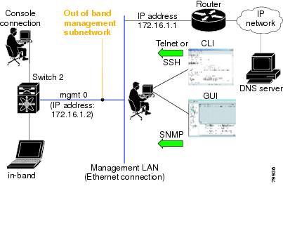
In-band options are compliant with and use the RFC 2625 standards. An NMS host running the IP protocol over an Fibre Channel interface can access the switch using the IPFC functionality. If the NMS does not have a Fibre Channel HBA, in-band management can still be performed using one of the switches as an access point to the fabric as shown in Figure 5-1.
Figure 5-1 Management Access to Switches
Management Interface Configuration
The management interface on the switch allows multiple simultaneous Telnet or SNMP sessions. You can remotely configure the switch through the management interface, but first you must configure IP version 4 (IPv4) parameters (IP address, subnet mask) or an IP version 6 (IPv6) address and prefix length so that the switch is reachable. For information on configuring IPv6 addresses, see Chapter 8 "Configuring IPv6 for Gigabit Ethernet Interfaces."
On director class switches, a single IP address is used to manage the switch. The active supervisor module's management (mgmt0) interface uses this IP address. The mgmt0 interface on the standby supervisor module remains in an inactive state and cannot be accessed until a switchover happens. After a switchover, the mgmt0 interface on the standby supervisor module becomes active and assumes the same IP address as the previously active supervisor module.
Note
Note
About the Default Gateway
You can configure a default gateway IPv4 address on your Cisco MDS 9000 Family switch.
The default gateway IPv4 address should be configured along with the IPv4 static routing attributes (IP default network, destination prefix, and destination mask, and next hop address). If you configure the static route IP forwarding and the default-network details, these IPv4 addresses will be used regardless of the default-gateway being enabled or disabled.
The default gateway IPv4 address should be configured along with the IPv4 static routing attributes (IP default network, destination prefix, and destination mask, and next hop address).
Tip
IPv4 Default Network Configuration
If you assign the IPv4 default network address, the switch considers routes to that network as the last resort. If the IPv4 default network address is not available, the switch uses the IPv4 default gateway address. For every network configured with the IPv4 default network address, the switch flags that route as a candidate default route, if the route is available.
Tip
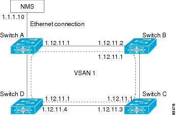
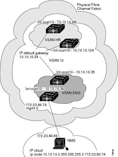
When the Ethernet interface is configured, the switch should point to the gateway router for the IP network. The host accesses the gateway using a gateway switch. This gateway switch is configured as the default gateway. The other switches in the fabric that are connected to the same VSAN as the gateway switch can also be connected through the gateway switch. Every interface connected to this VSAN should be configured with the VSAN IPv4 address of the gateway switch as shown in Figure 5-2.
Figure 5-2 Overlay VSAN Functionality
In Figure 5-1, switch A has the IPv4 address 1.12.11.1, switch B has the IPv4 address 1.12.11.2, switch C has the IPv4 address 1.12.11.3, and switch D has the IPv4 address 1.12.11.4. Switch A is the gateway switch with the Ethernet connection. The NMS uses the IPv4 address 1.1.1.10 to connect to the gateway switch. Frames forwarded to any switch in the overlaid VSAN 1 are routed through the gateway switch. Configuring the gateway switch's IPv4 address (1.12.11.1) in the other switches enable the gateway switch to forward the frame to the intended destination. Similarly, if a non-gateway switch in the VSAN forwards a frame to the Ethernet, the frame is routed through the gateway switch.
When forwarding is disabled (default), IP frames are not sent from one interface to another. In these cases, the software performs local IP routing between two switches using the in-band option for Fibre Channel traffic and the mgmt0 option for Ethernet traffic.
When a VSAN is created, a VSAN interface is not created automatically. You need to specifically create the interface.
IPFC
IPFC provides IP forwarding on in-band switch management over a Fibre Channel interface (rather than out-of-band using the Gigabit Ethernet mgmt 0 interface). You can be use IPFC to specify that IP frames can be transported over Fibre Channel using encapsulation techniques. IP frames are encapsulated into Fibre Channel frames so NMS information can cross the Fibre Channel network without using an overlay Ethernet network.
Once the VSAN interface is created, you can specify the IP address for that VSAN. You can assign an IPv4 address or an IPv6 address.
Note
About IPv4 Static Routes
Static routing is a mechanism to configure IPv4 routes on the switch. You can configure more than one static route.
If a VSAN has multiple exit points, configure static routes to direct traffic to the appropriate gateway switch. IPv4 routing is disabled by default on any gateway switch between the out-of-band management interface and the default VSAN, or between directly connected VSANs.
If your network configuration does not need an external router, you can configure IPv4 static routing on your MDS switch.
Note
About Overlay VSANs
VSANs enable deployment of larger SANs by overlaying multiple logical SANs, each running its own instance of fabric services, on a single large physical network. This partitioning of fabric services reduces network instability by containing fabric reconfiguration and error conditions within an individual VSAN. VSANs also provide the same isolation between individual VSANs as physically separated SANs. Traffic cannot cross VSAN boundaries and devices may not reside in more than one VSAN. Because each VSAN runs separate instances of fabric services, each VSAN has its own zone server and can be zoned in exactly the same way as SANs without VSAN capability.
About VRRP
Cisco MDS 9000 Family switches are compliant with RFC 2338 standards for Virtual Router Redundancy Protocol (VRRP) features. VRRP provides a redundant alternative path to the gateway switch, which has connectivity to the NMS. VRRP has the following features:
•
•
•
•
•
•
•
•
Note
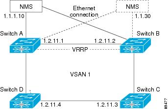
In Figure 5-3, switch A is the VRRP master and switch B is the VRRP backup switch. Both switches have an IP address to VRRP mapping configured. The other switches set switch A as the default gateway. If switch A fails, the other switches do not have to change the routing configurations as switch B automatically becomes the master and takes over the function of a gateway.
Figure 5-3 VRRP Functionality
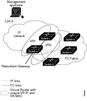
In Figure 5-4, the fabric example has two virtual router groups (VR1 and VR 2) because a virtual router cannot span across different types of interfaces. In both switch 1 and switch 2, the Ethernet interface is in VR 1 and the FC interface is in VR 2. Each virtual router is uniquely identified by the VSAN interface and the VR ID.
Figure 5-4 Redundant Gateway
DNS Server Configuration
The DNS client on the switch communicates with the DNS server to perform the IP address-name server correspondence.
The DNS server may be dropped after two attempts because of one of the following reasons:
•
•
Note
Guidelines and Limitations
Follow these guidelines to configure IPFC:
1.
2.
3.
4.
Default Settings
Table 5-1 lists the default settings for DNS features.
Table 5-1 Default DNS Settings
Domain lookup
Disabled
Domain name
Disabled
Domains
None
Domain server
None
Maximum domain servers
6
Table 5-2 lists the default settings for VRRP features.
Configuring IP Services
This section includes the following topics:
•
•
Configuring Management Interface
Detailed Steps
To configure the mgmt0 Ethernet interface using Device Manager for IPv6, follow these steps:
Step 1
Step 2
Step 3
Step 4
Step 5
Step 6
Configuring the Default Gateway
Detailed Steps
To configure an IP route, follow these steps:
Step 1
Step 2
You see the IP route window showing the switch name, destination, mask, gateway, metric, interface, and active status of each IP route.
Step 3
Step 4
•
•
•
•
Note
Step 5
To configure an IP route or identify the default gateway using Device Manager, follow these steps:
Step 1
You see the IP Routes window.
Step 2
Step 3
•
•
•
•
Note
If you choose the CPP interface, the switch uses the input CPP-assigned IP address and mask to generate the IP route prefix.
Step 4
Note
ip: route type not supported.
Configuring Overlay VSANs
Detailed Steps
To configure an overlay VSAN, follow these steps:
Step 1
Step 2
Step 3
Step 4
Figure 5-5 Overlay VSAN Configuration Example
Note
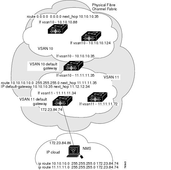
Configuring Multiple VSANs
More than one VSAN can be used to segment the management network in multiple subnets. An active interface must be present on the switch for the VSAN interface to be enabled.
Detailed Steps
To configure multiple VSANs, follow these steps:
Step 1
Step 2
Step 3
Step 4
Figure 5-6 Multiple VSAN Configuration Example
Configuring VRRP
This section describes how to configure VRRP and includes the following topics:
•
•
•
Adding Virtual Router IP Addresses
One virtual router IP address can be configured for a virtual router. If the configured IP address is the same as the interface IP address, this switch automatically owns the IP address. You can configure either an IPv4 address or an IPv6 address.
According to the VRRP specification, the master VRRP router drops the packets addressed to the virtual router's IP address because the virtual router is only intended as a next-hop router to forward packets. In MDS switches however, some applications require that packets addressed to virtual router's IP address be accepted and delivered to them. By using the secondary option to the virtual router IPv4 address, the VRRP router will accept these packets when it is the master.
Detailed Steps
To manage IP addresses for virtual routers from Device Manager, follow these steps:
Step 1
Step 2
Step 3
Step 4
Setting Virtual Router Authentication
VRRP security provides three options, including simple text authentication, MD5 authentication, and no authentication.
•
•
•
You can configure the key using the authentication option in the VRRP submode and distribute it using the configuration file. The security parameter index (SPI) settings assigned in this option should be unique for each VSAN.
Note
Note
Tracking the Interface Priority
Interface state tracking changes the priority of the virtual router based on the state of another interface in the switch. When the tracked interface is down, the priority reverts to the priority value for the virtual router (see the "Setting Virtual Router Authentication" section). When the tracked interface is up, the priority of the virtual router is restored to the interface state tracking value. You can track the state of either a specified VSAN interface or the management interface (mgmt 0). The interface state tracking feature is disabled by default.
Note
Field Descriptions for IP Services
This section describes the field descriptions.
IP Routes
IP Statistics ICMP
IP Statistics IP
IP Statistics SNMP
IP Statistics UDP
mgmt0 Statistics
TCP UDP TCP
TCP UDP UDP
VRRP General
VRRP IP Addresses
Interface, VRRP ID, IP Address
Interface, Virtual Router Redundancy Protocol ID, and associated IP address.
VRRP Statistics
CDP General
CDP Neighbors
Additional References
For additional information related to implementing IP storage, see the following section:
•
•
Related Document
Cisco MDS 9000 Family Command Reference
Cisco MDS 9000 Family Command Reference, Release 5.0(1a)
Standards
No new or modified standards are supported by this feature, and support for existing standards has not been modified by this feature.
-
RFCs
No new or modified RFCs are supported by this feature, and support for existing RFCs has not been modified.
-
MIBs