Feedback
Table Of Contents
Classifying the Switch to IOA Site
Displaying IOA Interface Status
Adding Nodes to an IOA Cluster
Adding Interfaces to an IOA Cluster
Adding N Ports to an IOA Cluster
Prerequisites for IOA Flow Setup Wizard
Using the IOA Flow Setup Wizard
Creating Multiple IOA Clusters on a Single Switch
Guidelines for Configuring IOA with NPV
Configuring NPIV on an NPV Core Switch, NPV on an NPV Device, and Activating NP Link
Configuring NPIV on the NPV Core Switch
Configuring NPV on the NPV Device, Bringing Up the NP Port and NP Uplink
Verifying the NPV Configuration
Creating and Activating an IOA Cluster
Enabling NPIV on the NPV Core Switches
Verifying the Configured NP Uplinks
Classifying the Switches into IOA Sites
Configuring Nodes to the IOA Cluster
Verifying the IOA Cluster Configuration
Configuring Interfaces in the IOA Cluster
Verifying the Cluster Interface Configuration
Adding N-Ports to the IOA cluster
Verifying the Configured N-Ports in the IOA Cluster
Configuring IOA Flows in the Cluster
Verifying the Configured IOA Flow
Displaying Interface Statistics
Additional Configurations for the Features Supported by NPV on IOA
Verifying the Configured Trunking NP Uplink Port on the NPV Core Switch
Verifying the Configured Trunking NP Uplink Port on NPV Device Switch
Configuring F-PortChannel on the NPV Core Switch
Verifying the Configured PortChannel of NP Links
Example for Configuring TF-TNP PortChannel Links
Configuring the PortChannel on the NPV Core Switch
Configuring PortChannel on the NPV Device Switch
Verifying the Configured PortChannel of TF-TNP Links
Configuring FlexAttach Virtual pWWN on an NPV Switch
Automatically Enabling FlexAttach Virtual pWWN
Manually Enabling FlexAttach Virtual pWWN
Verifying the Configured FlexAttach Virtual pWWN
Verifying the Configured FlexAttach Virtual pWWN
Configuring NPV Traffic Management on NPV Switches with IOA
Configuring a List of External Interfaces per Server Interface
Enabling or Disabling the Global Policy for Disruptive Load Balancing
Verifying the NPV Traffic Management on an NPV Switch
Example for Implementing IOA with NPV
Verifying the IOA Configuration
Setting the Tunable Parameters
Changing the Node Description and IP Address of an IOA Cluster
Changing the Node Description and IP Address of an IOA Cluster
Configuration Example for Changing the Node Description and Node IP Address of an IOA Cluster
Shut Down the IOA Cluster on switch1
Shut Down the IOA Cluster on switch2
Remove the IOA Cluster on switch2
Remove the Node of switch2 in switch1
Change the Management Interface IP Address on Switches
Change the Node Description and IP Address on switch1
Bring Up IOA Cluster on switch1
Add switch2 Node with New Description and the IP Address
Verify the Node Description and IP Address and Flows
Displaying Interface Statistics
Configuring IOA Using the CLI
This chapter describes how to configure IOA using the command line interface (CLI).
This chapter describes these sections:
•
Creating Multiple IOA Clusters on a Single Switch
Configuring IOA
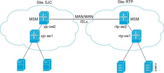
In this chapter, all configuration steps relate to a reference topology shown in Figure 4-1 where SJC and RTP represent two sites connected through the WAN or MAN ISLs. In this example, sjc-sw2 and rtp-sw2 represent the core switches where IOA is deployed. sjc-sw1 and rtp-sw1 are edge switches that has the hosts or targets connected to them.
Figure 4-1 IOA CLI Reference Topology
The process of configuring IOA involves a number of configuration tasks that should be completed in order.
On each IOA switch, complete the following configurations:
•
On the master IOA switch, complete the following configurations:
•
•
•
Enabling Clustering
The first step in the process of configuring IOA is to enable clustering in all of the IOA switches.
To enable or disable the IOA cluster on sjc-sw2, perform this task:
Step 1
sjc-sw2# conf t
sjc-sw2(config)#
Enters configuration mode.
Step 2
sjc-sw2(config)# feature cluster
Enables clustering.
sjc-sw2(config)# no feature cluster
Disables clustering.
To complete the configuration for the reference topology, enable clustering in rtp-sw2.
Enabling the IOA Service
After enabling the IOA cluster, the second step in the process of configuring IOA is to enable the IOA service on each of the IOA switches.
To enable the IOA service on sjc-sw2, perform this task:
Step 1
sjc-sw2# config t
Enters configuration mode.
Step 2
sjc-sw2(config)# feature ioa
Enables IOA feature.
sjc-sw2(config)# no feature ioa
Disables IOA feature.
To complete the configuration for the reference topology, enable the IOA service in rtp-sw2.
Classifying the Switch to IOA Site
Each of the IOA switches need to be classified into a site. Make sure that you classify only the IOA switches within the physical site into an IOA site.
To classify an IOA switch into the SJC site, perform this task:
To complete the configuration for the reference topology, classify rtp-sw2 into the RTP site.
Configuring IOA Interfaces
After enabling the cluster and enabling IOA, configure the IOA interfaces on the switch.
To provision an IOA interface, perform this task:
Note
To complete the configuration for the reference topology, configure the interfaces in rtp-sw2.
Displaying IOA Interface Status
After configuring the IOA interface, use the show int command to show whether the IOA interface is down. The interface is down until the interface is added to a cluster.
sjc-sw2# show interface ioa 2/1ioa2/1 is down (Not in any Cluster)0 device packets in, 0 device packets out0 device bytes in, 0 device bytes out0 peer packets in, 0 peer packets out0 peer bytes in, 0 peer bytes out0 i-t create request, 0 i-t create destroy0 i-t activate request, 0 i-t deactivate requestPossible reasons for the interface being down are as follows:
•
•
•
•
Configuring an IOA Cluster
To configure a cluster, start with a switch and create a cluster and add the remaining IOA switches into the cluster. From this point on, all cluster parameters can be configured from this switch.
To create an IOA cluster, perform this task:
Note
This section inlcudes the following topics:
•
•
•
•
Displaying IOA Cluster Status
The following examples display the cluster information:
Note
sjc-sw2# show ioa clusterIOA Cluster is tape_vaultCluster ID is 0x213a000dec3ee782Cluster status is onlineIs between sites SJC and RTPTotal Nodes are 2Cluster Infra Status : OperationalCluster is Administratively UpCluster Config Version : 26SSL for ICN : Not Configuredsjc-sw2# show ioa cluster tape_vaultIOA Cluster is tape_vaultCluster ID is 0x213a000dec3ee782Cluster status is onlineIs between sites SJC and RTPTotal Nodes are 2Cluster Infra Status : OperationalCluster is Administratively UpCluster Config Version : 26SSL for ICN : Not ConfiguredA cluster can have the following statuses:
•
•
•
The infrastructure status has the following values:
•
•
The administrative status has the following values:
•
•
Adding Nodes to an IOA Cluster
To add nodes to an IOA cluster, perform this task:
The following examples display the nodes information:
sjc-sw2# show ioa cluster summary-------------------------------------------------------------------------------Cluster Sites Status Master Switch-------------------------------------------------------------------------------tape_vault SJC, online 172.23.144.97RTPsjc-sw2# show ioa cluster tape_vault node summary-------------------------------------------------------------------------------Switch Site Status Master-------------------------------------------------------------------------------172.23.144.97(L) SJC online yes172.23.144.98 RTP online nosjc-sw2# show ioa cluster tape_vault nodeNode 172.23.144.97 is local switchNode ID is 1Status is onlineBelongs to Site SJCNode is the master switchNode 172.23.144.98 is remote switchNode ID is 2Status is onlineBelongs to Site RTPNode is not master switchAdding Interfaces to an IOA Cluster
To add IOA interfaces to an IOA cluster, perform this task:
The following examples display IOA interfaces information:sjc-sw2# show interface ioa2/1ioa2/1 is upMember of cluster tape_vault0 device packets in, 0 device packets out0 device bytes in, 0 device bytes out0 peer packets in, 0 peer packets out0 peer bytes in, 0 peer bytes out303 i-t create request, 300 i-t create destroy300 i-t activate request, 0 i-t deactivate requestsjc-sw2# show ioa cluster tape_vault interface summary-------------------------------------------------------------------------------Switch Interface Status Flows-------------------------------------------------------------------------------172.23.144.97(L) ioa2/1 up --172.23.144.97(L) ioa2/2 up --172.23.144.98 ioa2/1 up --172.23.144.98 ioa2/2 up --sjc-sw2# show ioa cluster tape_vault interfaceInterface ioa2/1 belongs to 172.23.144.97(L)(M)Status is upInterface ioa2/2 belongs to 172.23.144.97(L)(M)Status is upInterface ioa2/1 belongs to 172.23.144.98Status is upInterface ioa2/2 belongs to 172.23.144.98Status is up
Note
(M) indicates the Master switch.
Adding N Ports to an IOA Cluster
To add N ports to the IOA cluster, perform this task:::
This example shows how to display N ports configuration:
sjc-sw2# show ioa cluster tape_vault nports-------------------------------------------------------------------------------P-WWN Site Vsan-------------------------------------------------------------------------------10:00:00:00:00:00:00:01 SJC 10011:00:00:00:00:00:00:01 RTP 10010:00:00:00:00:00:00:02 SJC 10011:00:00:00:00:00:00:02 RTP 100Configuring the IOA Flows
Before configuring the IOA flows, flow groups must be created.
To create a new IOA flow group and add flows, perform this task::
Note
The following examples display the configured flow information:
sjc-sw2# show ioa cluster tape_vault flows-------------------------------------------------------------------------------Host WWN, VSAN WA TA Comp Status Switch,InterfaceTarget WWN Pair-------------------------------------------------------------------------------10:00:00:00:00:00:00:01, 100 Y Y N online 172.23.144.97, ioa2/111:00:00:00:00:00:00:01 172.23.144.98, ioa2/110:00:00:00:00:00:00:02, 100 Y Y Y online 172.23.144.97, ioa2/211:00:00:00:00:00:00:02 172.23.144.98, ioa2/2sjc-sw2# show ioa cluster tape_vault flows detailHost 10:00:00:00:00:00:00:01, Target 11:00:00:00:00:00:00:01, VSAN 100Is onlineBelongs to flowgroup tsmIs enabled for WA, TAIs assigned toSwitch 172.23.144.97 Interface ioa2/1 (Host Site)Switch 172.23.144.98 Interface ioa2/1 (Target Site)Host 10:00:00:00:00:00:00:02, Target 11:00:00:00:00:00:00:02, VSAN 100Is onlineBelongs to flowgroup tsmIs enabled for WA, TA, CompressionIs assigned toSwitch 172.23.144.97 Interface ioa2/2 (Host Site)Switch 172.23.144.98 Interface ioa2/2 (Target Site)IOA Flow Setup Wizard
You can use the IOA Flow Setup Wizard to simplify the provisioning of flows especially when there are many flows to provision, and when you add, remove, or replace host HBAs, tape drives or storage controllers.
This section includes the following topics:
•
•
Prerequisites for IOA Flow Setup Wizard
The following prerequisites must be met before you can invoke the IOA Flow Setup Wizard:
•
•
Using the IOA Flow Setup Wizard
To configure flows using the Flow Setup Wizard, follow these steps:
Step 1
sjc-sw1# ioa flow-setup cluster tape_vault flowgroup repln-fg vsan 100In the case of an IVR deployment, you can enter the following CLI command on an IVR border switch where IOA is deployed:
sjc-sw1# ioa ivr flow-setup cluster tape_vault flowgroup repln-fgThe wizard processes the active zone set for the VSAN and creates a set of candidate flows. When you use the ivr flow-setup command, the active IVR zone set is considered. The zone set may have local flows as well as flows that traverse across sites. The IOA Flow Setup Wizard runs through a series of steps as listed in this procedure to prune the list to capture only the flows that traverse across the sites that need to be accelerated.
Step 2
This step is only for those switches where none of the hosts or targets have been configured yet for acceleration. From the flows in the active zone set, a candidate switch list is prepared based on where the hosts and targets are logged into.
The following switches need to be classified into appropriate sites-------------------------------------------------------------------------------Do you want to classify sjc-sw1 into site sjc or rtp [sjc]Do you want to classify 172.23.144.96 into site sjc or rtp [sjc] rtpThe candidate flow list is now pruned to contain only the inter-site flows that need to be accelerated.
Step 3
The following nport to site mapping needs to be configured-------------------------------------------------------------------------------N-Port PWWN: 10:00:00:00:00:00:00:00 Site: sjcN-Port PWWN: 10:00:00:00:00:00:01:00 Site: sjcN-Port PWWN: 10:00:00:00:00:00:02:00 Site: sjcN-Port PWWN: 10:00:00:00:00:00:03:00 Site: sjcN-Port PWWN: 10:00:00:00:00:00:04:00 Site: sjcN-Port PWWN: 11:00:00:00:00:00:00:00 Site: rtpN-Port PWWN: 11:00:00:00:00:00:01:00 Site: rtpN-Port PWWN: 11:00:00:00:00:00:02:00 Site: rtpN-Port PWWN: 11:00:00:00:00:00:03:00 Site: rtpN-Port PWWN: 11:00:00:00:00:00:04:00 Site: rtpDo you want to configure the n-port to site mappings? (yes/no) [yes] yesStep 4
Replication traffic can flow in either direction.
Certain N-ports in this VSAN can act as both initiator and targetsIs the traffic flow primarily from sjc to rtp? (yes/no) [yes] yes
Step 5
The following flows will be configured-------------------------------------------------------------------------------Host: 10:00:00:00:00:00:00:00 VSAN: 100 Target: 11:00:00:00:00:00:00:00 VSAN:100Host: 10:00:00:00:00:00:00:00 VSAN: 100 Target: 11:00:00:00:00:00:01:00 VSAN:100Host: 10:00:00:00:00:00:00:00 VSAN: 100 Target: 11:00:00:00:00:00:02:00 VSAN:100Host: 10:00:00:00:00:00:00:00 VSAN: 100 Target: 11:00:00:00:00:00:03:00 VSAN:100Host: 10:00:00:00:00:00:01:00 VSAN: 100 Target: 11:00:00:00:00:00:00:00 VSAN:100Host: 10:00:00:00:00:00:01:00 VSAN: 100 Target: 11:00:00:00:00:00:01:00 VSAN:100Host: 10:00:00:00:00:00:01:00 VSAN: 100 Target: 11:00:00:00:00:00:02:00 VSAN:100Host: 10:00:00:00:00:00:01:00 VSAN: 100 Target: 11:00:00:00:00:00:03:00 VSAN:100Host: 10:00:00:00:00:00:02:00 VSAN: 100 Target: 11:00:00:00:00:00:00:00 VSAN:100Host: 10:00:00:00:00:00:02:00 VSAN: 100 Target: 11:00:00:00:00:00:01:00 VSAN:100Host: 10:00:00:00:00:00:02:00 VSAN: 100 Target: 11:00:00:00:00:00:02:00 VSAN:100Host: 10:00:00:00:00:00:02:00 VSAN: 100 Target: 11:00:00:00:00:00:03:00 VSAN:100Host: 10:00:00:00:00:00:03:00 VSAN: 100 Target: 11:00:00:00:00:00:00:00 VSAN:100Host: 10:00:00:00:00:00:03:00 VSAN: 100 Target: 11:00:00:00:00:00:01:00 VSAN:100Host: 10:00:00:00:00:00:03:00 VSAN: 100 Target: 11:00:00:00:00:00:02:00 VSAN:100Host: 10:00:00:00:00:00:03:00 VSAN: 100 Target: 11:00:00:00:00:00:03:00 VSAN:100Host: 10:00:00:00:00:00:04:00 VSAN: 100 Target: 11:00:00:00:00:00:04:00 VSAN:100Do you want to configure these flows? (yes/no) [yes] yesYou can display the configured flow information by using the following commands:
sjc-sw1# show ioa cluster tape_vault nports-------------------------------------------------------------------------------P-WWN Site Vsan-------------------------------------------------------------------------------10:00:00:00:00:00:00:00 sjc 10010:00:00:00:00:00:01:00 sjc 10010:00:00:00:00:00:02:00 sjc 10010:00:00:00:00:00:03:00 sjc 10010:00:00:00:00:00:04:00 sjc 10011:00:00:00:00:00:00:00 rtp 10011:00:00:00:00:00:01:00 rtp 10011:00:00:00:00:00:02:00 rtp 10011:00:00:00:00:00:03:00 rtp 10011:00:00:00:00:00:04:00 rtp 100sjc-sw1# show ioa cluster tape_vault flows-------------------------------------------------------------------------------Host WWN, VSAN WA TA Comp Status Switch,InterfaceTarget WWN Pair-------------------------------------------------------------------------------10:00:00:00:00:00:00:00, 100 Y N N offline --, --11:00:00:00:00:00:00:00 --, --10:00:00:00:00:00:01:00, 100 Y N N offline --, --11:00:00:00:00:00:00:00 --, --10:00:00:00:00:00:02:00, 100 Y N N offline --, --11:00:00:00:00:00:00:00 --, --10:00:00:00:00:00:03:00, 100 Y N N offline --, --11:00:00:00:00:00:00:00 --, --10:00:00:00:00:00:00:00, 100 Y N N offline --, --11:00:00:00:00:00:01:00 --, --10:00:00:00:00:00:01:00, 100 Y N N offline --, --11:00:00:00:00:00:01:00 --, --10:00:00:00:00:00:02:00, 100 Y N N offline --, --11:00:00:00:00:00:01:00 --, --10:00:00:00:00:00:03:00, 100 Y N N offline --, --11:00:00:00:00:00:01:00 --, --10:00:00:00:00:00:00:00, 100 Y N N offline --, --11:00:00:00:00:00:02:00 --, --10:00:00:00:00:00:01:00, 100 Y N N offline --, --11:00:00:00:00:00:02:00 --, --10:00:00:00:00:00:02:00, 100 Y N N offline --, --11:00:00:00:00:00:02:00 --, --10:00:00:00:00:00:03:00, 100 Y N N offline --, --11:00:00:00:00:00:02:00 --, --10:00:00:00:00:00:00:00, 100 Y N N offline --, --11:00:00:00:00:00:03:00 --, --10:00:00:00:00:00:01:00, 100 Y N N offline --, --11:00:00:00:00:00:03:00 --, --10:00:00:00:00:00:02:00, 100 Y N N offline --, --11:00:00:00:00:00:03:00 --, --10:00:00:00:00:00:03:00, 100 Y N N offline --, --11:00:00:00:00:00:03:00 --, --10:00:00:00:00:00:04:00, 100 Y N N offline --, --11:00:00:00:00:00:04:00 --, --If data is currently being transmitted through the flow, it is considered to be online and active. A throughput number in megabytes per second is shown for each flow that is online and active. Use the following commands to display all flows assigned to a single interface, or to display all flows assigned to all interfaces:
switch# show ioa online flows interface ioa2/1-------------------------------------------------------------------------------A Oc nt li iv nFLOW ID FLOW HOST FLOW TARGET VSAN e e MBps-------------------------------------------------------------------------------0 10:00:00:00:00:00:00:10 11:00:00:00:00:00:00:10 1 N Y 0.0017 42:00:00:00:00:00:00:11 41:00:00:00:00:00:00:11 1 N Y 0.0018 42:00:00:00:00:00:00:12 41:00:00:00:00:00:00:12 1 N Y 0.00--More--switch# show ioa online flows interface all-------------------------------------------------------------------------------A Oc nt li iv nFLOW ID FLOW HOST FLOW TARGET VSAN e e MBps-------------------------------------------------------------------------------0 10:00:00:00:00:00:00:10 11:00:00:00:00:00:00:10 1 N Y 0.0017 42:00:00:00:00:00:00:11 41:00:00:00:00:00:00:11 1 N Y 0.0018 42:00:00:00:00:00:00:12 41:00:00:00:00:00:00:12 1 N Y 0.0019 42:00:00:00:00:00:00:13 41:00:00:00:00:00:00:13 1 N Y 0.0020 42:00:00:00:00:00:00:14 41:00:00:00:00:00:00:14 1 N Y 0.0021 42:00:00:00:00:00:00:15 41:00:00:00:00:00:00:15 1 N Y 0.0022 42:00:00:00:00:00:00:16 41:00:00:00:00:00:00:16 1 N Y 0.0023 42:00:00:00:00:00:00:17 41:00:00:00:00:00:00:17 1 N Y 0.0024 42:00:00:00:00:00:00:18 41:00:00:00:00:00:00:18 1 N Y 0.0025 42:00:00:00:00:00:00:19 41:00:00:00:00:00:00:19 1 N Y 0.0026 42:00:00:00:00:00:00:1a 41:00:00:00:00:00:00:1a 1 N Y 0.0027 42:00:00:00:00:00:00:1b 41:00:00:00:00:00:00:1b 1 N Y 0.0028 42:00:00:00:00:00:00:1c 41:00:00:00:00:00:00:1c 1 N Y 0.0029 42:00:00:00:00:00:00:1d 41:00:00:00:00:00:00:1d 1 N Y 0.0030 42:00:00:00:00:00:00:1e 41:00:00:00:00:00:00:1e 1 N Y 0.0031 42:00:00:00:00:00:00:1f 41:00:00:00:00:00:00:1f 1 N Y 0.0032 42:00:00:00:00:00:00:20 41:00:00:00:00:00:00:20 1 N Y 0.0033 42:00:00:00:00:00:00:21 41:00:00:00:00:00:00:21 1 N Y 0.0034 42:00:00:00:00:00:00:22 41:00:00:00:00:00:00:22 1 N Y 0.0035 42:00:00:00:00:00:00:23 41:00:00:00:00:00:00:23 1 N Y 0.0036 42:00:00:00:00:00:00:24 41:00:00:00:00:00:00:24 1 N Y 0.0037 42:00:00:00:00:00:00:25 41:00:00:00:00:00:00:25 1 N Y 0.0038 42:00:00:00:00:00:00:26 41:00:00:00:00:00:00:26 1 N Y 0.0039 42:00:00:00:00:00:00:27 41:00:00:00:00:00:00:27 1 N Y 0.0040 42:00:00:00:00:00:00:28 41:00:00:00:00:00:00:28 1 N Y 0.0041 42:00:00:00:00:00:00:29 41:00:00:00:00:00:00:29 1 N Y 0.0042 42:00:00:00:00:00:00:2a 41:00:00:00:00:00:00:2a 1 N Y 0.0043 42:00:00:00:00:00:00:2b 41:00:00:00:00:00:00:2b 1 N Y 0.0044 42:00:00:00:00:00:00:2c 41:00:00:00:00:00:00:2c 1 N Y 0.0045 42:00:00:00:00:00:00:2d 41:00:00:00:00:00:00:2d 1 N Y 0.0046 42:00:00:00:00:00:00:2e 41:00:00:00:00:00:00:2e 1 N Y 0.0047 42:00:00:00:00:00:00:2f 41:00:00:00:00:00:00:2f 1 N Y 0.0048 42:00:00:00:00:00:00:30 41:00:00:00:00:00:00:30 1 N Y 0.0049 42:00:00:00:00:00:00:31 41:00:00:00:00:00:00:31 1 N Y 0.00switch#Creating Multiple IOA Clusters on a Single Switch
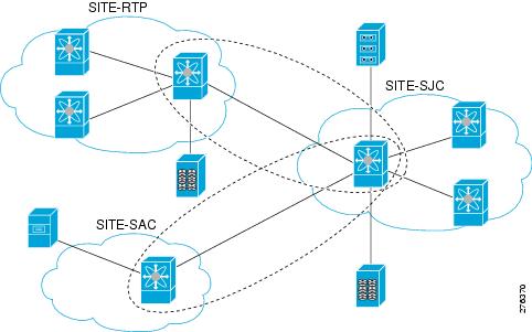
Figure 4-2 illustrates the IOA implementation where the IOA service is extended across multiple sites. In the illustration, Site-SJC consolidates the tape backup from Site-RTP and Site-SAC. Each IOA cluster represents a site pair, which means there are two unique clusters. This topology provides segregation and scalability of the IOA service across multiple sites. In the Site-SJC, a single switch can participate in multiple IOA clusters.
Figure 4-2 Extended Across Multiple Sites
Note
To create another IOA cluster on sjc-sw2 with SAC, follow these steps:
The following example displays the multiple clusters created using the SJC site:
sjc-sw2# show ioa cluster summary-------------------------------------------------------------------------------Cluster Sites Status Master Switch-------------------------------------------------------------------------------tape_vault SJC, online 172.25.231.19RTPtape_vault_site2 SAC, online 172.25.231.19SJC
Note
Note
Configuring IOA with NPV
You can use the Cisco MDS 9000 Family I/O Accelerator (IOA) with N port virtualization (NPV) to reduce the number of Fibre Channel domain IDs in SANs. Switches operating in NPV mode does not join a fabric or exchange traffic between NPV core switch links and end devices. You can deploy multiple edge switches without any shortage of domain IDs. NPV is not available in switch mode. To make NPV available on a switch, you must turn on NPV mode.
You can use the Cisco MDS 9000 Family I/O Accelerator (IOA) with N port ID virtualization (NPIV). NPIV efficiently utilizes the HBA ports on the blade servers in a data center and reduces the number of FCIDs assigned to the HBA ports.
The switches are not in NPV mode by default. NPV is supported in the following Cisco MDS 9000 switches:
•
•
•
•
Note
Guidelines for Configuring IOA with NPV
Follow these guidelines to configure IOA with NPV:
•
•
Note
•
•
•
•
•
•
•
•
•
•
•
•
Configuring NPIV on an NPV Core Switch, NPV on an NPV Device, and Activating NP Link
The following procedures are used to enable NPV and NPIV:
•
•
•
•
•
•
•
Configuring NPIV on the NPV Core Switch
To enable NPIV and NPV, perform this task:
Configuring NPV on the NPV Device, Bringing Up the NP Port and NP Uplink
To configure NPV on an NPV device, perform this task:
Verifying the NPV Configuration
To view all the NPV devices in all the VSANs on the NPV core switch, enter the show fcns database command.
switch# show fcns databaseVSAN 1:--------------------------------------------------------------------------FCID TYPE PWWN (VENDOR) FC4-TYPE:FEATURE--------------------------------------------------------------------------0x010000 N 20:01:00:0d:ec:2f:c1:40 (Cisco) npv0x010001 N 20:02:00:0d:ec:2f:c1:40 (Cisco) npv0x010200 N 21:00:00:e0:8b:83:01:a1 (Qlogic) scsi-fcp:init0x010300 N 21:01:00:e0:8b:32:1a:8b (Qlogic) scsi-fcp:initTotal number of entries = 4To display a list of the NPV devices that are logged in, along with VSANs, source information, pWWNs, and FCIDs, on the NPV device, enter the show npv flogi-table command.
switch# show npv flogi-table--------------------------------------------------------------------------------SERVER EXTERNALINTERFACE VSAN FCID PORT NAME NODE NAME INTERFACE--------------------------------------------------------------------------------fc1/19 1 0xee0008 10:00:00:00:c9:60:e4:9a 20:00:00:00:c9:60:e4:9a fc1/9fc1/19 1 0xee0009 20:00:00:00:0a:00:00:01 20:00:00:00:c9:60:e4:9a fc1/1fc1/19 1 0xee000a 20:00:00:00:0a:00:00:02 20:00:00:00:c9:60:e4:9a fc1/9fc1/19 1 0xee000b 33:33:33:33:33:33:33:33 20:00:00:00:c9:60:e4:9a fc1/1Total number of flogi = 4.To display the status of the different servers and external interfaces, on the NPV device, enter the show npv status command.
switch# show npv statusnpiv is enabledExternal Interfaces:====================Interface: fc1/1, VSAN: 2, FCID: 0x1c0000, State: UpInterface: fc1/2, VSAN: 3, FCID: 0x040000, State: UpNumber of External Interfaces: 2Server Interfaces:==================Interface: fc1/7, VSAN: 2, NPIV: No, State: UpInterface: fc1/8, VSAN: 3, NPIV: No, State: UpNumber of Server Interfaces: 2Creating and Activating an IOA Cluster
Note
Note
Configuring NPV on IOA
This section describes the following configuration procedures used to configure NPV on IOA:
•
•
•
•
•
•
•
•
•
•
•
•
•
Enabling NPV
To enable NPV, perform this task:
Enabling NPIV on the NPV Core Switches
To enable NPIV on the NPV core switches, perform this task:
Verifying the Configured NP Uplinks
Use the following show commands to confirm the functioning of the configured NP uplinks on the NPV device sjc-sw1:
sjc-sw1# show npv statusnpiv is enabledExternal Interfaces:====================Interface: fc1/6, VSAN: 500, FCID: 0xaf0000, State: UpNumber of External Interfaces: 1Server Interfaces:==================Interface: fc1/7, VSAN: 500, State: UpInterface: fc1/8, VSAN: 500, State: UpNumber of Server Interfaces: 2sjc-sw1# show interface fc 1/6fc1/6 is upHardware is Fibre Channel, SFP is short wave laser w/o OFC (SN)Port WWN is 20:06:00:0d:ec:3d:92:00Admin port mode is NP, trunk mode is offsnmp link state traps are enabledPort mode is NPPort vsan is 500Speed is 2 GbpsRate mode is dedicatedTransmit B2B Credit is 16Receive B2B Credit is 16Receive data field Size is 2112Beacon is turned off5 minutes input rate 1956320 bits/sec, 244540 bytes/sec, 3617 frames/sec5 minutes output rate 132841568 bits/sec, 16605196 bytes/sec, 11309 frames/sec6219674043 frames input, 349356203708 bytes0 discards, 0 errors0 CRC, 0 unknown class0 too long, 0 too short36666335463 frames output, 64666483082476 bytes512 discards, 0 errors36 input OLS, 23 LRR, 2 NOS, 0 loop inits29 output OLS, 17 LRR, 14 NOS, 0 loop inits0 receive B2B credit remaining16 transmit B2B credit remaining14 low priority transmit B2B credit remainingInterface last changed at Mon Oct 10 10:07:54 2011sjc-sw1# sh npv flogi-table--------------------------------------------------------------------------------SERVER EXTERNALINTERFACE VSAN FCID PORT NAME NODE NAME INTERFACE--------------------------------------------------------------------------------fc1/7 500 0xbe005a 10:00:02:c8:01:cc:01:21 10:00:00:00:11:86:00:00 fc1/6fc1/8 500 0xbe0214 10:00:02:c8:01:cc:01:81 10:00:00:00:11:86:00:00 fc1/6Total number of flogi = 1Use the following show commands to confirm the functioning of the configured NP uplinks on the NPV device sjc-sw2:
sjc-sw2# show npiv statusNPIV is enabledsjc-sw2# show int fc 1/5fc1/9 is upHardware is Fibre Channel, SFP is short wave laser w/o OFC (SN)Port WWN is 20:09:00:0d:ec:3d:92:00Admin port mode is F, trunk mode is offsnmp link state traps are enabledPort mode is F, FCID is 0xbe0044Port vsan is 500Speed is 2 GbpsRate mode is dedicatedTransmit B2B Credit is 16Receive B2B Credit is 16Receive data field Size is 2112Beacon is turned off5 minutes input rate 0 bits/sec, 0 bytes/sec, 0 frames/sec5 minutes output rate 8 bits/sec, 1 bytes/sec, 0 frames/sec4283 frames input, 231280 bytes0 discards, 0 errors0 CRC, 0 unknown class0 too long, 0 too short4348 frames output, 2295004 bytes0 discards, 0 errors1 input OLS, 1 LRR, 2 NOS, 0 loop inits1 output OLS, 1 LRR, 1 NOS, 0 loop inits16 receive B2B credit remaining16 transmit B2B credit remaining16 low priority transmit B2B credit remainingInterface last changed at Fri Sep 30 09:24:40 2011Enabling IOA on the IOA Nodes
To enable IOA on the first IOA node sjc-sw2 in site SJC, perform this task:
To enable IOA on the first IOA node rtp-sw2 in Site RTP, perform this task:
Classifying the Switches into IOA Sites
To configure the IOA site on sjc-sw2, perform this task:
Step 1
sjc-sw2# config t
Enters configuration mode.
Step 2
sjc-sw2(config)# ioa site-local SJC
Classifying the switches into IOA site.
To configure the IOA site on rtp-sw2, perform this task:
Step 1
rtp-sw2# config t
Enters configuration mode.
Step 2
rtp-sw2(config)# ioa site-local RTP
Classifying the switches into IOA site.
Configuring IOA Interfaces
To configure IOA interface on sjc-sw2, perform this task:
To configure IOA interface on rtp-sw2, perform this task:
Configuring IOA Cluster
To configure IOA cluster on sjc-sw2, perform this task:
Step 1
sjc-sw2# config t
Enters configuration mode.
Step 2
sjc-sw2(config)# ioa cluster DC1
Configures IOA cluster. cluster name are case sensitive.
Configuring Nodes to the IOA Cluster
To add an IOA cluster on sjc-sw2 , perform this task:
Verifying the IOA Cluster Configuration
Use the following show commands to confirm the functioning of the IOA cluster on sjc-sw2:
sjc-sw2# show ioa clusterIOA Cluster is DC1Cluster ID is 0x2003000573cbe602Cluster status is onlineIs between sites SJC and RTPTotal Nodes are 2Cluster Infra Status : OperationalCluster is Administratively UpCluster Config Version : 707SSL for ICN : Not Configuredsjc-sw2# show ioa cluster DC1 summary-------------------------------------------------------------------------------Cluster Sites Status Master Switch-------------------------------------------------------------------------------DC1 SJC, online 10.65.217.48RTPsjc-sw2# show ioa cluster DC1 nodeNode 10.65.217.48 is local switchNode ID is 1IP address is 10.65.217.48Status is onlineBelongs to Site SJCNode is the master switchNode 10.65.217.56 is remote switchNode ID is 2IP address is 10.65.217.56Status is onlineBelongs to Site RTPNode is not master switch
Note
Configuring Interfaces in the IOA Cluster
To add IOA interfaces to the IOA cluster on the Master switch sjc-sw2, perform this task:
Verifying the Cluster Interface Configuration
Use the following show commands to confirm the functioning configured cluster interface:
sjc-sw2# show interface ioa 1/1ioa1/1 is upMember of cluster DC121368133123 device packets in, 6851375618 device packets out31397026863066 device bytes in, 476831158620 device bytes out914301804 peer packets in, 8706253930 peer packets out56107433228 peer bytes in, 17877494274392 peer bytes out0 i-t create request, 0 i-t create destroy0 i-t activate request, 0 i-t deactivate requestsjc-sw2# show ioa cluster DC1 interface summary-------------------------------------------------------------------------------Switch Interface Status Flows-------------------------------------------------------------------------------10.65.217.48(L) ioa1/1 up --10.65.217.56 ioa1/1 up --
Note
Adding N-Ports to the IOA cluster
To add N Ports (hosts and targets) to the IOA cluster on the master switch sjc-sw2, perform this task:
Verifying the Configured N-Ports in the IOA Cluster
Use the following show command to confirm the functioning of the configured N-Ports in the IOA cluster:
sjc-sw2# show ioa cluster DC1 nports-------------------------------------------------------------------------------P-WWN Site Vsan-------------------------------------------------------------------------------10:00:02:c8:01:cc:01:01 SITE sjc 50010:00:02:c8:01:cc:02:01 SITE rtp 500
Note
Configuring IOA Flows in the Cluster
To configure IOA flows in the IOA cluster on the master switch sjc-sw2, perform this task:
Verifying the Configured IOA Flow
Use the following show commands to confirm the functioning of the IOA flow configuration and to verify status of the flow on the Master switch sjc-sw2 issue:
sjc-sw2# show ioa cluster DC1 flows flowgroup Dep1-------------------------------------------------------------------------------Host WWN, VSAN WA TA Comp Status Switch,InterfaceTarget WWN Pair-------------------------------------------------------------------------------10:00:02:c8:01:cc:01:01, 500 Y N N online 10.65.217.48, ioa1/110:00:02:c8:01:cc:02:01 500 10.65.217.56, ioa1/1sjc-sw2# show ioa cluster DC1 flows flowgroup Dep1 detailHost 10:00:02:c8:01:cc:01:01, VSAN 500, Target 10:00:02:c8:01:cc:02:01, VSAN 500Is onlineBelongs to flowgroup Dep1Is enabled for WA,Is assigned toSwitch 10.65.217.48 Interface ioa1/1 (Host Site)Switch 10.65.217.56 Interface ioa1/1 (Target Site)Displaying Interface Statistics
Use the following show commands to verify the IOA interface counters when live packets are ran over the IOA flow:
sjc-sw2# show interface ioa 1/1 countersioa1/121523240117 device packets in, 6901040984 device packets out31625069090806 device bytes in, 480287657508 device bytes out920937376 peer packets in, 8769431691 peer packets out56514685912 peer bytes in, 18007222544310 peer bytes out1 i-t create request, 0 i-t create destroy1 i-t activate request, 0 i-t deactivate requestsjc-sw2# show ioa internal interface ioa 1/1 summary---- ----------------------- ---- ------------- ---- ---FLOW HOST VSAN STATUS COMP ACCTARGET---- ----------------------- ---- ------------- ---- ---1 10:00:02:c8:01:cc:01:01 500 ACTIVE NO TA10:00:02:c8:01:cc:02:01Additional Configurations for the Features Supported by NPV on IOA
This section inlcudes the following topics:
•
•
•
The following features are supported by NPV on IOA:
•
•
•
•
NP Link Trunking
Configuring an NP Uplink Port
To configure an NP link, you must bring up the TF-TNP link between an F port in the NPIV core switch and then configure a NP port in the NPV switch.
To configure an NPV core switch, perform this task:
To configure an NPV device switch, perform this task:
Verifying the Configured Trunking NP Uplink Port on the NPV Core Switch
Use the following show commands to confirm the functioning configured NPV core switch:
sjc-sw2(config-if)# show int fc 1/2fc1/2 is trunkingHardware is Fibre Channel, SFP is short wave laser w/o OFC (SN)Port WWN is 20:04:00:05:73:cb:e6:00Admin port mode is auto, trunk mode is onsnmp link state traps are enabledPort mode is TFPort vsan is 9Speed is 4 GbpsRate mode is dedicatedTransmit B2B Credit is 16Receive B2B Credit is 16Receive data field Size is 2112Beacon is turned offBelongs to port-channel 21Trunk vsans (admin allowed and active) (9-13)Trunk vsans (up) (9,10)Trunk vsans (isolated) ()Trunk vsans (initializing) (11-13)5 minutes input rate 0 bits/sec, 0 bytes/sec, 0 frames/sec5 minutes output rate 8 bits/sec, 1 bytes/sec, 0 frames/sec231 frames input, 16680 bytes0 discards, 0 errors0 CRC, 0 unknown class0 too long, 0 too short248 frames output, 114660 bytes0 discards, 0 errors1 input OLS, 1 LRR, 1 NOS, 0 loop inits2 output OLS, 3 LRR, 0 NOS, 1 loop inits16 receive B2B credit remaining16 transmit B2B credit remaining14 low priority transmit B2B credit remainingVerifying the Configured Trunking NP Uplink Port on NPV Device Switch
Use the following show commands to confirm the functioning configured NPV device switch:
sjc-sw1(config-if)# show int fc 1/2fc1/2 is trunkingHardware is Fibre Channel, SFP is short wave laser w/o OFC (SN)Port WWN is 20:06:00:0d:ec:3d:92:00Admin port mode is NP, trunk mode is onsnmp link state traps are enabledPort mode is TNPPort vsan is 9Speed is 4 GbpsRate mode is dedicatedTransmit B2B Credit is 16Receive B2B Credit is 16Receive data field Size is 2112Beacon is turned offBelongs to port-channel 21Trunk vsans (admin allowed and active) (9-13)Trunk vsans (up) (9,10)Trunk vsans (isolated) ()Trunk vsans (initializing) (11-13)5 minutes input rate 0 bits/sec, 0 bytes/sec, 0 frames/sec5 minutes output rate 0 bits/sec, 0 bytes/sec, 0 frames/sec2837806124 frames input, 147817029296 bytes0 discards, 0 errors0 CRC, 0 unknown class0 too long, 0 too short26077437111 frames output, 49186719497132 bytes512 discards, 0 errors36 input OLS, 23 LRR, 2 NOS, 0 loop inits29 output OLS, 17 LRR, 14 NOS, 0 loop inits16 receive B2B credit remaining16 transmit B2B credit remaining14 low priority transmit B2B credit remainingInterface last changed at Mon Oct 10 10:07:54 2011
Note
Configuring F-PortChannel
To configure F-PortChannel (FPC) in shared mode and bring up the link between F ports on the NPIV core switches and NP ports on the NPV use the procedure in this section.
Note
Configuring F-PortChannel on the NPV Core Switch
To configure the F-PortChannel on an NPV core switch, perform this task:
To configure NP-PortChannel on an NPV device switch, perform this task:
To turn on the administrative state of all the PortChannel member interfaces in NPV core switch, perform this task:
To turn on the administrative state of all the PortChannel member interfaces in NPV device switch, perform this task:
Verifying the Configured PortChannel of NP Links
Use the following show commands to verify the configured PortChannel on the NPV core switch side:
sjc-sw2(config-if)# show interface port-channel 1port-channel 1 is upHardware is Fibre ChannelPort WWN is 24:15:00:05:73:cb:e6:00Admin port mode is NP, trunk mode is offsnmp link state traps are enabledPort mode is NPPort vsan is 500Speed is 8 GbpsTrunk vsans (admin allowed and active) (500-512)Trunk vsans (up) (500,512)Trunk vsans (isolated) ()Trunk vsans (initializing) (501-511)5 minutes input rate 0 bits/sec, 0 bytes/sec, 0 frames/sec5 minutes output rate 0 bits/sec, 0 bytes/sec, 0 frames/sec792 frames input, 51848 bytes0 discards, 0 errors0 CRC, 0 unknown class0 too long, 0 too short811 frames output, 417880 bytes0 discards, 0 errors2 input OLS, 2 LRR, 1 NOS, 0 loop inits3 output OLS, 4 LRR, 0 NOS, 2 loop initsMember[1] : fc2/1Member[2] : fc2/2Member[3] : fc2/3Interface last changed at Wed Oct 12 08:12:36 2011Use the following show commands to verify the configured PortChannel on the NPV device switch side:
switch# show interface port-channel 1port-channel 1 is trunkingHardware is Fibre ChannelPort WWN is 24:15:00:05:73:cb:e6:00Admin port mode is auto, trunk mode is offsnmp link state traps are enabledPort mode is NPPort vsan is 500Speed is 8 GbpsTrunk vsans (admin allowed and active) (500-512)Trunk vsans (up) (500,512)Trunk vsans (isolated) ()Trunk vsans (initializing) (501-511)5 minutes input rate 0 bits/sec, 0 bytes/sec, 0 frames/sec5 minutes output rate 0 bits/sec, 0 bytes/sec, 0 frames/sec792 frames input, 51848 bytes0 discards, 0 errors0 CRC, 0 unknown class0 too long, 0 too short811 frames output, 417880 bytes0 discards, 0 errors2 input OLS, 2 LRR, 1 NOS, 0 loop inits3 output OLS, 4 LRR, 0 NOS, 2 loop initsMember[1] : fc1/1Member[2] : fc1/2Member[3] : fc1/3Interface last changed at Wed Oct 12 08:12:36 2011Example for Configuring TF-TNP PortChannel Links
This example shows the following configuration procedures used to change the PortChannels in dedicated mode to bring up the TF-TNP PortChannel link between TF ports in the NPIV core switch, and TNP ports in the NPV switch.
Configuring the PortChannel on the NPV Core Switch
To configure the PortChannel on an NPV core switch, perform this task:
Configuring PortChannel on the NPV Device Switch
To configure PortChannel on an NPV device switch, perform this task:
To turn on the administrative state of all the PortChannel member interfaces in NPV core switch, perform this task:
To turn on the administrative state of all the PortChannel member interfaces in NPV device switch, perform this task:
Note
Verifying the Configured PortChannel of TF-TNP Links
Use the following show commands to verify the configured PortChannel on the NPV core switch side:
sjc-sw2# show interface port-channel 1port-channel 1 is trunkingHardware is Fibre ChannelPort WWN is 24:15:00:05:73:cb:e6:00Admin port mode is auto, trunk mode is onsnmp link state traps are enabledPort mode is TFPort vsan is 500Speed is 8 GbpsTrunk vsans (admin allowed and active) (500-512)Trunk vsans (up) (500,512)Trunk vsans (isolated) ()Trunk vsans (initializing) (501-511)5 minutes input rate 0 bits/sec, 0 bytes/sec, 0 frames/sec5 minutes output rate 0 bits/sec, 0 bytes/sec, 0 frames/sec792 frames input, 51848 bytes0 discards, 0 errors0 CRC, 0 unknown class0 too long, 0 too short811 frames output, 417880 bytes0 discards, 0 errors2 input OLS, 2 LRR, 1 NOS, 0 loop inits3 output OLS, 4 LRR, 0 NOS, 2 loop initsMember[1] : fc2/1Member[2] : fc2/2Member[3] : fc2/3Interface last changed at Wed Oct 12 08:22:36 2011Use the following show commands to verify the configured PortChannel on the NPV device switch side:
sjc-sw2# show interface port-channel 1port-channel 1 is trunkingHardware is Fibre ChannelPort WWN is 24:15:00:05:73:cb:e6:00Admin port mode is auto, trunk mode is onsnmp link state traps are enabledPort mode is TNPPort vsan is 500Speed is 8 GbpsTrunk vsans (admin allowed and active) (500-512)Trunk vsans (up) (500,512)Trunk vsans (isolated) ()Trunk vsans (initializing) (501-511)5 minutes input rate 0 bits/sec, 0 bytes/sec, 0 frames/sec5 minutes output rate 0 bits/sec, 0 bytes/sec, 0 frames/sec792 frames input, 51848 bytes0 discards, 0 errors0 CRC, 0 unknown class0 too long, 0 too short811 frames output, 417880 bytes0 discards, 0 errors2 input OLS, 2 LRR, 1 NOS, 0 loop inits3 output OLS, 4 LRR, 0 NOS, 2 loop initsMember[1] : fc1/1Member[2] : fc1/2Member[3] : fc1/3Interface last changed at Wed Oct 12 08:22:36 2011Configuring FlexAttach Virtual pWWN on an NPV Switch
The FlexAttach virtual pWWN feature facilitates server and configuration management. In a SAN environment, the server installation or replacement requires interaction and coordination among the SAN and server administrators. It is important that the SAN configuration does not change when a new server is installed, or when an existing server is replaced.
FlexAttach virtual pWWN minimizes the interaction between the server administrator and the SAN administrator by abstracting the real pWWN using virtual pWWNs. When FlexAttach virtual pWWN is enabled on an interface, a virtual pWWN is assigned to the server interface. The real pWWN is replaced by a virtual pWWN, which is used for a SAN configuration such as zoning.
With pWWNs configured on NPV switch in various forms as described in the next section, IOA works seamlessly with PwwNs. The pWWNs feature is enabled automatically, manually, or by mapping pWWN to virtual pWWN.
Automatically Enabling FlexAttach Virtual pWWN
The virtual pWWN is enabled automatically on all of the NPV switches or per port on the NPV device. When enabled automatically, a virtual WWN is generated from the device switch WWN. This WWN is used as the virtual pWWN. Virtual pWWNs are generated using the local switch WWNs.
Note
To enable virtual pWWN automatically, perform this task:
Manually Enabling FlexAttach Virtual pWWN
You can manually assign a WWN to the interface, without generating it through the switch. Several checks are done by the NPV core to ensure the uniqueness of virtual pWWNs in the switch. When duplicate virtual pWWNs are configured, the subsequent logins are rejected by the NPV core switch.
Note
•
•
To enable virtual pWWN manually, perform this task:
Verifying the Configured FlexAttach Virtual pWWN
Use the following show commands to verify the type and value of virtual pWWNs are correct:
sjc-sw1# show flex-attach virtual-wwnVIRTUAL PORT WWNS ASSIGNED TO INTERFACES----------------------------------------------------------------------VSAN INTERFACE VIRTUAL-PWWN AUTO LAST-CHANGE----------------------------------------------------------------------1 fc1/1 00:00:00:00:00:00:00:001 fc1/2 22:73:00:05:30:01:6e:1e TRUE Thu Jan 31 01:58:52 20081 fc1/3 22:5e:00:05:30:01:6e:1e TRUE Thu Jan 31 01:58:52 20081 fc1/4 22:5f:00:05:30:01:6e:1e TRUE Thu Jan 31 01:58:52 20081 fc1/5 22:74:00:05:30:01:6e:1e TRUE Thu Jan 31 01:26:24 20081 fc1/6 22:60:00:05:30:01:6e:1e TRUE Thu Jan 31 01:58:52 20081 fc1/7 22:61:00:05:30:01:6e:1e TRUE Thu Jan 31 01:58:52 20081 fc1/8 22:62:00:05:30:01:6e:1e TRUE Thu Jan 31 01:58:52 20081 fc1/9 22:63:00:05:30:01:6e:1e TRUE Thu Jan 31 01:58:52 20081 fc1/10 22:64:00:05:30:01:6e:1e TRUE Thu Jan 31 01:58:52 20081 fc1/11 22:65:00:05:30:01:6e:1e TRUE Thu Jan 31 01:58:52 20081 fc1/12 22:66:00:05:30:01:6e:1e TRUE Thu Jan 31 01:58:52 2008Verifying the Configured FlexAttach Virtual pWWN
Use the following show commands to verify that the end device is logged with the correct virtual WWNs:
switch# show fcns databaseVSAN 1:--------------------------------------------------------------------------FCID TYPE PWWN (VENDOR) FC4-TYPE:FEATURE--------------------------------------------------------------------------0x010000 N 20:01:00:0d:ec:2f:c1:40 (Cisco) npv0x010001 N 20:02:00:0d:ec:2f:c1:40 (Cisco) npv0x010200 N 21:00:00:e0:8b:83:01:a1 (Qlogic) scsi-fcp:init0x010300 N 21:01:00:e0:8b:32:1a:8b (Qlogic) scsi-fcp:initTotal number of entries = 4Configuring NPV Traffic Management on NPV Switches with IOA
Configuring NPV traffic management involves configuring a list of external interfaces to the servers, and enabling or disabling disruptive load balancing. The NPV traffic management feature is enabled after configuring NPV.
Configuring a List of External Interfaces per Server Interface
A list of external interfaces is linked to the server interfaces when the server interface is down, or if the specified external interface list includes the external interface already in use.
To configure the list of external interfaces per server interface, perform this task:
Note
Enabling or Disabling the Global Policy for Disruptive Load Balancing
Disruptive load balancing allows you to review the load on all the external interfaces and balance the load disruptively. Disruptive load balancing is done by moving the servers using heavily loaded external interfaces, to the external interfaces running with fewer loads.
To enable or disable the global policy for disruptive load balancing, perform this task:
Verifying the NPV Traffic Management on an NPV Switch
Use the following show command to display the NPV traffic map on an NPV switch:
switch# show npv traffic-mapNPV Traffic Map Information:----------------------------------------Server-If External-If(s)----------------------------------------fc1/3 fc1/10,fc1/11fc1/5 fc1/1,fc1/2----------------------------------------Use the following show command to display the NPV internal traffic details on an NPV switch:
switch# show npv internal info traffic-mapNPV Traffic Map Information:----------------------------------------Server-If External-If(s)----------------------------------------fc1/3 fc1/10,fc1/11fc1/5 fc1/1,fc1/2----------------------------------------Example for Implementing IOA with NPV
In this implementation example, an NPIV-capable server is the host directly connected to the NPV core (NPIV-enabled) switch which also acts as an IOA node. The host sends data to the target over IOA flows.
To enable NPIV on NPV core switch, perform this task:
Step 1
sjc-sw2# config t
Enters configuration mode.
Step 2
sjc-sw1(config)# feature npiv
Enables NPIV mode on a NPV core switch.
To enable IOA on all the IOA nodes and to bring up the IOA flows, perform this task:
Step 1
sjc-sw2# config t
Enters configuration mode.
Step 2
sjc-sw1(config)# feature npiv
Enables NPIV mode on a NPV nodes switches.
Verifying the IOA Configuration
Use the following show command to verify the IOA configuration:
sjc-sw1# show npiv statusNPIV is enabledAdditional Configurations
This section inlcudes the following topics:
•
•
Shutting Down a Cluster
To shut down a cluster, perform this task:
Step 1
sjc-sw2# config t
Enters configuration mode.
Step 2
sjc-sw2(config)# ioa cluster tape_vault
Specifies the cluster name and enters IOA cluster configuration submode. A cluster name can include a maximum of 31 alphabetical characters.
Step 3
sjc-sw2(config-ioa-cl)# shut
Shuts down the cluster. This command must be used to recover a cluster when it is partitioned. The change can be disruptive. For more information, see "Cluster Recovery Scenarios.
Load Balancing the Flows
To load balance the flows, perform this task:
Setting the Tunable Parameters
To set the following tunable parameters based on your deployment requirements, perform this task:
sjc-sw2(config-ioa-cl)# tune round-trip-time ms
Specifies the round-trip time in milliseconds. It is the time taken by the IOA data packet to traverse between two sites. The value can vary from 1 to 100 ms. 15 ms is the default.
sjc-sw2(config-ioa-cl)# tune lrtp-retx-timeout msec
Specifies the LRTP retransmit timeout in milliseconds. It is the time to wait before LRTP starts retransmitting packets. The value can vary from 500 to 5000 msec. 2500 msec is the default.
For more information, refer to Tuning for E_D_TOV under the "Resiliency Considerations" section.
Caution
To set the the following advanced tunable parameters based on your deployment requirements, perform this task:
Changing the Node Description and IP Address of an IOA Cluster
To perform any of the following tasks, follow the steps defined in the Changing the Node Description and IP Address of an IOA Cluster:
•
•
•
Changing the Node Description and IP Address of an IOA Cluster
To change the node description and IP address of an IOA node in the existing IOA cluster:
Step 1
Step 2
Step 3
Step 4
Step 5
•
•
•
Step 6
This step may vary depending on when the node description (DNS name) needs to be changed or node description and node IP address to be changed.
Step 7
Step 8
Step 9
Configuration Example for Changing the Node Description and Node IP Address of an IOA Cluster
This example shows the following configuration procedures used to change the description and IP address:
•
•
•
•
•
•
•
•
•
•
Shut Down the IOA Cluster on switch1
To shut down the IOA cluster on switch1 follow these steps:
sw-231-19(config)# show ioa cluster c1 node summary-------------------------------------------------------------------------------Switch Site Status Master Node ID-------------------------------------------------------------------------------172.25.231.14 site3 online no 2172.25.231.19(L) site2 online yes 1sw-231-19(config)# ioa cluster c1sw-231-19(config-ioa-cl)# shThis change can be disruptive. Please ensure you have read the "IOA Cluster Recovery Procedure" in the configuration guide. -- Are you sure you want to continue? (y/n) [n] y2011 Apr 12 07:02:21 sw-231-19 %CLUSTER-2-CLUSTER_LOCAL_NODE_EXIT: Local Node 0x1 has left the Cluster 0x5000530019f08076Shut Down the IOA Cluster on switch2
To shut down the IOA cluster on switch2 follow these steps:
sw-231-14(config)# ioa cluster c1sw-231-14(config-ioa-cl)# shThis change can be disruptive. Please ensure you have read the "IOA Cluster Recovery Procedure" in the configuration guide. -- Are you sure you want to continue? (y/n) [n] y2011 Apr 12 07:02:30 sw-231-14 %CLUSTER-2-CLUSTER_LOCAL_NODE_EXIT: Local Node 0x2 has left the Cluster 0x5000530019f08076sw-231-14(config-ioa-cl)# sh ioa cluster c1 node sum-------------------------------------------------------------------------------Switch Site Status Master Node ID-------------------------------------------------------------------------------192.125.231.14(L) -- unknown (cluster is offline) 2192.125.231.19 -- unknown (cluster is offline) 1Remove the IOA Cluster on switch2
To remove the IOA cluster on switch2, follow these steps:
sw-231-14(config-ioa-cl)# no ioa cluster c1sw-231-14(config)#Remove the Node of switch2 in switch1
To remove the node of switch2 in switch1, follow these steps:
sw-231-19(config-ioa-cl)# no node 192.125.231.14sw-231-19(config-ioa-cl)# sh ioa cluster c1 node sum-------------------------------------------------------------------------------Switch Site Status Master Node ID-------------------------------------------------------------------------------192.125.231.19(L) -- unknown (cluster is offline) 1sw-231-19(config-ioa-cl)#Change the Management Interface IP Address on Switches
sw-231-19(config)# int mgmt0sw-231-19(config-if)# ip address 192.125.231.72 255.255.255.0Change the Node Description and IP Address on switch1
To change the node description and IP address on switch1, enter this command node id id new-description ip-address new-ip address
sw-231-19(config-ioa-cl)# node id 1 192.125.231.72 ip-address 192.125.231.72Bring Up IOA Cluster on switch1
To bring up the IOA cluster on a switch, follow these steps:
sw-231-19(config-ioa-cl-node)# no shThis change can be disruptive. Please ensure you have read the "IOA Cluster Recovery Procedure" in the configuration guide. -- Are you sure you want to continue? (y/n) [n] ysw-231-19(config-ioa-cl)# 2011 Apr 12 07:04:54 sw-231-19 %CLUSTER-2-CLUSTER_LEADER_ANNOUNCE: Node 0x1 is the new Master of cluster 0x5000530019f08076 of 1 nodes2011 Apr 12 07:04:54 sw-231-19 %CLUSTER-2-CLUSTER_QUORUM_GAIN: Cluster 0x5000530019f08076 now has quorum with 1 nodessw-231-19(config-ioa-cl)# show ioa cluster c1 node summary-------------------------------------------------------------------------------Switch Site Status Master Node ID-------------------------------------------------------------------------------192.125.231.72(L) site2 online yes 1Add switch2 Node with New Description and the IP Address
To add switch2 node with a new description and IP address, follow these steps
sw-231-19(config-ioa-cl)# node 172.25.231.252011 Apr 12 07:05:30 sw-231-19 %CLUSTER-2-CLUSTER_QUORUM_GAIN: Cluster 0x5000530019f08076 now has quorum with 1 nodes2011 Apr 12 07:05:30 sw-231-19 %CLUSTER-2-CLUSTER_QUORUM_GAIN: Cluster 0x5000530019f08076 now has quorum with 2 nodesAdd IOA Interfaces on switch1
To add IOA interfaces on the switch, enter this command:
sw-231-19(config-ioa-cl-node)# int ioa 1/1sw-231-19(config-ioa-cl-node)# int ioa 1/2sw-231-19(config-ioa-cl-node)#Verify the Node Description and IP Address and Flows
To confirm the functioning of the cluster with the new IP address, use the following show commands:
sw-231-19(config)# show ioa cluster c1 node summary-------------------------------------------------------------------------------Switch Site Status Master Node ID-------------------------------------------------------------------------------172.25.231.25 site3 online no 2192.125.231.72(L) site2 online yes 1sw-231-19(config)# show ioa cluster c1 int summary-------------------------------------------------------------------------------Switch Interface Status Flows-------------------------------------------------------------------------------172.25.231.25 ioa1/1 up 20172.25.231.25 ioa1/2 up 16192.125.231.72(L) ioa4/1 up 20192.125.231.72(L) ioa4/2 up 16sw-231-19(config)# show ioa cluster c1 nodeNode 172.25.231.25 is remote switchNode ID is 2IP address is 172.25.231.25Status is onlineBelongs to Site site3Node is not master switchNode 192.125.231.72 is local switchNode ID is 1IP address is 192.125.231.72Status is onlineBelongs to Site site2Node is the master switchsw-231-19(config)#Displaying Interface Statistics
The following examples display interface statistics:
sw231-19# show int ioa 1/1 countersioa1/14454232796 device packets in, 375748229 device packets out8948409208760 device bytes in, 24047886946 device bytes out526563297 peer packets in, 2471396408 peer packets out45198770258 peer bytes in, 4697995629324 peer bytes out8 i-t create request, 4 i-t create destroy8 i-t activate request, 0 i-t deactivate requestsw231-19# show int ioa 1/1 counters brief-------------------------------------------------------------------------------Interface To Device (rate is 5 min avg) To Peer (rate is 5 min avg)----------------------------- -----------------------------Rate Total Rate TotalMB/s Bytes MB/s Bytes-------------------------------------------------------------------------------ioa1/1 0.56 24049257618 109.66 4698262901274sw231-19# show ioa int int ioa 1/1 summary---- ----------------------- ---- ------------- ---- ---FLOW HOST VSAN STATUS COMP ACCTARGET---- ----------------------- ---- ------------- ---- ---1 10:00:00:00:00:00:03:00 200 ACTIVE YES WA11:00:00:00:00:00:03:002 10:00:00:00:00:00:02:00 200 ACTIVE NO WA11:00:00:00:00:00:02:003 10:00:00:00:00:00:01:00 100 ACTIVE YES TA11:00:00:00:00:00:01:004 10:00:00:00:00:00:00:00 100 ACTIVE NO TA11:00:00:00:00:00:00:00sw231-19# show ioa int int ioa 1/1 statsAdapter Layer Stats4457312829 device packets in, 376008035 device packets out8954596919462 device bytes in, 24064514554 device bytes out526927441 peer packets in, 2473105321 peer packets out45230025550 peer bytes in, 4701244024682 peer bytes out8 i-t create request, 4 i-t create destroy8 i-t activate request, 0 i-t deactivate request0 i-t create error, 0 i-t destroy error0 i-t activate error, 0 i-t deactivate error48 i-t-n not found, 0 i-t-n stale logo timer expiry4 logo sent, 8 logo timer started4 logo timer fired, 4 logo timer cancelled4 plogi 4 plogi-acc 4 logo-acc 4 prli 4 prli-acc 0 els-q-errto-device 214279940 orig pkts 12743547488 orig bytesto-peer 8748538 orig pkts 682386268 orig bytes0 queued 0 flushed 0 discardedLRTP Stats0 retransmitted pkts, 0 flow control2464072014 app sent 2464072014 frags sent 0 tx wait0 rexmt bulk attempts 0 rexmt bulk pkts 2 delayed acks376008013 in-order 0 reass-order 0 reass-wait 0 dup-drop376008013 app deliver 376008013 frags rcvd150919428 pure acks rx 376008013 data pkts rx 0 old data pkts0 remove reass node, 0 cleanup reass tableTape Accelerator statistics2 Host Tape Sessions0 Target Tape SessionsHost End statisticsReceived 26275926 writes, 26275920 good status, 2 bad statusSent 26275914 proxy status, 10 not proxiedEstimated Write buffer 4 writes 524288 bytesReceived 0 reads, 0 statusSent 0 cached readsRead buffer 0 reads, 0 bytesHost End error recovery statisticsSent REC 0, received 0 ACCs, 0 RejectsSent ABTS 0, received 0 ACCsReceived 0 RECs, sent 0 ACCs, 0 RejectsReceived 0 SRRs, sent 0 ACCs, 0 RejectsReceived 0 TMF commandsTarget End statisticsReceived 0 writes, 0 good status, 0 bad statusWrite Buffer 0 writes, 0 bytesReceived 0 reads, 0 good status, 0 bad statusSent 0 reads, received 0 good status, 0 bad statusSent 0 rewinds, received 0 good status, 0 bad statusEstimated Read buffer 0 reads, 0 bytesTarget End error recovery statisticsSent REC 0, received 0 ACCs, 0 RejectsSent SRR 0, received 0 ACCsSent ABTS 0, received 0 ACCsReceived 0 TMF commandsWrite Accelerator statisticsReceived 726357548 frames, Sent 529605035 frames0 frames dropped, 0 CRC errors0 rejected due to table full, 0 scsi busy0 ABTS sent, 0 ABTS received0 tunnel synchronization errorsHost End statisticsReceived 188004026 writes, 188004000 XFER_RDYSent 188004026 proxy XFER_RDY, 0 not proxiedEstimated Write buffer 1146880 bytesTimed out 0 exchanges, 0 writesTarget End statisticsReceived 0 writes, 0 XFER_RDYWrite buffer 0 bytesTCP flow control 0 times, 0 bytes currentTimed out 0 exchanges, 0 writesCompression StatisticsPre Comp Batch size 131072Post Comp Batch size 20484375494911078 input bytes, 50140348947 output compressed bytes0 non-compressed bytes, 0 incompressible bytes0 compression errors0 Compression RatioDe-Compression Statistics0 input bytes, 0 output decompressed bytes11883488326 non-compressed bytes0 de-compression errorssw231-19# show ioa int int ioa 1/1 init-pwwn 10:00:00:00:00:00:03:00 targ-pwwn 11:00:00:00:00:00:03:00 vsan 200 countersAdapter Layer Stats1366529601 device packets in, 160768174 device packets out2699458644986 device bytes in, 10289163140 device bytes out160844041 peer packets in, 165188790 peer packets out18652597246 peer bytes in, 47736122724 peer bytes out0 i-t create request, 0 i-t create destroy0 i-t activate request, 0 i-t deactivate request0 i-t create error, 0 i-t destroy error0 i-t activate error, 0 i-t deactivate error0 i-t-n not found, 0 i-t-n stale logo timer expiry1 logo sent, 2 logo timer started1 logo timer fired, 1 logo timer cancelled1 plogi 1 plogi-acc 1 logo-acc 1 prli 1 prli-acc 0 els-q-errto-device 80384094 orig pkts 4662277452 orig bytesto-peer 0 orig pkts 0 orig bytes0 queued 0 flushed 0 discardedLRTP Stats0 retransmitted pkts, 0 flow control160768190 app sent 160768190 frags sent 0 tx wait0 rexmt bulk attempts 0 rexmt bulk pkts 1 delayed acks160768162 in-order 0 reass-order 0 reass-wait 0 dup-drop160768162 app deliver 160768162 frags rcvd75879 pure acks rx 160768162 data pkts rx 0 old data pkts0 remove reass node, 0 cleanup reass tableWrite Accelerator statisticsReceived 1607681842 frames, Sent 1527297774 frames0 frames dropped, 0 CRC errors0 rejected due to table full, 0 scsi busy0 ABTS sent, 0 ABTS received0 tunnel synchronization errorsHost End statisticsReceived 80384094 writes, 80384082 XFER_RDYSent 80384094 proxy XFER_RDY, 0 not proxiedEstimated Write buffer 524288 bytesTimed out 0 exchanges, 0 writesTarget End statisticsReceived 0 writes, 0 XFER_RDYWrite buffer 0 bytesTCP flow control 0 times, 0 bytes currentTimed out 0 exchanges, 0 writessw231-19# show ioa int int ioa 1/1 init-pwwn 10:00:00:00:00:00:03:00 targ-pwwn 11:00:00:00:00:00:03:00 vsan 200 counters brief-------------------------------------------------------------------------------Interface Input (rate is 5 min avg) Output (rate is 5 min avg)----------------------------- -----------------------------Rate Total Rate TotalMB/s Frames MB/s Frames-------------------------------------------------------------------------------ioa1/1Device 60 9573683 0 1126308Peer 0 1126833 1 1157161sjc-sw2#