Feedback
Table Of Contents
Advanced Inter-VSAN Routing Configuration
Advanced IVR Configuration Task List
Configuring IVR Service Groups
Autonomous Fabric ID Guidelines
IVR Without IVR NAT or IVR Auto Topology Mode
IVR Without IVR NAT or IVR Auto Topology Guidelines
Manually Configuring and Activating an IVR Topology
Manual Configuration Guidelines
Manually Configuring an IVR Topology
Activating a Manually Configured IVR Topology
Working with Existing IVR Topologies
Clearing a Manually Configured IVR Topology Database
Migrating from IVR Auto Topology Mode to IVR Manual Topology Mode
Configuring Persistent FC IDs for IVR
Advanced IVR Zones and IVR Zone Sets
IVR Zone Configuration Guidelines
Configuring LUNs in IVR Zoning
Renaming IVR Zones and IVR Zone Sets
Configuring IVR Using Read-Only Zoning
Enabling Advanced Fabric Services on IVR Flows
Configuration Guidelines and Restrictions
Advanced Inter-VSAN Routing Configuration
This chapter provides advanced configuration information and instructions. Before setting up advanced IVR configurations, see Chapter 1, "Basic Inter-VSAN Routing Configuration," includes basic configuration instructions and descriptions of IVR features, limits, and terminology.
This chapter includes the following sections:
•
Advanced IVR Configuration Task List
•
•
•
•
•
Advanced IVR Configuration Task List
To configure an advanced IVR topology in a SAN fabric, follow these steps:
Step 1
Determine whether or not to use IVR Network Address Translation (NAT).
See "IVR Network Address Translation" on page 1-4 and "IVR NAT Requirements and Guidelines" on page 1-10.
Step 2
If you do not plan to use IVR NAT, verify that unique domain IDs are configured in all switches and VSANs participating in IVR.
Step 3
Enable IVR in the border switches.
See "Configuring IVR and IVR Zones Using the IVR Zone Wizard" on page 1-6
Step 4
Configure the service group as required.
Step 5
Configure the IVR distribution as required.
Step 6
Configure the IVR topology, either manually or automatically.
See"Manually Configuring and Activating an IVR Topology" on page 2-8 and "Basic IVR Configuration" on page 1-6.
Step 7
Create and activate IVR zone sets in all of the IVR-enabled border switches, either manually or using fabric distribution.
Advanced IVR Configuration
This section includes instructions on advanced IVR configurations. It includes the following topics:
IVR Service Groups
In a complex network topology, you might only have a few IVR-enabled VSANs. To reduce the amount of traffic to non-IVR-enabled VSANs, you can configure service groups that restrict the traffic to the IVR-enabled VSANs. A maximum of 16 IVR service groups are allowed in a network. When a new IVR-enabled switch is added to the network, you must update the service groups to include the new VSANs.
This section includes the following information on service groups:
•
Service Group Guidelines
When configuring IVR service groups, consider these guidelines:
•
•
•
•
•
•
•
•
•
•
•
•
•
Default Service Group
All AFID and VSAN combinations that are part of an IVR VSAN topology but are not part of any user-defined service group are members of the default service group. The identifier of the default service group is 0.
By default, IVR communication is permitted between members of the default service group. You can change the default policy to deny. To change the default policy, see "Configuring IVR Service Groups" on page 2-3. The default policy is not part of ASCII configuration.
Service Group Activation
A configured service group must be activated. Like zone set activation or VSAN topology activation, the activation of a configured service group replaces the currently active service group, if any, with the configured one. There is only one configured service group database and one active service group database. Each of these databases can have up to 16 service groups.
Configuring IVR Service Groups
To configure an IVR service group using Fabric Manager, follow these steps:
Step 1
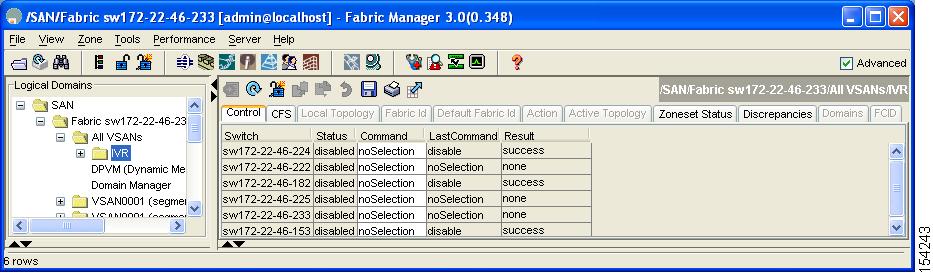
You see the IVR configuration in the Information pane (see Figure 2-1).
Figure 2-1 IVR Routing Configuration Control Tab
Step 2
Step 3
You see the service group dialog box.
Step 4
Step 5
Step 6
Step 7
Step 8
Autonomous Fabric IDs
The autonomous fabric ID (AFID) distinguishes segmented VSANS (for example, two VSANs that are logically and physically separate but have the same VSAN number). Cisco Fabric Manager Release 4.2(1) supports AFIDs 1 through 64. AFIDs are used in conjunction with IVR auto topology mode to allow segmented VSANs in the IVR VSAN topology database.
This section includes the following information about AFIDs:
•
Autonomous Fabric ID Guidelines
You can configure AFIDs individually for VSANs, or you can set the default AFIDs for all VSANs on a switch. If you configure an individual AFID for a subset of the VSANs on a switch that has a default AFID, that subset uses the configured AFID while all other VSANs on that switch use the default AFID.
You can only use an AFID configuration when the VSAN topology is in IVR auto topology mode. In IVR manual topology mode, the AFIDs are specified in the VSAN topology configuration itself and a separate AFID configuration is not needed.
Note
When devices attached to multiple switches belong to one VSAN, they cannot communicate with each other by configuring the regular zone set because the AFIDs are different. You can consider that the different AFIDs are different fabrics; therefore, the three switches represent three separate fabrics.
Configuring Default AFIDs
To configure default AFIDs using Fabric Manager, follow these steps:
Step 1
You see the IVR configuration in the Information pane.
Step 2
Step 3
Step 4
Step 5
Step 6
Step 7
Configuring Individual AFIDs
To configure individual AFIDs using Fabric Manager, follow these steps:
Step 1
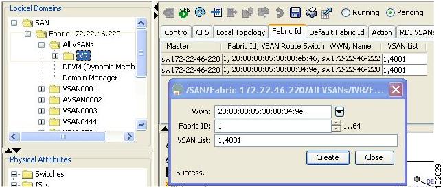
You see the IVR configuration in the Information pane.
Figure 2-2 Fabric ID Tab
Step 2
Step 3
Step 4
Step 5
Step 6
Step 7
Step 8
IVR Without IVR NAT or IVR Auto Topology Mode
This section includes the following sections on IVR without IVR NAT or IVR auto topology mode:
•
•
IVR Without IVR NAT or IVR Auto Topology Guidelines
Before configuring an IVR SAN fabric without IVR in NAT mode or IVR auto topology mode, consider the following general guidelines:
•
•
•
This section also includes the following:
Domain ID Guidelines
Before configuring domain IDs, consider the following guidelines:
•
–
–
•
•
You can configure domain IDs using one of two options:
•
•
Note
Transit VSAN Guidelines
Before configuring transit VSANS, consider the following guidelines:
•
–
–
•
•
Border Switch Guidelines
Before configuring border switches, consider the following guidelines:
•
•
•
•
•
•
Configuring IVR Without NAT
To enable IVR without NAT using Fabric Manager, follow these steps:
Step 1
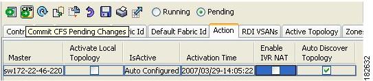
You see the IVR configuration in the Information pane.
Figure 2-3 Action Tab
Step 2
Step 3
Step 4
Manually Configuring and Activating an IVR Topology
You must create the IVR topology on every IVR-enabled switch in the fabric if you have not enabled IVR auto topology mode. To use IVR manual topology mode, follow the instructions in this section.
This section includes the following:
•
•
•
Manual Configuration Guidelines
Consider the following guidelines when using IVR manual topology mode:
•
•
–
–
–
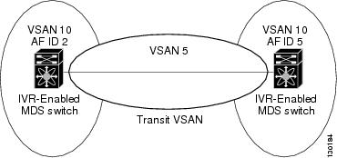
Figure 2-4 Example IVR Topology with Non-Unique VSAN IDs Using AFIDs
•
•
Manually Configuring an IVR Topology
You can configure IVR using the IVR tables in the Information pane in Fabric Manager. Use these tables only if you are familiar with all IVR concepts. We recommend you configure IVR using the IVR Wizard. See "Configuring IVR and IVR Zones Using the IVR Zone Wizard" on page 1-6.
Note
To manually configure an IVR topology using Fabric Manager, follow these steps:
Step 1
You see the IVR configuration in the Information pane.
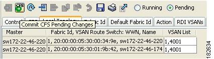
Figure 2-5 Local Topology Tab
Step 2
Step 3
Step 4
Step 5
Step 6
Repeat this configuration on all IVR-enabled switches or distribute the IVR configuration using CFS.
Tip
Activating a Manually Configured IVR Topology
After manually configuring the IVR topology, you must activate it.
Caution
To activate a manually configured IVR topology using Fabric Manager, follow these steps:
Step 1
You see the IVR configuration in the Information pane.
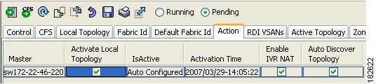
Figure 2-6 Action Tab
Step 2
Step 3
Step 4
Working with Existing IVR Topologies
This section includes advanced IVR configurations for existing IVR topologies:
•
•
Clearing a Manually Configured IVR Topology Database
To clear a manually created IVR topology database using Fabric Manager, follow these steps:
Step 1
Step 2
Step 3
Step 4
Step 5
Migrating from IVR Auto Topology Mode to IVR Manual Topology Mode
If you want to migrate from IVR auto topology mode to IVR manual topology mode, copy the active IVR VSAN topology database to the user-configured IVR VSAN topology database before switching modes.
To migrate from IVR auto topology mode to IVR manual topology mode using Fabric Manager, follow these steps:
Step 1
You see the IVR configuration in the Information pane.
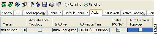
Figure 2-7 Action Tab
Step 2
Step 3
Step 4
Step 5
Persistent FC IDs for IVR
This section includes the following information:
•
FC ID Features and Benefits
FC ID persistence improves IVR management by providing the following features:
•
•
The benefits of persistent FC IDs for IVR are as follows:
•
•
•
FC ID Guidelines
Before configuring persistent FC IDs, consider the following:
•
–
Native AFID
Native VSAN
Current AFID
Current VSAN
Virtual domain to be used for the native AFID and VSAN in current AFID and VSAN
–
Port WWN
Current AFID
Current VSAN
Virtual FC ID to be used to represent a device for the given pWWN in the current AFID and VSAN
•
•
•
Configuring Persistent FC IDs for IVR
To configure persistent FC IDs for IVR using Fabric Manager, follow these steps:
Step 1
You see the IVR configuration in the Information pane.
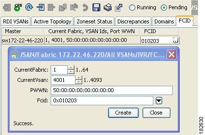
Figure 2-8 FCID Tab
Step 2
Step 3
Step 4
Step 5
Step 6
Step 7
Step 8
Step 9
Advanced IVR Zones and IVR Zone Sets
This section describes advanced configuration information for IVR zones and IVR zone sets. For basic information on configuring IVR zones and zone sets, see "IVR Zones and IVR Zone Sets" on page 1-14.
As part of the IVR configuration, you need to configure one or more IVR zone to enable cross-VSAN communication. To achieve this, you must specify each IVR zone as a set of (pWWN, VSAN) entries. Different IVR zone sets can contain the same IVR zone, because IVR zones can be members of one or more IVR zone sets.
Note
Caution
This section includes the following topics:
•
•
•
•
•
IVR Zone Configuration Guidelines
When interop mode is enabled, consider the following IVR configuration guidelines:
•
•
•
Configuring LUNs in IVR Zoning
LUN zoning can be used between members of active IVR zones.You can configure the service by creating and activating LUN zones between the desired IVR zone members in all relevant edge VSANs using the zoning interface or you can use LUN zoning directly supported by IVR. For more details on the advantages of LUN zoning, refer to the Cisco MDS 9000 Family NX-OS Fabric Configuration Guide or the Cisco Fabric Manager Fabric Configuration Guide.
Note
Configuring QoS for IVR Zones
To configure QoS for an IVR zone using Fabric Manager, follow these steps:
Note
Step 1
You see the Edit IVR Local Full Zone Database dialog box for the VSAN you selected.
Step 2
Step 3
Step 4
Renaming IVR Zones and IVR Zone Sets
To rename an IVR zone or IVR zone set, using Fabric Manager, follow these steps:
Step 1
You see the Edit IVR Local Full Zone Database dialog box for the VSAN you selected.
Step 2
Step 3
An edit box appears around the zone or zone set name.
Step 4
Step 5
Configuring IVR Using Read-Only Zoning
Read-only zoning (with or without LUNs) can be used between members of active IVR zones. To configure this service, you must create and activate read-only zones between the desired IVR zone members in all relevant edge VSANs using the zoning interface.
Note
Enabling Advanced Fabric Services on IVR Flows
Advanced fabric services (such as SME and IOA) use fabric-wide FC-Redirect infrastructure to redirect the traffic flows. These services can now be enabled on IVR flows using an internal feature, Abstract ACL Manager (AAM).
The steps to enable this functionality is listed in the following sub-sections:
•
Configuration Guidelines and Restrictions
The following prerequisites must be considered before enabling AAM for IVR:
•
•
•
•
•
•
•
•
•
•