Feedback
Table Of Contents
Generation 1 Interfaces Configuration Guidelines
Configuring Fibre Channel Interfaces
Setting the Interface Administrative State
Configuring System Default Port Mode F
Configuring Port Administrative Speeds
Configuring the Interface Description
Switch Port Attribute Default Values
Displaying Interface Information
Displaying TL Port Information
Manually Inserting Entries into ALPA Cache
Displaying the ALPA Cache Contents
Configuring Port Monitor Policy
Activating a Port Monitor Policy
Displaying Port Monitor Status and Policies
Configuring Port Group Monitor
Configuring Port Group Monitor Policy
Reverting to the Default Policy for a Specific Counter
Turning Off the Monitoring of Specific Counter
Activating a Port Group Monitor Policy
Displaying Port Group Monitor Status and Policies
Configuring Slow Drain Device Detection and Congestion Avoidance
About Slow Drain Device Detection and Congestion Avoidance
Configuring Stuck Frame Timeout Value
Configuring No-Credit Timeout Value
Configuring Credit Loss Recovery Threshold and Action
Configuring Average Credit Non-Available Duration Threshold and Action
Configuring Management Interfaces
Displaying Management Interface Configuration
Displaying VSAN Interface Information
Configuring Interfaces
The main function of a switch is to relay frames from one data link to another. To relay the frames, the characteristics of the interfaces through which the frames are received and sent must be defined. The configured interfaces can be Fibre Channel interfaces, Gigabit Ethernet interfaces, the management interface (mgmt0), or VSAN interfaces.
This chapter describes the basic interface configuration to get your switch up and running. It includes the following sections:
•
Configuring Port Group Monitor
•
For more information on configuring mgmt0 interfaces, refer to the Cisco MDS 9000 Family NX-OS Fundamentals Configuration Guide and Cisco MDS 9000 Family NX-OS IP Services Configuration Guide.
See the Cisco MDS 9000 Family NX-OS IP Services Configuration Guide for more information on configuring Gigabit Ethernet interfaces.
Tip
Tip
Fibre Channel Interfaces
This section describes Fibre Channel interface characteristics, including (but not limited to) modes, frame encapsulation, states, SFPs, and speeds.
This section includes the following topics:
•
•
•
•
•
•
Generation 1 Interfaces Configuration Guidelines
The Generation 1 interfaces configuration guidelines apply to the following hardware:
•
•
Note
When configuring these host-optimized ports, the following port mode guidelines apply:
•
•
•
•
•
•
Note
Note
About Interface Modes
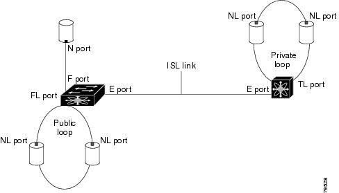
Each physical Fibre Channel interface in a switch may operate in one of several port modes: E port, F port, FL port, TL port, TE port, SD port, ST port, and B port (see Figure 2-1). Besides these modes, each interface may be configured in auto or Fx port modes. These two modes determine the port type during interface initialization.
Figure 2-1 Cisco MDS 9000 Family Switch Port Modes
Note
Each interface has an associated administrative configuration and an operational status:
•
•
Note
Each interface is briefly described in the sections that follow.
E Port
In expansion port (E port) mode, an interface functions as a fabric expansion port. This port may be connected to another E port to create an Inter-Switch Link (ISL) between two switches. E ports carry frames between switches for configuration and fabric management. They serve as a conduit between switches for frames destined to remote N ports and NL ports. E ports support class 2, class 3, and class F service.
An E port connected to another switch may also be configured to form a PortChannel (see Chapter 6 "Configuring PortChannels").
Note
F Port
In fabric port (F port) mode, an interface functions as a fabric port. This port may be connected to a peripheral device (host or disk) operating as an N port. An F port can be attached to only one N port. F ports support class 2 and class 3 service.
FL Port
In fabric loop port (FL port) mode, an interface functions as a fabric loop port. This port may be connected to one or more NL ports (including FL ports in other switches) to form a public arbitrated loop. If more than one FL port is detected on the arbitrated loop during initialization, only one FL port becomes operational and the other FL ports enter nonparticipating mode. FL ports support class 2 and class 3 service.
Note
NP Ports
An NP port is a port on a device that is in NPV mode and connected to the core switch via an F port. NP ports function like N ports except that in addition to providing N port operations, they also function as proxies for multiple, physical N ports.
For more details about NP ports and NPV, see Chapter 7 "Configuring N Port Virtualization.".
TL Port
In translative loop port (TL port) mode, an interface functions as a translative loop port. It may be connected to one or more private loop devices (NL ports). TL ports are specific to Cisco MDS 9000 Family switches and have similar properties as FL ports. TL ports enable communication between a private loop device and one of the following devices:
•
•
•
•
TL ports support class 2 and class 3 services.
Private loop devices refer to legacy devices that reside on arbitrated loops. These devices are not aware of a switch fabric because they only communicate with devices on the same physical loop (see the "About TL Port ALPA Caches" section).
Tip
Note
TE Port
In trunking E port (TE port) mode, an interface functions as a trunking expansion port. It may be connected to another TE port to create an extended ISL (EISL) between two switches. TE ports are specific to Cisco MDS 9000 Family switches. They expand the functionality of E ports to support the following:
•
•
•
In TE port mode, all frames are transmitted in EISL frame format, which contains VSAN information. Interconnected switches use the VSAN ID to multiplex traffic from one or more VSANs across the same physical link. This feature is referred to as trunking in the Cisco MDS 9000 Family switches (see Chapter 5 "Configuring Trunking"). TE ports support class 2, class 3, and class F service.
TF Port
In trunking F port (TF port) mode, an interface functions as a trunking expansion port. It may be connected to another trunked N port (TN port) or trunked NP port (TNP port) to create a link between a core switch and an NPV switch or an HBA to carry tagged frames. TF ports are specific to Cisco MDS 9000 Family switches. They expand the functionality of F ports to support VSAN trunking.
In TF port mode, all frames are transmitted in EISL frame format, which contains VSAN information. Interconnected switches use the VSAN ID to multiplex traffic from one or more VSANs across the same physical link. This feature is referred to as trunking in the Cisco MDS 9000 Family (see Chapter 5 "Configuring Trunking"). TF ports support class 2, class 3, and class F service.
TNP Port
In trunking NP port (TNP port) mode, an interface functions as a trunking expansion port. It may be connected to a trunked F port (TF port) to create a link to a core NPIV switch from an NPV switch to carry tagged frames.
SD Port
In SPAN destination port (SD port) mode, an interface functions as a switched port analyzer (SPAN). The SPAN feature is specific to switches in the Cisco MDS 9000 Family. It monitors network traffic that passes though a Fibre Channel interface. This monitoring is done using a standard Fibre Channel analyzer (or a similar switch probe) that is attached to an SD port. SD ports do not receive frames, they only transmit a copy of the source traffic. The SPAN feature is nonintrusive and does not affect switching of network traffic for any SPAN source ports (see the Cisco MDS 9000 Family NX-OS System Management Configuration Guide).
ST Port
In the SPAN tunnel port (ST port) mode, an interface functions as an entry point port in the source switch for the RSPAN Fibre Channel tunnel. The ST port mode and the remote SPAN (RSPAN) feature are specific to switches in the Cisco MDS 9000 Family. When configured in ST port mode, the interface cannot be attached to any device, and thus cannot be used for normal Fibre Channel traffic (see the Cisco MDS 9000 Family NX-OS System Management Configuration Guide).
Note
Fx Port
Interfaces configured as Fx ports can operate in either F port or FL port mode. The Fx port mode is determined during interface initialization depending on the attached N port or NL port. This administrative configuration disallows interfaces to operate in any other mode—for example, preventing an interface to connect to another switch.
B Port
While E ports typically interconnect Fibre Channel switches, some SAN extender devices, such as the Cisco PA-FC-1G Fibre Channel port adapter, implement a bridge port (B port) model to connect geographically dispersed fabrics. This model uses B ports as described in the T11 Standard FC-BB-2.
If an FCIP peer is a SAN extender device that only supports Fibre Channel B ports, you need to enable the B port mode for the FCIP link. When a B port is enabled, the E port functionality is also enabled and they coexist. If the B port is disabled, the E port functionality remains enabled (see the Cisco MDS 9000 Family NX-OS IP Services Configuration Guide).
Auto Mode
Interfaces configured in auto mode can operate in one of the following modes: F port, FL port, E port, TE port, or TF port. The port mode is determined during interface initialization. For example, if the interface is connected to a node (host or disk), it operates in F port or FL port mode depending on the N port or NL port mode. If the interface is attached to a third-party switch, it operates in E port mode. If the interface is attached to another switch in the Cisco MDS 9000 Family, it may become operational in TE port mode (see Chapter 5 "Configuring Trunking").
TL ports and SD ports are not determined during initialization and are administratively configured.
Note
About Interface States
The interface state depends on the administrative configuration of the interface and the dynamic state of the physical link.
Administrative States
The administrative state refers to the administrative configuration of the interface as described in Table 2-1.
Operational States
The operational state indicates the current operational state of the interface as described in Table 2-2.
Reason Codes
Reason codes are dependent on the operational state of the interface as described in Table 2-3.
Table 2-3 Reason Codes for Interface States
Up
Up
None.
Down
Down
Administratively down—If you administratively configure an interface as down, you disable the interface. No traffic is received or transmitted.
Up
Down
See Table 2-4.
Note
If the administrative state is up and the operational state is down, the reason code differs based on the nonoperational reason code as described in Table 2-4.
Configuring Fibre Channel Interfaces
To configure a Fibre Channel interface, follow these steps:
To configure a range of interfaces, follow these steps:
For the Cisco Fabric Switch for HP c-Class BladeSystem and the Cisco Fabric Switch for IBM BladeCenter, you can configure a range of interfaces among internal ports or external ports, but you cannot mix both interface types within the same range. For example, "bay 1-10, bay 12" or "ext 0, ext 15-18" are valid ranges, but "bay 1-5, ext 15-17" is not.
Graceful Shutdown
Interfaces on a port are shut down by default (unless you modified the initial configuration).
The Cisco NX-OS software implicitly performs a graceful shutdown in response to either of the following actions for interfaces operating in the E port mode:
•
•
A graceful shutdown ensures that no frames are lost when the interface is shutting down. When a shutdown is triggered either by you or the Cisco NX-OS software, the switches connected to the shutdown link coordinate with each other to ensure that all frames in the ports are safely sent through the link before shutting down. This enhancement reduces the chance of frame loss.
A graceful shutdown is not possible in the following situations:
•
•
•
Note
Setting the Interface Administrative State
To gracefully shut down an interface, follow these steps:
To enable traffic flow, follow these steps:
Configuring Interface Modes
To configure the interface mode, follow these steps:
Configuring System Default Port Mode F
The system default switchport mode F command sets the administrative mode of all Fibre Channel ports to mode F, while avoiding traffic disruption caused by the formation of unwanted Inter-Switch Links (ISLs). This command is part of the setup utility that runs during bootup after a write erase or reload. It can also be executed from the command line in configuration mode. This command changes the configuration of the following ports to administrative mode F:
•
•
This command does not affect the configuration of the following ports:
•
•
Example 2-1 shows the command in the setup utility, and Example 2-2 shows the command from the command line.
Example 2-1 Setup Utility
Configure default switchport mode F (yes/no) [n]: yExample 2-2 Command Line
switch(config)# system default switchport mode F
Note
Note
To set the administrative mode of Fibre Channel ports to mode F in the CLI, follow these steps:
Note
Configuring Port Administrative Speeds
By default, the port administrative speed for an interface is automatically calculated by the switch.
Caution
To configure the port speed of the interface, follow these steps:
For internal ports on the Cisco Fabric Switch for HP c_Class BladeSystem and Cisco Fabric Switch for IBM BladeCenter, a port speed of 1 Gbps is not supported. Auto-negotiation is supported between 2 Gbps and 4 Gbps only. Also, if the BladeCenter is a T chassis, then port speeds are fixed at 2 Gbps and auto-negotiation is not enabled.
Autosensing
Autosensing speed is enabled on all 4-Gbps and 8-Gbps switching module interfaces by default. This configuration enables the interfaces to operate at speeds of 1 Gbps, 2 Gbps, or 4 Gbps on the 4-Gbps switching modules, and 8 Gbps on the 8-Gbps switching modules. When autosensing is enabled for an interface operating in dedicated rate mode, 4 Gbps of bandwidth is reserved, even if the port negotiates at an operating speed of 1 Gbps or 2 Gbps.
To avoid wasting unused bandwidth on 48-port and 24-port 4-Gbps and 8-Gbps Fibre Channel switching modules, you can specify that only 2 Gbps of required bandwidth be reserved, not the default of 4 Gbps or 8 Gbps. This feature shares the unused bandwidth within the port group provided that it does not exceed the rate limit configuration for the port. You can also use this feature for shared rate ports that are configured for autosensing.
Tip
Configuring the Interface Description
Interface descriptions enable you to identify the traffic or the use for that interface. The interface description can be any alphanumeric string.
To configure a description for an interface, follow these steps:
Specifying a Port Owner
Using the port owner feature, you can specify the owner of a port and the purpose for which a port is used so that the other administrators are informed.
To specify or remove the port owner, follow these steps:
Note
To display the owner description specified for a port, use the following commands:
switch# show running interface fc module-number/interface-numberswitch# show port internal info interface fc module-number/interface-numberFrame Encapsulation
The switchport encap eisl command only applies to SD port interfaces. This command determines the frame format for all frames transmitted by the interface in SD port mode. If the encapsulation is set to EISL, all outgoing frames are transmitted in the EISL frame format, regardless of the SPAN sources.
The switchport encap eisl command is disabled by default. If you enable encapsulation, all outgoing frames are encapsulated, and you will see a new line (Encapsulation is eisl) in the show interface SD_port_interface command output. See the Cisco MDS 9000 Family NX-OS System Management Configuration Guide.
Identifying the Beacon LEDs
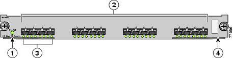
Figure 2-2 displays the status, link, and speed LEDs in a 16-port switching module.
Figure 2-2 Cisco MDS 9000 Family Switch Interface Modes
Status LED1
Link LEDs1 and speed LEDs2
1/2-Gbps Fibre Channel port group3
Asset tag4
1 See the Cisco MDS 9000 Family NX-OS Fundamentals Configuration Guide.
2 See the "About Speed LEDs" section.
3 See the "Generation 1 Interfaces Configuration Guidelines" section.
4 Refer to the Cisco MDS 9000 Family hardware installation guide for your platform.
About Speed LEDs
Each port has one link LED on the left and one speed LED on the right.
The speed LED displays the speed of the port interface:
•
•
The speed LED also displays if the beacon mode is enabled or disabled:
•
•
Note
Configuring Beacon Mode
By default, the beacon mode is disabled on all switches. The beacon mode is indicated by a flashing green light that helps you identify the physical location of the specified interface. Configuring the beacon mode has no effect on the operation of the interface.
To enable beacon mode for a specified interface or range of interfaces, follow these steps:
Note
About Bit Error Thresholds
The bit error rate threshold is used by the switch to detect an increased error rate before performance degradation seriously affects traffic.
The bit errors can occur for the following reasons:
•
•
•
•
•
•
•
•
A bit error rate threshold is detected when 15 error bursts occur in a 5-minute period. By default, the switch disables the interface when the threshold is reached. You can enter a shutdown and no shutdown command sequence to reenable the interface.
You can configure the switch to not disable an interface when the threshold is crossed. By default, the threshold disables the interface.
To disable the bit error threshold for an interface, follow these steps:
Note
Switch Port Attribute Default Values
You can configure attribute default values for various switch port attributes. These attributes will be applied globally to all future switch port configurations, even if you do not individually specify them at that time.
To configure switch port attributes, follow these steps:
About SFP Transmitter Types
The small form-factor pluggable (SFP) hardware transmitters are identified by their acronyms when displayed. Table 2-5 defines the acronyms used for SFPs.
The small form-factor pluggable (SFP) hardware transmitters are identified by their acronyms when displayed in the show interface brief command. If the related SFP has a Cisco-assigned extended ID, then the show interface and show interface brief commands display the ID instead of the transmitter type. The show interface transceiver command and the show interface fcs lot/port transceiver command display both values for Cisco-supported SFPs. Table 2-5 defines the acronyms used in the command output (see the "Displaying Interface Information" section).
Displaying Interface Information
The show interface command is invoked from the EXEC mode and displays the interface configurations. Without any arguments, this command displays the information for all the configured interfaces in the switch. See Examples 2-3 to 2-10.
Example 2-3 Displays All Interfaces
switch# show interfacefc1/1 is upHardware is Fibre Channel, SFP is short wave laserPort WWN is 20:0b:00:05:30:00:8d:deAdmin port mode is FPort mode is F, FCID is 0x610000Port vsan is 2Speed is 2 GbpsTransmit B2B Credit is 3Receive B2B Credit is 16Receive data field Size is 2112Beacon is turned off5 minutes input rate 0 bits/sec, 0 bytes/sec, 0 frames/sec5 minutes output rate 0 bits/sec, 0 bytes/sec, 0 frames/sec134 frames input, 8468 bytes0 discards, 0 errors0 CRC, 0 unknown class0 too long, 0 too short154 frames output, 46072 bytes0 discards, 0 errors1 input OLS, 1 LRR, 0 NOS, 0 loop inits1 output OLS, 0 LRR, 1 NOS, 0 loop inits16 receive B2B credit remaining3 transmit B2B credit remaining.. . .fc1/9 is trunkingHardware is Fibre Channel, SFP is long wave laser cost reducedPort WWN is 20:09:00:05:30:00:97:9ePeer port WWN is 20:0b:00:0b:5f:a3:cc:00Admin port mode is E, trunk mode is onPort mode is TEPort vsan is 100Speed is 2 GbpsTransmit B2B Credit is 255Receive B2B Credit is 255Receive data field Size is 2112Beacon is turned offTrunk vsans (admin allowed and active) (1,100,3000)Trunk vsans (up) (1,100,3000)Trunk vsans (isolated) ()Trunk vsans (initializing) ()5 minutes input rate 280 bits/sec, 35 bytes/sec, 0 frames/sec5 minutes output rate 176 bits/sec, 22 bytes/sec, 0 frames/sec4609939 frames input, 8149405708 bytes0 discards, 0 errors0 CRC, 0 unknown class0 too long, 0 too short4638491 frames output, 7264731728 bytes0 discards, 0 errors3 input OLS, 9 LRR, 1 NOS, 0 loop inits9 output OLS, 7 LRR, 1 NOS, 0 loop inits16 receive B2B credit remaining3 transmit B2B credit remaining.. . .fc1/13 is upHardware is Fibre Channel, SFP is short wave laserPort WWN is 20:0d:00:05:30:00:97:9eAdmin port mode is auto, trunk mode is onPort mode is F, FCID is 0x650100Port vsan is 100Speed is 2 GbpsTransmit B2B Credit is 3Receive B2B Credit is 16Receive data field Size is 2112Beacon is turned off5 minutes input rate 0 bits/sec, 0 bytes/sec, 0 frames/sec5 minutes output rate 0 bits/sec, 0 bytes/sec, 0 frames/sec8696 frames input, 3227212 bytes0 discards, 0 errors0 CRC, 0 unknown class0 too long, 0 too short16799 frames output, 6782444 bytes0 discards, 0 errors0 input OLS, 0 LRR, 0 NOS, 0 loop inits1 output OLS, 1 LRR, 0 NOS, 1 loop inits16 receive B2B credit remaining3 transmit B2B credit remaining.. . .sup-fc0 is upHardware is Fibre ChannelSpeed is 1 Gbps139597 packets input, 13852970 bytes0 multicast frames, 0 compressed0 input errors, 0 frame, 0 overrun 0 fifo139516 packets output, 16759004 bytes, 0 underruns0 output errors, 0 collisions, 0 fifo0 carrier errorsYou can also specify arguments (a range of interfaces or multiple, specified interfaces) to display interface information. You can specify a range of interfaces by issuing a command with the following example format:
interface fc1/1 - 5 , fc2/5 - 7
Note
Example 2-4 Displays Multiple, Specified Interfaces
switch# show interface fc3/13 , fc3/16fc3/13 is upHardware is Fibre Channel, SFP is short wave laserPort WWN is 20:8d:00:05:30:00:97:9eAdmin port mode is FXPort mode is F, FCID is 0x7b0300Port vsan is 1Speed is 2 GbpsTransmit B2B Credit is 3Receive B2B Credit is 12Receive data field Size is 2112Beacon is turned off5 minutes input rate 0 bits/sec, 0 bytes/sec, 0 frames/sec5 minutes output rate 0 bits/sec, 0 bytes/sec, 0 frames/sec1856 frames input, 116632 bytes0 discards, 0 errors0 CRC, 0 unknown class0 too long, 0 too short1886 frames output, 887712 bytes0 discards, 0 errors0 input OLS, 0 LRR, 0 NOS, 1 loop inits1 output OLS, 1 LRR, 0 NOS, 1 loop inits16 receive B2B credit remaining3 transmit B2B credit remaining.fc3/16 is upHardware is Fibre Channel, SFP is short wave laserPort WWN is 20:90:00:05:30:00:97:9eAdmin port mode is FXPort mode is F, FCID is 0x7d0100Port vsan is 3000Speed is 2 GbpsTransmit B2B Credit is 3Receive B2B Credit is 12Receive data field Size is 2112Beacon is turned off5 minutes input rate 504 bits/sec, 63 bytes/sec, 0 frames/sec5 minutes output rate 520 bits/sec, 65 bytes/sec, 0 frames/sec47050 frames input, 10311824 bytes0 discards, 0 errors0 CRC, 0 unknown class0 too long, 0 too short62659 frames output, 10676988 bytes0 discards, 0 errors0 input OLS, 0 LRR, 0 NOS, 0 loop inits1 output OLS, 1 LRR, 0 NOS, 1 loop inits16 receive B2B credit remaining3 transmit B2B credit remaining.Example 2-5 Displays a Specific Interface
switch# show interface fc2/2fc2/2 is trunkingPort description is Trunk to Core-4Hardware is Fibre Channel, SFP is short wave laserPort WWN is 20:42:00:05:30:00:97:9ePeer port WWN is 20:cc:00:05:30:00:50:9eAdmin port mode is E, trunk mode is onPort mode is TEPort vsan is 1Speed is 2 GbpsTransmit B2B Credit is 255Receive B2B Credit is 255Receive data field Size is 2112Beacon is turned offBelongs to port-channel 2Trunk vsans (admin allowed and active) (1,100,3000)Trunk vsans (up) (1)Trunk vsans (isolated) (100,3000)Trunk vsans (initializing) ()5 minutes input rate 0 bits/sec, 0 bytes/sec, 0 frames/sec5 minutes output rate 32 bits/sec, 4 bytes/sec, 0 frames/sec2214834 frames input, 98673588 bytes0 discards, 0 errors0 CRC, 0 unknown class0 too long, 0 too short2262415 frames output, 343158368 bytes0 discards, 0 errors1 input OLS, 1 LRR, 1 NOS, 0 loop inits2 output OLS, 1 LRR, 0 NOS, 0 loop inits16 receive B2B credit remaining3 transmit B2B credit remaining.Example 2-6 Displays Port Description
switch# show interface description-------------------------------------------------------------------------------Interface Description-------------------------------------------------------------------------------fc3/1 test intestfc3/2 --fc3/3 --fc3/4 TE portfc3/5 --fc3/6 --fc3/10 Next hop switch 5fc3/11 --fc3/12 --fc3/16 ---------------------------------------------------------------------------------Interface Description-------------------------------------------------------------------------------port-channel 1 --port-channel 5 --port-channel 6 --Example 2-7 Displays Interface Information in a Brief Format
switch# show interface brief-------------------------------------------------------------------------------Interface Vsan Admin Admin Status SFP Oper Oper PortMode Trunk Mode Speed ChannelMode (Gbps)-------------------------------------------------------------------------------fc1/1 1 E on trunking swl TE 2 1fc1/2 1 E on trunking swl TE 2 1fc1/3 1 auto on SFPAbsent -- -- --fc1/4 1 auto on SFPAbsent -- -- --fc1/5 3000 auto on up swl F 2 --...fc2/2 1 E on trunking swl TE 2 2fc2/3 1 auto on down c1610 -- --fc2/4 1 auto on down c1590 -- --fc2/5 3000 auto on notConnected lwcr -- --fc2/6 1 auto on SFPAbsent -- -- --...fc3/16 3000 FX -- up swl F 2 --fc3/17 1 FX -- SFPAbsent -- -- --...-------------------------------------------------------------------------------Interface Status IP Address Speed MTU-------------------------------------------------------------------------------GigabitEthernet4/1 SFPAbsent -- auto 1500...GigabitEthernet4/6 down 10.1.1.2/8 auto 3000GigabitEthernet4/7 down 10.1.1.27/24 auto 1500GigabitEthernet4/8 down -- auto 1500-------------------------------------------------------------------------------Interface Status Oper Mode Oper Speed(Gbps)-------------------------------------------------------------------------------iscsi4/1 down --...-------------------------------------------------------------------------------Interface Status Speed(Gbps)-------------------------------------------------------------------------------sup-fc0 up 1-------------------------------------------------------------------------------Interface Status IP Address Speed MTU-------------------------------------------------------------------------------mgmt0 up 172.19.48.96/25 100 Mbps 1500-------------------------------------------------------------------------------Interface Vsan Admin Status Oper OperTrunk Mode SpeedMode (Gbps)-------------------------------------------------------------------------------port-channel 1 1 on trunking TE 4port-channel 2 1 on trunking TE 4-------------------------------------------------------------------------------Interface Vsan Admin Admin Status Oper Profile Port-channelMode Trunk ModeMode-------------------------------------------------------------------------------fcip10 1 auto on notConnected -- 10 --Example 2-8 Displays Interface Counters
switch# show interface countersfc3/15 minutes input rate 24 bits/sec, 3 bytes/sec, 0 frames/sec5 minutes output rate 16 bits/sec, 2 bytes/sec, 0 frames/sec3502 frames input, 268400 bytes0 discards, 0 CRC, 0 unknown class0 too long, 0 too short3505 frames output, 198888 bytes0 discards1 input OLS, 1 LRR, 1 NOS, 0 loop inits2 output OLS, 1 LRR, 1 NOS, 0 loop inits1 link failures, 1 sync losses, 1 signal losses...fc9/85 minutes input rate 0 bits/sec, 0 bytes/sec, 0 frames/sec5 minutes output rate 0 bits/sec, 0 bytes/sec, 0 frames/sec0 frames input, 0 bytes0 class-2 frames, 0 bytes0 class-3 frames, 0 bytes0 class-f frames, 0 bytes0 discards, 0 CRC, 0 unknown class0 too long, 0 too short0 frames output, 0 bytes0 class-2 frames, 0 bytes0 class-3 frames, 0 bytes0 class-f frames, 0 bytes0 discards0 input OLS, 0 LRR, 0 NOS, 0 loop inits0 output OLS, 0 LRR, 0 NOS, 0 loop inits0 link failures, 0 sync losses, 0 signal losses16 receive B2B credit remaining3 transmit B2B credit remaining.. . .sup-fc0114000 packets input, 11585632 bytes0 multicast frames, 0 compressed0 input errors, 0 frame, 0 overrun 0 fifo113997 packets output, 10969672 bytes, 0 underruns0 output errors, 0 collisions, 0 fifo0 carrier errorsmgmt031557 packets input, 2230860 bytes0 multicast frames, 0 compressed0 input errors, 0 frame, 0 overrun 0 fifo26618 packets output, 16824342 bytes, 0 underruns0 output errors, 0 collisions, 7 fifo0 carrier errorsvsan10 packets input, 0 bytes, 0 errors, 0 multicast0 packets output, 0 bytes, 0 errors, 0 dropped...port-channel 15 minutes input rate 0 bits/sec, 0 bytes/sec, 0 frames/sec5 minutes output rate 0 bits/sec, 0 bytes/sec, 0 frames/sec0 frames input, 0 bytes0 class-2 frames, 0 bytes0 class-3 frames, 0 bytes0 class-f frames, 0 bytes0 discards, 0 CRC, 0 unknown class0 too long, 0 too short0 frames output, 0 bytes0 class-2 frames, 0 bytes0 class-3 frames, 0 bytes0 class-f frames, 0 bytes0 discards0 input OLS, 0 LRR, 0 NOS, 0 loop inits0 output OLS, 0 LRR, 0 NOS, 0 loop inits0 link failures, 0 sync losses, 0 signal losses
Note
Example 2-9 Displays Interface Counters in Brief Format
switch# show interface counters brief-------------------------------------------------------------------------------Interface Input (rate is 5 min avg) Output (rate is 5 min avg)----------------------------- -----------------------------Rate Total Rate TotalMbits/s Frames Mbits/s Frames-------------------------------------------------------------------------------fc3/1 0 3871 0 3874fc3/2 0 3902 0 4232fc3/3 0 3901 0 4138fc3/4 0 3895 0 3894fc3/5 0 3890 0 3897fc9/8 0 0 0 0fc9/9 0 5 0 4fc9/10 0 4186 0 4182fc9/11 0 4331 0 4315-------------------------------------------------------------------------------Interface Input (rate is 5 min avg) Output (rate is 5 min avg)----------------------------- -----------------------------Rate Total Rate TotalMbits/s Frames Mbits/s Frames-------------------------------------------------------------------------------port-channel 1 0 0 0 0port-channel 2 0 3946 0 3946
Note
Example 2-10 Displays Transceiver Information
switch# show interface transceiverfc1/1 SFP is presentname is CISCO-AGILENTpart number is QFBR-5796Lrevision isserial number is A00162193fc-transmitter type is short wave lasercisco extended id is unknown (0x0)...fc1/9 SFP is presentname is FINISAR CORP.part number is FTRJ-1319-7D-CSCrevision isserial number is H11A6ERfc-transmitter type is long wave laser cost reducedcisco extended id is unknown (0x0)...Example 2-11 displays the entire running configuration with information for all interfaces. The interfaces have multiple entries in the configuration files to ensure that the interface configuration commands execute in the correct order when the switch reloads.
Example 2-11 Displays the Running Configuration for All Interfaces
switch# show running-config...interface fc9/1switchport speed 2000...interface fc9/1switchport mode E...interface fc9/1channel-group 11 forceno shutdownExample 2-12 displays the running configuration information for a specified interface. The interface configuration commands are grouped together.
Example 2-12 Displays the Running Configuration for a Specified Interface
switch# show running-config interface fc1/1interface fc9/1switchport speed 2000switchport mode Echannel-group 11 forceno shutdownExample 2-13 displays the running configuration after the system default switchport mode F command is executed. Example 2-14 displays the running configuration after two interfaces are individually configured for mode FL.
Example 2-13 Displays the Running Configuration After the System Default Switchport Mode F Command is Executed
switch# show running-configversion 3.1(3)system default switchport mode Finterface fc4/1interface fc4/2interface fc4/3interface fc4/4interface fc4/5interface fc4/6interface fc4/7interface fc4/8interface fc4/9interface fc4/10Example 2-14 Displays the Running Configuration After Two Interfaces Are Individually Configured for Mode FL
switch# show running-configversion 3.1(3)system default switchport mode Finterface fc4/1switchport mode FLinterface fc4/2interface fc4/3switchport mode FLinterface fc4/4interface fc4/5interface fc4/6interface fc4/7interface fc4/8interface fc4/9interface fc4/1Example 2-15 displays interface information in a brief format after the system default switchport mode F command is executed. Example 2-16 displays interface information in a brief format after two interfaces are individually configured for mode FL.
Example 2-15 Displays Interface Information in a Brief Format After the System Default Switchport Mode F Command is Executed
switch# show interface brief-------------------------------------------------------------------------------Interface Vsan Admin Admin Status SFP Oper Oper PortMode Trunk Mode Speed ChannelMode (Gbps)-------------------------------------------------------------------------------fc4/1 1 F -- notConnected swl -- --fc4/2 1 F -- notConnected swl -- --fc4/3 1 F -- notConnected swl -- --fc4/4 1 F -- notConnected swl -- --fc4/5 1 F -- sfpAbsent -- -- --fc4/6 1 F -- sfpAbsent -- -- --fc4/7 1 F -- sfpAbsent -- -- --fc4/8 1 F -- sfpAbsent -- -- --fc4/9 1 F -- sfpAbsent -- -- --Example 2-16 Displays Interface Information in a Brief Format After Two Interfaces Are Individually Configured for Mode FL
switch# show interface brief-------------------------------------------------------------------------------Interface Vsan Admin Admin Status SFP Oper Oper PortMode Trunk Mode Speed ChannelMode (Gbps)-------------------------------------------------------------------------------fc4/1 1 FL -- notConnected swl -- --fc4/2 1 F -- notConnected swl -- --fc4/3 1 FL -- notConnected swl -- --fc4/4 1 F -- notConnected swl -- --fc4/5 1 F -- sfpAbsent -- -- --fc4/6 1 F -- sfpAbsent -- -- --fc4/7 1 F -- sfpAbsent -- -- --fc4/8 1 F -- sfpAbsent -- -- --fc4/9 1 F -- sfpAbsent -- -- --fc4/10 1 F -- sfpAbsent -- -- --TL Ports for Private Loops
Private loops require setting the interface mode to TL. This section describes TL ports and includes the following sections:
•
•
•
About TL Ports
Private loop devices refer to legacy devices that reside on arbitrated loops. These devices are not aware of a switch fabric because they only communicate with devices on the same physical loop. The legacy devices are used in Fibre Channel networks, and devices outside the loop may need to communicate with them. The communication functionality is provided through TL ports. See the "About Interface Modes" section.
TL port mode is not supported on the following hardware:
•
•
•
•
Follow these guidelines when configuring private loops:
•
•
•
•
•
•
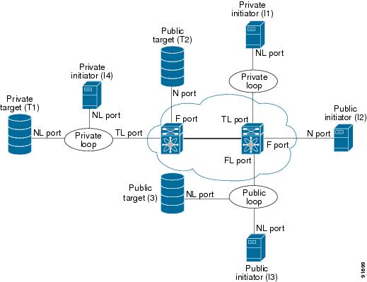
Table 2-6 lists the TL port translations supported in Cisco MDS 9000 Family switches.
Figure 2-3 shows examples of TL port translation support.
Figure 2-3 TL Port Translation Support Examples
Configuring TL Ports
Use the switchport mode command to configure a TL port. See the "Configuring Interface Modes" section.
About TL Port ALPA Caches
Although TL ports cannot be automatically configured, you can manually configure entries in arbitrated loop physical address (ALPA) caches. Generally, ALPA cache entries are automatically populated when an ALPA is assigned to a device. Each device is identified by its port world wide name (pWWN). When a device is allocated an ALPA, an entry for that device is automatically created in the ALPA cache.
A cache contains entries for recently allocated ALPA values. These caches are maintained on various TL ports. If a device already has an ALPA, the Cisco NX-OS software attempts to allocate the same ALPA to the device each time. The ALPA cache is maintained in persistent storage and saves information across switch reboots. The maximum cache size is 1000 entries. If the cache is full, and a new ALPA is allocated, the Cisco NX-OS software discards an inactive cache entry (if available) to make space for the new entry. See the "TL Port" section for more information on TL ports.
Displaying TL Port Information
The show tlport command displays the TL port interface configurations. This command provides a list of all TL ports configured in a switch and shows the associated VSAN, the FC ID for the port (only domain and area are valid), and the current operational state of the TL port (up or initializing). See Example 2-17 through Example 2-20.
Example 2-17 Displays the TL Ports in All VSANs
switch# show tlport list-------------------------------Interface Vsan FC-ID State------------------------- ------fc1/16 1 0x420000 Initfc2/26 1 0x150000 UpTL ports allow a private device (devices that physically reside on the loop) to see a fabric device and vice-versa by proxying fabric devices on the loop. Fabric devices are proxied by allocating each fabric device an ALPA on this loop.
In addition to these proxied devices, other virtual devices (local or remote domain controller addresses) are also allocated ALPAs on the loop. A switch reserves the ALPA for its own communication with private devices, and the switch acts as a SCSI initiator.
The first column in the output of the show tlport interface command is the ALPA identity of the device on the loop. The columns that follow include the port WWNs, the node WWNs for each device, the device as a SCSI initiator or target, and the real FC ID of the device.
Example 2-18 Displays the Detailed Information for a Specific TL Port
switch# show tlport interface fc1/16 allfc1/16 is up, vsan 1, FCID 0x420000-------------------------------------------------------------------------------- alpa pWWN nWWN SCSI Type Device FC-ID -------------------------------------------------------------------------------- 0x01 20:10:00:05:30:00:4a:de 20:00:00:05:30:00:4a:de Initiator Proxied 0xfffc42 0x73 22:00:00:20:37:39:ae:54 20:00:00:20:37:39:ae:54 Target Private 0x420073 0xef 20:10:00:05:30:00:4a:de 20:00:00:05:30:00:4a:de Initiator Switch 0x0000efExample 2-19 Displays TL Port Information for Private Devices
switch# show tlport interface fc 1/16 privatefc1/16 is up, vsan 1, FCID 0x420000------------------------------------------------------------------------alpa pWWN nWWN SCSI Type FC-ID ------------------------------------------------------------------------0x73 22:00:00:20:37:39:ae:54 20:00:00:20:37:39:ae:54 Target 0x4200730x74 22:00:00:20:37:38:d3:de 20:00:00:20:37:38:d3:de Target 0x420074Example 2-20 Displays TL Port Information for Proxied Devices
switch# show tlport interface fc 1/16 proxiedfc1/16 is up, vsan 1, FCID 0x420000------------------------------------------------------------------------alpa pWWN nWWN SCSI Type FC-ID ------------------------------------------------------------------------0x01 20:10:00:05:30:00:4a:de 20:00:00:05:30:00:4a:de Initiator 0xfffc420x02 21:00:00:e0:8b:01:95:e7 20:00:00:e0:8b:01:95:e7 Initiator 0x420100Manually Inserting Entries into ALPA Cache
To manually insert entries into the ALPA cache, follow these steps:
Displaying the ALPA Cache Contents
The show tlport alpa-cache command displays the contents of the ALPA cache.
switch# show tlport alpa-cache---------------------------------------------------------alpa pWWN Interface---------------------------------------------------------0x02 22:00:00:20:37:46:09:bd fc1/20x04 23:00:00:20:37:46:09:bd fc1/2The first entry indicates that if a device with a pWWN of 22:00:00:20:37:46:09:bd is exported on TL port fc1/2, then the pWWN is allocated an alpa 0x02 (if available).
Clearing the ALPA Cache
The clear tlport alpa-cache command clears the entire content of the ALPA cache.
Configuring Port Guard
The port guard feature is intended for use in environments where the system and application environment does not adapt quickly and efficiently to a port going down and back up, or to a port rapidly cycling up and down, which can happen in some failure modes. For example, if a system takes five seconds to stabilize after a port goes down, but the port is going up and down once a second, this might ultimately cause a more severe failure in the fabric.
The port guard feature gives the SAN administrator the ability to prevent this issue from occurring in environments that are vulnerable to these problems. The port can be configured to stay down after the first failure, or after specified number of failures in a specified time period. This allows the SAN administrator to intervene and control the recovery, avoiding any problems caused by the cycling.
Using the port guard feature, you can restrict the number of error reports and bring a malfunctioning port to down state dynamically. A port can be configured to go into error-disabled state for specific types of failures.
A general link failure caused by link-down is the superset of all other causes. The sum of the number of all other causes equals to the number of link-down link failures. This means a port is brought to down state when it reaches the maximum number of allowed link failures or the number of specific causes.
The causes of link failure can be any of the following:
•
•
•
•
•
•
•
–
–
–
–
–
–
To enable or disable the port guard for a port, follow these steps:
Link down is the superset of all other causes. A port is brought to down state if the total number of other causes equals to the number of allowed link-down failures.
This example shows how to configure port guard to bring a port to down state if the link flaps 5 times within 120 seconds based on multiple causes:
Switch# config tSwitch (config)# interface fc1/1Switch (config-if)# errdisable detect cause link-down num-times 5 duration 120Switch (config-if)# errdisable detect cause bit-errors num-times 5 duration 120Switch (config-if)# errdisable detect cause credit-loss num-times 5 duration 120With this configuration:
•
•
•
Note
This example shows the internal information about a port in down state because of trustsec violation:
Switch# show port internal info interface fc8/3fc8/3 is down (Error disabled - port down due to trustsec violation)Hardware is Fibre Channel, SFP is short wave laser w/o OFC (SN)Port WWN is 21:c3:00:0d:ec:10:57:80Admin port mode is E, trunk mode is onsnmp link state traps are enabledPort vsan is 1Receive data field Size is 2112Beacon is turned off5 minutes input rate 0 bits/sec, 0 bytes/sec, 0 frames/sec5 minutes output rate 0 bits/sec, 0 bytes/sec, 0 frames/sec11274 frames input, 1050732 bytes0 discards, 0 errors0 CRC, 0 unknown class0 too long, 0 too short11242 frames output, 971900 bytes0 discards, 0 errors11 input OLS, 34 LRR, 10 NOS, 0 loop inits72 output OLS, 37 LRR, 2 NOS, 0 loop initsInterface last changed at Sun Nov 27 07:34:05 1988admin port-down trustsec-violation(3) num_times 0, duration = 0state reason (Error disabled - port down due to trustsec violation)Port guard trustsec violation is Enablederrdisabled on trustsec violation TRUE, oper cnt = 1port guard first trustsec violation Sun Nov 27 07:34:05 1988Configuring Port Monitor
Port monitor helps to monitor the performance and the status of ports and generate alerts when problems occur. You can configure the thresholds for various counters and trigger an event when the values cross the threshold settings.
This section includes the following topics:
•
•
•
Enabling Port Monitor
To enable port monitor, follow these steps:
Configuring Port Monitor Policy
To configure a port monitor policy, follow these steps:
Default Policy
The default policy has the following threshold values:
Activating a Port Monitor Policy
To activate a port monitor policy, follow these steps:
Displaying Port Monitor Status and Policies
The following commands display information regarding port monitor:
switch# show port-monitor statusPort Monitor : EnabledActive Policies : sampleLast 10 logs :switch# show port-monitor------------------------------------------------------------------------------------------Port Monitor : enabled------------------------------------------------------------------------------------------Policy Name : sampleAdmin status : Not ActiveOper status : Not ActivePort type : All Access Ports------------------------------------------------------------------------------------------Counter Threshold Interval Rising Threshold event Falling Threshold event In Use------- --------- -------- ---------------- ----- ------------------ ----- -----Link Loss Delta 60 5 4 1 4 YesSync Loss Delta 60 5 4 1 4 YesProtocol Error Delta 60 1 4 0 4 YesSignal Loss Delta 60 5 4 1 4 YesInvalid Words Delta 60 1 4 0 4 YesInvalid CRC's Delta 60 5 4 1 4 YesRX Performance Delta 60 2147483648 4 524288000 4 YesTX Performance Delta 60 2147483648 4 524288000 4 Yes------------------------------------------------------------------------------------------Policy Name : defaultAdmin status : Not ActiveOper status : Not ActivePort type : All Ports------------------------------------------------------------------------------------------Counter Threshold Interval Rising Threshold event Falling Threshold event In Use------- --------- -------- ---------------- ----- ------------------ ----- -----Link Loss Delta 60 5 4 1 4 YesSync Loss Delta 60 5 4 1 4 YesProtocol Error Delta 60 1 4 0 4 YesSignal Loss Delta 60 5 4 1 4 YesInvalid Words Delta 60 1 4 0 4 YesInvalid CRC's Delta 60 5 4 1 4 YesRX Performance Delta 60 2147483648 4 524288000 4 YesTX Performance Delta 60 2147483648 4 524288000 4 Yes------------------------------------------------------------------------------------------switch# show port-monitor activePolicy Name : sampleAdmin status : ActiveOper status : ActivePort type : All Access Ports------------------------------------------------------------------------------------------Counter Threshold Interval Rising Threshold event Falling Threshold event In Use------- --------- -------- ---------------- ----- ------------------ ----- -----Link Loss Delta 60 5 4 1 4 YesSync Loss Delta 60 5 4 1 4 YesProtocol Error Delta 60 1 4 0 4 YesSignal Loss Delta 60 5 4 1 4 YesInvalid Words Delta 60 1 4 0 4 YesInvalid CRC's Delta 60 5 4 1 4 YesRX Performance Delta 60 2147483648 4 524288000 4 YesTX Performance Delta 60 2147483648 4 524288000 4 Yes------------------------------------------------------------------------------------------switch# show port-monitor samplePolicy Name : sampleAdmin status : ActiveOper status : ActivePort type : All Access Ports------------------------------------------------------------------------------------------Counter Threshold Interval Rising Threshold event Falling Threshold event In Use------- --------- -------- ---------------- ----- ------------------ ----- -----Link Loss Delta 60 5 4 1 4 YesSync Loss Delta 60 5 4 1 4 YesProtocol Error Delta 60 1 4 0 4 YesSignal Loss Delta 60 5 4 1 4 YesInvalid Words Delta 60 1 4 0 4 YesInvalid CRC's Delta 60 5 4 1 4 YesRX Performance Delta 60 2147483648 4 524288000 4 YesTX Performance Delta 60 2147483648 4 524288000 4 Yes------------------------------------------------------------------------------------------Configuring Port Group Monitor
Each line card or module has a predefined set of ports which share the same backplane bandwidth called port groups. While oversubscription is a feature, the port group monitor feature helps to monitor the spine bandwidth utilization. An alarm syslog is generated so that you can provision the ports across port groups evenly to manage the oversubscription better.
When the port group monitor feature is enabled and a policy consisting of polling interval in seconds, and the raising and falling thresholds in percentage are specified, port group monitor generates a syslog if a port group traffic goes above the specified percentage of the maximum supported bandwidth for that port group (for rx and for tx) and another syslog if the value falls below the specified threshold.
This section includes the following topics:
•
•
•
Enabling Port Group Monitor
To enable port group monitor, follow these steps:
Configuring Port Group Monitor Policy
To configure port group monitor policy, follow these steps:
Step 1
switch# config t
Enters configuration mode.
Step 2
switch(config)# port-group-monitor name policyname
Specifies the policy name and enters the port group monitoring policy configuration mode.
switch(config)# no port-group-monitor name policyname
Removes the policy.
Step 3
switch(config-port-group-monitor)# counter rx-performance poll-interval seconds delta rising-threshold percentage1 falling-threshold percentage2
Specifies the delta Rx counter poll interval in seconds and thresholds in percentage.
switch(config-port-group-monitor)# counter tx-performance poll-interval seconds delta rising-threshold percentage1 falling-threshold percentage2
Specifies the delta Tx counter poll interval in seconds and thresholds in percentage.
switch(config-port-group-monitor)# no counter tx-performance
Step 4
switch(config-port-group-monitor)# monitor counter rx-performance
Turns on Rx performance monitoring.
switch(config-port-group-monitor)# monitor counter tx-performance
Turns on Tx performance monitoring.
switch(config-port-group-monitor)# no monitor counter tx-performance
3 Turns off Tx performance monitoring.
1 See Reverting to the Default Policy for a Specific Counter.
2 See Default Policy
Default Policy
The default policy has the following threshold values:
RX Performance
Delta
60
80
20
TX Performance
Delta
60
80
20
Reverting to the Default Policy for a Specific Counter
When the no counter command is used in the config-port-group-monitor mode, the specified counter polling values will revert to the default values as seen in the following example:
switch(config)# port-group-monitor name PGMON_policyswitch(config-port-group-monitor)# counter tx-performance poll-interval 100 delta rising-threshold 65 falling-threshold 25switch(config)# show port-group-monitor PGMON_policyPolicy Name : PGMON_policyAdmin status : Not ActiveOper status : Not ActivePort type : All Port Groups------------------------------------------------------------------------------------------Counter Threshold Interval %ge Rising Threshold %ge Falling Threshold In Use------- --------- -------- -------------------- ---------------------- ------RX Performance Delta 60 80 10 YesTX Performance Delta 100 65 25 Yesswitch(config)# port-group-monitor name PGMON_policyswitch(config-port-group-monitor)# no counter tx-performanceswitch(config)# show port-group-monitor PGMON_policyPolicy Name : PGMON_policyAdmin status : Not ActiveOper status : Not ActivePort type : All Port Groups------------------------------------------------------------------------------------------Counter Threshold Interval %ge Rising Threshold %ge Falling Threshold In Use------- --------- -------- -------------------- ---------------------- ------RX Performance Delta 60 80 10 YesTX Performance Delta 60 80 10 Yes------------------------------------------------------------------------------------------Turning Off the Monitoring of Specific Counter
When the no monitor counter command is used in the config-port-group-monitor mode, it turns off the monitoring of the specified counter in the given policy as seen in the following example:
switch(config)# show port-group-monitor PGMON_policyPolicy Name : PGMON_policyAdmin status : Not ActiveOper status : Not ActivePort type : All Port Groups------------------------------------------------------------------------------------------Counter Threshold Interval %ge Rising Threshold %ge Falling Threshold In Use------- --------- -------- -------------------- ---------------------- ------RX Performance Delta 26 450 250 YesTX Performance Delta 60 100 80 Yes------------------------------------------------------------------------------------------switch(config)# port-group-monitor name PGMON_policyswitch(config-port-group-monitor)# no monitor counter rx-performanceswitch(config)# show port-group-monitor PGMON_policyPolicy Name : PGMON_policyAdmin status : Not ActiveOper status : Not ActivePort type : All Port Groups------------------------------------------------------------------------------------------Counter Threshold Interval %ge Rising Threshold %ge Falling Threshold In Use------- --------- -------- -------------------- ---------------------- ------RX Performance Delta 26 450 250 NoTX Performance Delta 60 100 80 Yes------------------------------------------------------------------------------------------Activating a Port Group Monitor Policy
To activate a port group monitor policy, follow these steps:
Displaying Port Group Monitor Status and Policies
The following commands display information about port group monitor:
switch# show port-group-monitor statusPort Group Monitor : EnabledActive Policies : pgm2Last 10 logs :switch#switch# show port-group-monitor------------------------------------------------------------------------------------------Port Group Monitor : enabled------------------------------------------------------------------------------------------Policy Name : pgm1Admin status : Not ActiveOper status : Not ActivePort type : All Port Groups------------------------------------------------------------------------------------------Counter Threshold Interval %ge Rising Threshold %ge Falling Threshold In Use------- --------- -------- -------------------- ---------------------- ------RX Performance Delta 60 50 10 YesTX Performance Delta 60 50 10 Yes------------------------------------------------------------------------------------------Policy Name : pgm2Admin status : ActiveOper status : ActivePort type : All Port Groups------------------------------------------------------------------------------------------Counter Threshold Interval %ge Rising Threshold %ge Falling Threshold In Use------- --------- -------- -------------------- ---------------------- ------RX Performance Delta 60 80 10 YesTX Performance Delta 60 80 10 Yes------------------------------------------------------------------------------------------Policy Name : defaultAdmin status : Not ActiveOper status : Not ActivePort type : All Port Groups------------------------------------------------------------------------------------------Counter Threshold Interval %ge Rising Threshold %ge Falling Threshold In Use------- --------- -------- -------------------- ---------------------- ------RX Performance Delta 60 80 20 YesTX Performance Delta 60 80 20 Yes------------------------------------------------------------------------------------------switch# show port-group-monitor activePolicy Name : pgm2Admin status : ActiveOper status : ActivePort type : All Port Groups------------------------------------------------------------------------------------------Counter Threshold Interval %ge Rising Threshold %ge Falling Threshold In Use------- --------- -------- -------------------- ---------------------- ------RX Performance Delta 60 80 10 YesTX Performance Delta 60 80 10 Yes------------------------------------------------------------------------------------------switch# show port-group-monitor PGMON_policyPPolicy Name : PGMON_policyAdmin status : Not ActiveOper status : Not ActivePort type : All Port Groups------------------------------------------------------------------------------------------Counter Threshold Interval %ge Rising Threshold %ge Falling Threshold In Use------- --------- -------- -------------------- ---------------------- ------RX Performance Delta 26 450 250 NoTX Performance Delta 60 100 80 Yes------------------------------------------------------------------------------------------Configuring Slow Drain Device Detection and Congestion Avoidance
This section includes the following topics:
•
•
•
•
•
About Slow Drain Device Detection and Congestion Avoidance
All data traffic between end devices in a SAN fabric is carried by Fibre Channel Class 3, and in some cases, Class 2 services that use link-level, per-hop-based, and buffer-to-buffer flow control. These classes of service do not support end-to-end flow control. When there are slow devices attached to the fabric, the end devices do not accept the frames at the configured or negotiated rate. The slow devices lead to ISL credit shortage in the traffic destined for these devices and they congest the links. The credit shortage affects the unrelated flows in the fabric that use the same ISL link even though destination devices do not experience slow drain.
This feature provides various enhancements to detect slow drain devices that are causing congestion in the network and also provides a congestion avoidance function.
This feature is focused mainly on the edge ports that are connected to slow drain devices. The goal is to avoid or minimize the frames stuck condition in the edge ports due to slow drain devices that are causing ISL blockage. To avoid or minimize the stuck condition, configure lesser frame timeout for the ports. No-credit timeout drops all packets once the slow drain is detected using the configured thresholds. The lesser frame timeout value helps to alleviate the slow drain condition that affects the fabric by dropping the packets on the edge ports sooner than the time they actually get timed out (500 ms). This function frees the buffer space in ISL, which can be used by other unrelated flows that do not experience slow drain condition.
Note
Configuring Stuck Frame Timeout Value
The default stuck frame timeout value is 500 ms. We recommend that you retain the default configuration for ISLs and configure a value not exceeding 500 ms (100 to 200 ms) for fabric F ports.
To configure the stuck frame timeout value, follow these steps:
Configuring No-Credit Timeout Value
When the port does not have the credits for the configured period, no-credit timeout can be enabled on that port. This will result in all frames coming to that port getting dropped in the egress. This will free the buffer space in the ISL link, which carries traffic for this port. This will help reduce fabric slow down and congestion on other unrelated flows using the same link.
The frames that will be dropped would have just entered the switch or would have stayed in the switch for the configured timeout value. These are preemptive drops and will clear the congestion completely compared to the stuck frame timeout value.
No-credit timeout feature is disabled by default. We recommend that you retain the default configuration for ISLs and configure a value not exceeding 500 ms (200 to 300 ms) for fabric F ports.
Note
To configure the no-credit timeout value, follow these steps:
Configuring Credit Loss Recovery Threshold and Action
When the port detects the credit loss condition and recovers, then the port can be error-disabled, a trap can be sent with interface details, and a syslog can be generated with interface details. When the configured threshold is exceeded, one or more of these actions can be combined together. These actions can be turned on or off depending on situation. The port monitor feature provides the command line interface to configure the thresholds and action.
The thresholds are that the credit loss recovery can be between 1 and 10 and the interval can be 1 second to 1 hour. The default value is 3 in 10 minutes and generates a syslog.
When the port sees the credit loss condition and fails to recover, the port flaps. This function is already part of port guard and so you can configure the supported actions using the Port Guard feature.
To configure credit loss recovery threshold and action, refer to the "Configuring Port Monitor" section.
The following example shows the credit loss recovery threshold and action configuration:
switch# show port-monitorPolicy Name : CiscoAdmin status : ActiveOper status : ActivePort type : All Ports------------------------------------------------------------------------------------------ ----------Counter Threshold Interval Rising Threshold event Falling Threshold event Portguard In Use------- --------- -------- ---------------- ----- ------------------ ----- --------- ------Link Loss Delta 60 5 4 1 4 Not enabled YesSync Loss Delta 60 5 4 1 4 Not enabled YesProtocol Error Delta 60 1 4 0 4 Not enabled YesSignal Loss Delta 60 5 4 1 4 Not enabled YesInvalid Words Delta 60 1 4 0 4 Not enabled YesInvalid CRC's Delta 60 5 4 1 4 Not enabled YesRX Performance Delta 60 2147483648 4 524288000 4 Not enabled YesTX Performance Delta 60 2147483648 4 524288000 4 Not enabled YesTX Discards Delta 60 200 4 10 4 Not enabled YesLR RX Delta 60 5 4 1 4 Not enabled YesLR TX Delta 60 5 4 1 4 Not enabled YesTimeout Discards Delta 60 200 4 10 4 Not enabled YesCredit Loss Reco Delta 60 1 4 0 4 Not enabled YesTX Credit Not Available Delta 60 10 4 0 4 Not enabled Yes------------------------------------------------------------------------------------------ ---------The following default port monitor policy will be active when the switch comes up:
Policy Name : slowdrainAdmin status : Not ActiveOper status : Not ActivePort type : All Ports------------------------------------------------------------------------------------------ ----------Counter Threshold Interval Rising Threshold event Falling Threshold event Portguard In Use------- --------- -------- ---------------- ----- ------------------ ----- --------- ------Credit Loss Reco Delta 5 4 4 1 4 Not enabled YesTX Credit Not Available Delta 1 20 4 10 4 Not enabled Yes------------------------------------------------------------------------------------------ ---------Configuring Average Credit Non-Available Duration Threshold and Action
When the average credit non-available duration exceeds the set threshold, the port can be error-disabled, a trap can be sent with interface details, and a syslog can be generated with interface details. One or more of these actions can also be combined together. These actions can be turned on or off depending on the situation. The port monitor feature provides the command line interface to configure the thresholds and action. The threshold configuration can be a percentage of credit non-available duration in an interval.
The thresholds are that the credit non-available duration can be 0 percent to 100 percent in multiples of 10, and the interval can be 1 second to 1 hour. The default is 10 percent in 1 second and generates a syslog.
To configure average credit non-available duration threashold and action, refer to the "Configuring Port Monitor" section.
Note
Management Interfaces
You can remotely configure the switch through the management interface (mgmt0). To configure a connection on the mgmt0 interface, you must configure either the IP version 4 (IPv4) parameters (IP address, subnet mask, and default gateway) or the IP version 6 (IPv6) parameters so that the switch is reachable.
This section describes the management interfaces and includes the following topics:
•
•
About Management Interfaces
Before you begin to configure the management interface manually, obtain the switch's IPv4 address and subnet mask, or the IPv6 address.
The management port (mgmt0) is autosensing and operates in full-duplex mode at a speed of 10/100/1000 Mbps. Autosensing supports both the speed and the duplex mode. On a Supervisor-1 module, the default speed is 100 Mbps and the default duplex mode is auto. On a Supervisor-2 module, the default speed is auto and the default duplex mode is auto.
Note
Configuring Management Interfaces
To configure the mgmt0 Ethernet interface to connect over IPv4, follow these steps:
To configure the mgmt0 Ethernet interface to connect over IPv6, follow these steps:
Displaying Management Interface Configuration
To display the management interface configuration, use the show interface mgmt 0 command.
switch# show interface mgmt 0mgmt0 is upHardware is FastEthernetAddress is 000c.30d9.fdbcInternet address is 10.16.1.2/24MTU 1500 bytes, BW 100 Mbps full Duplex26388 packets input, 6101647 bytes0 multicast frames, 0 compressed0 input errors, 0 frame, 0 overrun 0 fifo10247 packets output, 2389196 bytes, 0 underruns0 output errors, 0 collisions, 0 fifo0 carrier errorsVSAN Interfaces
VSANs apply to Fibre Channel fabrics and enable you to configure multiple isolated SAN topologies within the same physical infrastructure. You can create an IP interface on top of a VSAN and then use this interface to send frames to this VSAN. To use this feature, you must configure the IP address for this VSAN. VSAN interfaces cannot be created for nonexisting VSANs.
This section describes VSAN interfaces and includes the following topics:
•
About VSAN Interfaces
Follow these guidelines when creating or deleting VSAN interfaces:
•
•
•
•
Tip
Creating VSAN Interfaces
To create a VSAN interface, follow these steps:
Displaying VSAN Interface Information
To display VSAN interface information, use the show interface vsan command.
switch# show interface vsan 2vsan2 is up, line protocol is upWWPN is 10:00:00:05:30:00:59:1f, FCID is 0xb90100Internet address is 10.1.1.1/24MTU 1500 bytes, BW 1000000 Kbit0 packets input, 0 bytes, 0 errors, 0 multicast0 packets output, 0 bytes, 0 errors, 0 droppedDefault Settings
Table 2-7 lists the default settings for interface parameters.