Table Of Contents
Cisco Distributed Research and Development Solution Deployment Guide for PTC Windchill
Product Lifecycle Management Applications
PTC-Windchill Application Overview
Windchill Multi-Tier Architecture
Content Storage: Remote File Servers and Replication
Pro/ENGINEER Communication Protocols
Application Networking Services
WAAS Mobile Features and Design
WAAS Implementation and Configuration
Scalability and Capacity Planning
WAAS Implementation Caveats or Limitations
WAAS Mobile Implementation and Configuration
WAAS Mobile Configuration for Pro/ENGINEER
WAAS Mobile Client Installation
ACE Implementation and Configuration
Features and Design Considerations
High Availability and Load Balancing Features
Interfaces and Default Gateway
Session Persistence (Stickiness)
ACE Implementation Caveats or Limitations
Testing Results and Conclusions
Folder Browsing Operations —WAAS
HTTP Content Operations—WAAS Mobile
Hardware and Software Releases
Appendix B—Reference Documents
Appendix C—Device Configurations
Data Center Distribution Switch 1
Data Center Distribution Switch 2
Engineering Site Access Switch
Cisco Distributed Research and Development Solution Deployment Guide for PTC Windchill
February 20, 2009Contents
Solution Overview
For many manufacturing companies, increasing the rate of innovation has become a top priority. Driven by demands from increasingly sophisticated customers, by growth in emerging markets that often require localized products, and the need to maintain a competitive edge, companies are looking for ways to develop new products faster. According to a recent study by Forrester, "slow response to changing market conditions in today's hyper-competitive environment places companies at a distinct disadvantage relative to competitors."
To address these issues, manufacturers are expanding their global research and development footprint both internally and through outsourced partners, committing additional resources to drive faster innovation. This enables them to accelerate time-to-market by adding resources, capturing local knowledge and talent, and minimizing the costs of development.
Successfully implementing a global product development organization, however, brings its own significant challenges, which must be addressed to gain the full benefits of a global design chain and achieve business objectives. One of the most important of these challenges is coordinating and synchronizing product development data and business processes. Managing innovation processes on a global basis requires consistent access to applications and data throughout the development process.
To enable these distributed and extended relationships, organizations are increasingly using product lifecycle management (PLM) applications across global locations to manage product development. By relying on the capabilities of PLM applications, manufacturers ensure that design activities are in synch, engineering processes remain consistent, and design and production teams are always working from the latest information.
However, delivering these large-scale applications and data to globally dispersed locations challenges manufacturers to optimize information sharing and availability while remaining cost-effective and secure. The Cisco Distributed Research and Development solution with Parametric Technology Corporation's (PTC) Windchill PDMLink solution addresses this challenge by combining the power of Cisco's Application Network Services (ANS) with proven Pro/ENGINEER CAD and Windchill PDMLink PLM applications from PTC. Based on this powerful technology, manufacturers are better able to capture the benefits of an expanded global research and development footprint through capabilities including:
•
Improved management and visibility of the global product development process through consistent, reliable, highly available PLM capabilities.
•
•
•
The Cisco Distributed Research and Development solution with PTC's solutions improves visibility into the product development process, allowing manufacturers to become more efficient and accelerate product development and lifecycle management based on consistent access to information and applications. Based on such capabilities, manufacturers can streamline product lifecycle management functions to achieve a competitive edge and greater profitability.
Product Lifecycle Management Applications
Product lifecycle management is the process of overseeing the entire lifecycle of a product from its conception through design, manufacture, and service. PLM applications help manufacturers to create and manage engineering information, implement changes, support communication and collaboration between distributed teams, and automate and control consistent processes across the distributed global development teams. Such applications help reduce time to market, improve product quality, lower prototyping costs, repurpose data for greater efficiency, and reduce waste.
However, the success of deployments can vary. Many companies choose to centralize their data and applications as part of the installation, which can help them to achieve significant savings, improved security, and more flexible deployments. However, centralization can also result in slower application performance issues for engineers in remote design centers and even slower performance for remote and mobile personnel. This in turn lowers adoption of the application, making PLM deployments less effective. Common problems with global infrastructures include:
•
•
•
•
Solution Benefits
The Cisco Distributed Research and Development (DRD) solution with PTC significantly improves the performance of the Windchill PLM application and Pro/ENGINEER CAD data transfers over a wide area network (WAN). This allows companies deploying these applications to achieve the benefits of centralized application performance, including lower deployment and operational costs, quicker deployment times, and increased flexibility. The solution also optimizes data center resources for centralized Windchill PLM deployments through capabilities such as load balancing and application health monitoring.
The combination of optimized application performance and data transfers across a WAN along with data center infrastructure optimization enables manufacturers to derive significant benefits, including the following:
•
•
•
•
•
Table 1 shows a summary of the test results obtained for WAAS and WAAS Mobile and the level of improvement experienced in the lab testing. The "Testing Results and Conclusions" section explains in detail how these results were obtained.
Scope of the Solution
The Cisco DRD solution with PTC is based on the Cisco Application Networking Services (ANS) solutions, including the Cisco Wide Area Application Services (WAAS) and Application Control Engine (ACE) product families. The applications from PTC, specifically Windchill PDMLink Version 9.0 and Pro/ENGINEER Wildfire 3, were tested along with the Cisco ANS products to determine the optimal architecture and product configurations and to validate the potential performance improvements. The testing performed for this solution did not include every scenario or application function, but focused on a range of scenarios, use cases, and application functions that were considered to be representative of common deployment scenarios.
The primary application functions included a number of different browser-based transactions using PTC Windchill 9.0, various document upload and download scenarios using the Microsoft© Internet Explorer. Various Pro/ENGINEER workspace operations and data transfers were also performed. These functions were baselined using a standard LAN configuration and comparison tested with remote engineering centers (based on Cisco's branch architecture) with different WAN configurations and for a remote user with the WAAS Mobile client. Testing was also completed to validate the data center architecture for this solution, using the Cisco ACE for data center optimization and application performance improvements in an asymmetric deployment scenario (i.e., when WAAS is not deployed in the remote engineering center or for the remote user).
The solution did not focus on scalability testing with a large number of users or remote locations. For more information on the scalability of the key components, refer to the WAAS Enterprise Data Center Wide Area Application Services (WAAS) Design Guide at the following URL: http://www.cisco.com/en/US/docs/solutions/Enterprise/Data_Center/WAASDC11.html
Solution Features
The Cisco DRD solution with PTC's Windchill PDMLink product builds on existing Cisco architectures and solutions with a recommended Windchill deployment configuration from PTC. The Application Networking Services (ANS) products used in the Cisco DRD solution were deployed on the Cisco branch, WAN, and data center architectures. These architectures offer a foundation that provides consistent, high performance networking services and capabilities and have been tested, validated, and documented as part of the Cisco validated design( CVD) program.
The specific Cisco ANS products used in the Cisco DRD solution include the following:
•
•
•
The overall solution architecture was then validated using PTC Windchill PDMLink 9.0 and Pro/ENGINEER Wildfire 3 for the testing scenarios described in this document. The PTC Windchill PDMLink application is one of the leading products in the market for creating, controlling, collaborating, communicating, and configuring engineering data. It offers a range of information management capabilities on an integrated, web-based architecture that supports the globally distributed environment. Modular in design for greater reliability and extensibility, it shares a single database business object and process model, and is used through a consistent and unified web-based user interface. Integral with Windchill PDMLink is the Pro/ENGINEER Wildfire CAD package which provides integrated, parametric, and 3D capabilities for product design and development.
The DRD solution consists of a set of network capabilities that allow manufacturers to take advantage of the solution benefits. These capabilities include the following:
•
–
–
–
•
•
•
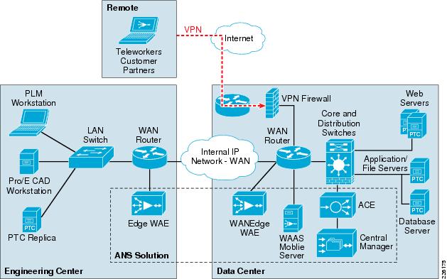
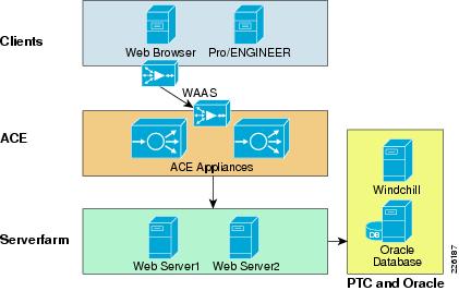
The Cisco DRD solution overview shown in Figure 1 depicts these capabilities and how they integrate to form a complete, end-to-end solution.
Figure 1 Distributed Research and Development Solution
Windchill PDMLink is configured in a standard multi-tier configuration consisting of a pair of web servers and an application server with a corresponding database server. The DRD solution did not focus on testing a fully redundant configuration. The web servers were configured in a load-balanced configuration to demonstrate the ACE load balancing capabilities during the solution testing. While a remote replication server is available for remote environments, the solution only focused on accessing content from the central data center.
Solution Architecture
Solution Framework
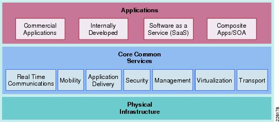
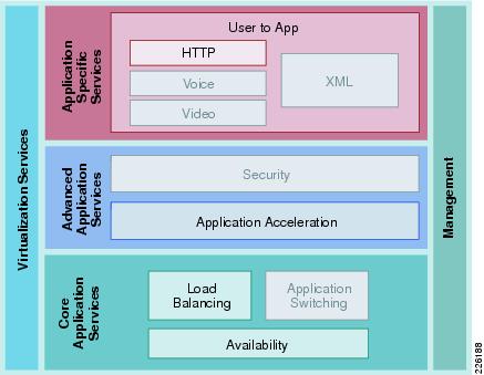
The Cisco Services-Oriented Network Architecture (SONA) framework provides a standard paradigm for designing current and next generation solutions that link network-based services with enterprise applications to drive business results. The SONA framework shown in Figure 2 illustrates the components of the solution from the infrastructure providing network-based services and the applications that use them.
Figure 2 The SONA Framework
Application Layer
The top layer of the SONA framework includes the applications that are part of the Distributed Research and Development (DRD) solution. The SONA framework identifies commercial products, applications developed internally, or sourced externally (software as a service) or a combination of types in the form of a composite, mash-up, or SOA applications. The DRD solution focuses on PLM applications that are typically commercial products versus any of the other application types. This deployment guide focuses on PTC's Windchill PDMLink and Pro/ENGINEER Wildfire applications.
Core Common Services Layer
The primary layer of the SONA framework provides common network-based services for security, mobility, real-time communications, application delivery, management, virtualization, and transport. Common services that are shared across the network increases operational efficiency and compliance requirements of the entire system. The SONA framework outlines the following services:
•
•
•
•
•
•
•
The DRD solution focuses on the use of the application delivery services to the PLM applications. The solution assumes the existence of transport (for example, WAN and LAN) and security services in the various locations and only considers how the application delivery services integrate into these functions. The solution also considers the management aspects of the application delivery services. The other services listed are not a focus or particular consideration for the solution, but may provide other value or service to the PLM applications.
Physical Infrastructure
The foundation layer of the SONA framework covers the various network locations and network resources that internal, partner, and customer users may access as part of the DRD solution. This solution uses the following places in the network (PINs), shown in Figure 3:
•
•
•
•
These PINs outline a wide variety of network infrastructure options to support a location. This solution assumes that these solutions are in place, but does not explain them in detail.
Figure 3 Places in the Network
Solution Use Cases
The solution use cases describe how the users benefit from the DRD solution. The use cases are the key scenarios where the functional requirements are defined. The DRD solution and pertinent testing to support the solution were designed around these uses cases. For this solution, PLM users and engineers or designers were simulated in two types of locations: distributed engineering centers on the enterprise WAN and remote users through a secure Internet connection.
User Types
PLM Users
PLM users rely on the product management features of the application. These users may be engineers, but may also be product managers, designers, management, or other people involved in the product lifecycle. They typically access the PTC Windchill with a web browser.
Engineers or Designers
Engineers typically use more advanced design and engineering features of the PLM solution. Pro/ENGINEER Wildfire 3 provides access to Windchill PDMLink through an embedded browser. One of the main features used involves downloading large engineering files to be worked on locally and uploading those changes when work is complete.
Locations
Distributed Engineering Centers
Since engineering centers and resources can be distributed around the globe, limited bandwidth and overall network latency may have a negative impact on application performance. The number of remote engineers also has an impact on the network and application designs.
PTC offers replication services designed to reduce the time required to upload and download files at remote locations to improve application performance for content operations that would otherwise consume bandwidth and add a significant burden of time to the end users daily responsibilities.
The focus of this solution is to improve the performance of the replication transfers and reduce the network bandwidth used by accelerating the associated traffic between the end users and the data center. PTC recommends the use of remote file servers for replication purposes for customers managing CAD data of remote sites. For customers that manage very small data sets or single files such as Microsoft office documents can use the benefits of WAAS without replication services. A remote file server reduces the overall footprint for accessing content not yet available at the remote site and reduces bandwidth consumption during application accesses, content transfers, etc.
The test results presented in this guide can also be extended to the replication services offered by PTC since the replication relies on similar protocols and requirements as the client application.
Since WAN bandwidth and latency have a significant impact on application performance, the tests were performed with different types of WAN connectivity for the distributed engineering centers.
The size of the engineering center impacts the decision to deploy a key component of the solution, the Cisco WAAS platform. That decision is typically based on the following:
•
•
•
•
•
The solution recognizes that, even without the deployment of the WAAS services, the solution provides some application acceleration for small engineering centers due to the deployment of the ACE in the data center as explained in the "Testing Results and Conclusions" section.
Remote Users
While manufacturers try to concentrate users at remote engineering centers, other users may need to access the PLM applications while external to the enterprise network. These users may be home office employees, employees that are working as a contractor at a remote customer facility, or even remote contractor resources.
This solution supports accelerating the access of the PLM and engineering applications from external, Internet-based remote locations. This use case is supported by the deployment of the Cisco WAAS Mobile application. The solution assumes that the remote user has enterprise network access through a secure virtual private network (VPN) connection.
Solution Components
The DRD solution includes networking technology that takes full advantage of application delivery features to optimize the PTC applications. The main components of the DRD solution include the following:
•
•
–
–
–
•
•
•
PTC-Windchill Application Overview
The Windchill architecture is a production-proven set of integral, modular solutions for rapid distributed collaborative development of customer driven products. Windchill was the first and remains the only proven PLM solution with the purest and most sophisticated architecture that is integral, pure Internet, and interoperable.
Integral
•
•
•
Pure Internet
•
•
•
•
•
Interoperable
•
•
•
•
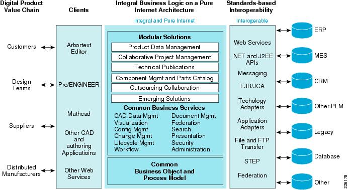
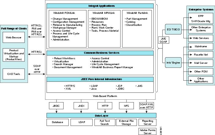
Figure 4 shows an overview of the Windchill architecture. The left-hand side of the diagram shows the various methods available for users to interact with the system. The middle portion of Figure 4 shows the foundation of the Windchill integral architecture, and the far-right side illustrates types of systems that can be easily integrated using the Windchill standards-based interoperability features.
Figure 4 Windchill Architecture Overview
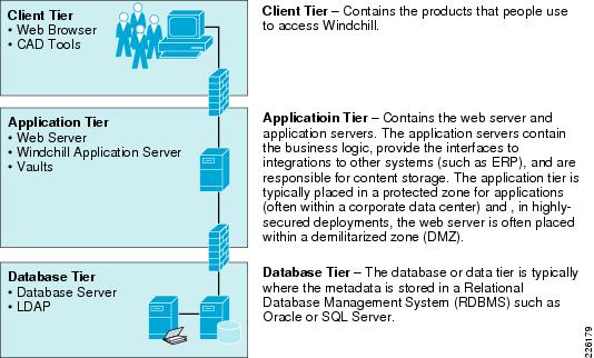
Windchill Multi-Tier Architecture
Windchill is a multi-tier architecture that can be deployed in a configuration small enough to run on a single server (for small workgroup teams), as well as in a configuration as large and complex as a highly redundant clustered system serving thousands of end users on a global scale. The architecture is commonly represented as three tiers as shown in Figure 5.
Figure 5 Windchill Multi-tier Architecture
The Windchill multi-tier architecture offers the flexibility and options to be deployed with an infrastructure that can support the most demanding distributed collaborative product development processes. This architecture can support users from various departments within the company, as well as users from supplier, manufacturing partner, and customer communities.
The core components of the Windchill runtime architecture reside in the application and database tiers:
•
•
•
•
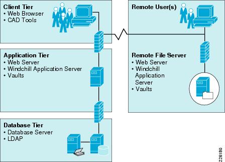
Content Storage: Remote File Servers and Replication
Customers often have users in multiple locations across the globe. To address performance concerns around uploading and downloading large amounts of content (such as CAD files) over a WAN, PTC provides the remote file server functionality. The remote file servers support the local upload and download of content at end user locations as well as the means to replicate data from location to location.
Replication is used to offset multiple downloads of the same data and reduce consumption of valuable WAN resources while providing a near LAN-like experience to the end users for content handling. This allows all users of the system to access the same information globally while maintaining the level of performance that is demanded by remote users.
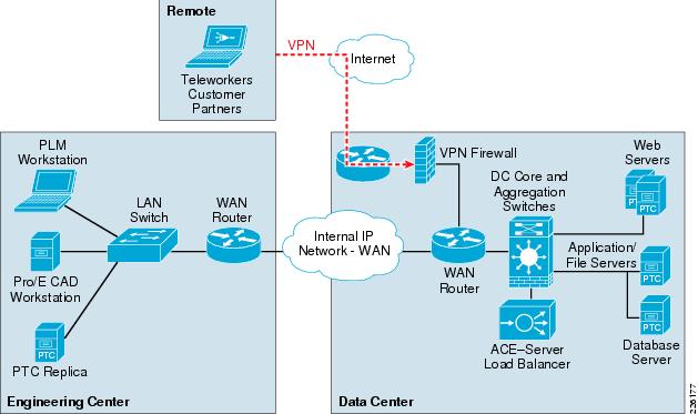
Figure 6 shows how the remote file servers are deployed at a remote location.
Figure 6 Remote Replication Servers
Pro/ENGINEER Communication Protocols
Windchill leverages web-based protocols for communication with clients. These protocols are primarily HTTP(S) over standard web ports. Clients are also able to interact with rich-client applications using RMI natively or they can be tunneled over HTTP(S). Other clients like Microsoft Office and the various Workgroup Managers support SOAP over HTTP communication with the servers.
Server-to-server and application-to-application communication uses a broader number of protocols and ports. Figure 7 illustrates the protocols and communication paths used within the Windchill architecture.
Figure 7 Protocols and Communication Paths
PTC's Windchill architecture is explained in further detail in the Windchill Architecture Overview available to current customers from PTC's Technical Support website: http://www.ptc.com/WCMS/files/83516/en/WindchillArchitectureOverview.pdf
Prospective customers may obtain a copy by contacting a local PTC sales representative.
Application Networking Services
The Cisco ANS focuses on transforming the network infrastructure to improve application performance and availability while improving security and simplifying data center and branch infrastructures. The ANS products can be grouped into two functional families: application delivery and WAN optimization.
•
•
WAAS Features and Design
Cisco WAAS is a symmetric WAN optimization and application acceleration solution designed to improve the performance of applications over a WAN. Cisco WAAS can be deployed with a hardware device called the Cisco WAE deployed in each location or as a software solution called WAAS Mobile for VPN-connected users, or both.
The WAE can be either a standalone appliance or a router-integrated network module for the Cisco Integrated Services Router (ISR). This solution focused on testing the WAE appliances, but future versions may focus on the ISR network module.
By employing these performance-improving techniques, IT organizations are able to improve productivity, minimize WAN bandwidth consumption, and enable consolidation of costly and difficult-to-manage infrastructure such as servers, storage, and data protection hardware.
Figure 8 WAAS Design
The WAAS appliance-based architecture consists of the following hardware components, as shown in Figure 8:
•
•
Cisco WAAS uses the following optimization techniques:
•
•
•
•
–
–
–
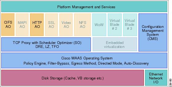
Figure 9 shows the Cisco WAAS product architecture features. The faded features provide significant benefits for many customer implementations, but were not tested in this solution.
Figure 9 WAAS Architecture
WAAS Optimization Path
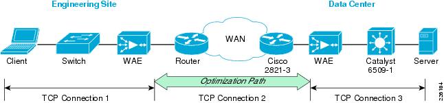
Optimizations are performed between the core and edge WAE. The WAEs act as a TCP proxy for both clients and their origin servers within the data center. Other WAN optimization solutions create optimization tunnels, and the TCP header is modified between the caching appliances. With WAAS, the TCP headers are fully preserved. Figure 10 shows the three TCP connections used by WAAS.
Figure 10 WAAS Optimization Path
The optimization path between the two WAEs is used by the WAAS to optimize the transfer of data over the WAN connection, minimizing the data sent or received. WAAS optimization mechanism such as TFO, DRE, and LZ compression are also included in the optimization path.
Cisco WAAS relies on some form of network interception to integrate into the network and receive packets from flows that are to be optimized. This design guide focuses on the following methods of network interception:
•
•
WAAS Mobile Features and Design
Cisco WAAS Mobile is a software solution that extends Cisco WAAS application acceleration benefits to any employee regardless of location. Cisco WAAS Mobile is a purpose-built, ready to use software solution consisting of client software for end users and software deployed on servers near existing VPN concentrators.
Cisco WAAS Mobile achieves industry-leading performance by extending Cisco WAAS acceleration technologies including:
•
•
•
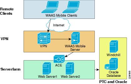
As shown in Figure 11, the Cisco WAAS Mobile software solution consists of client software for end users and server software deployed near existing VPN concentrators to extend the Cisco WAAS deployment.
Figure 11 WAAS Mobile
The client-side software is transparent and requires no user maintenance or local configuration changes:
•
•
•
•
•
The server-side software also provides an easy deployment:
•
•
•
•
•
•
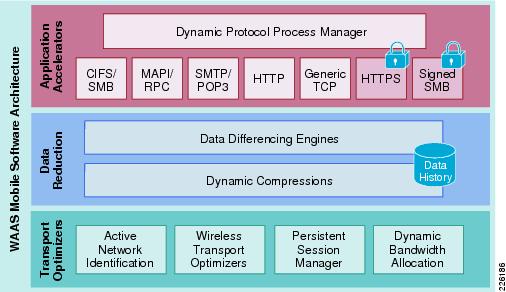
Figure 12 shows the WAAS Mobile architecture.
Figure 12 WAAS Mobile Architecture
ACE Features and Design
The Cisco ACE product family (see Figure 13), a comprehensive application delivery solution, helps ensure application availability, accelerate application performance, and protect applications while simultaneously reducing data center costs. Benefits of the Cisco ACE family products include the following:
•
•
•
•
Figure 13 ACE Design
Figure 14 shows the ACE architecture and its key features. The features that were not tested in this solution are faded out in the diagram.
Figure 14 Cisco ACE Architecture
ACE Module vs. ACE 4710 Appliance
The Cisco ACE family of products includes highly scalable modules for the Cisco Catalyst 6500 Series Switches and standalone Cisco ACE 4710 appliances. Both products offer a full range of application delivery features, including Layer 4 and Layer 7 content switching as well as a set of application acceleration capabilities.
While both offer a similar feature set, the ACE module offers the highest performance in the market and supports up to 345,000 Layer 4 connection setups and teardowns per second, while the ACE 4710 supports up to 120,000 connections per second.
The ACE 4710 appliance software used for the solution guide includes unique acceleration features not available on the ACE module:
•
•
Since this solution focused on performance optimization and not in testing a large number of sessions, the test environment relied on the Cisco ACE 4710 appliances. This also allowed for testing the unique acceleration features of the appliance.
Enterprise Data Center
The data center design is based on a proven layered model with core, distribution and access layers. The solution includes the following:
•
•
•
•
•
•
•
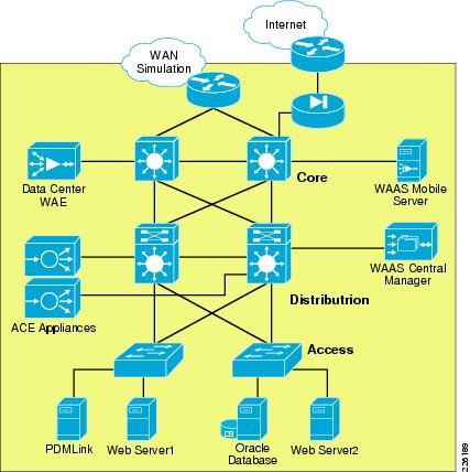
The data center architecture was not tested for this deployment guide. The application and management servers used to support PTC Windchill were incorporated in the testing of this solution. A data center environment similar to the one shown in Figure 15 was configured to demonstrate the architecture and benefits of WAAS and ACE.
Figure 15 Data Center Infrastructure
Enterprise Branch/WAN
In order to provide services to distributed engineering resources, a branch WAN solution must be in place. The enterprise branch solution outlines a wide range of networking services for branch operations, including the following:
•
•
•
•
•
•
This solution does not focus or test the following features since they are sufficiently described in other branch WAN design guides. Information on the following topics can be found at the Cisco design zone website http://www.cisco.com/go/designzone.
•
•
•
•
•
•
A Mobile/VPN Connected User
In order to provide services to mobile and single instance remote users who are not located in branch offices, a mobile VPN solution must be provided. The mobile VPN solution assumes an underlying infrastructure for VPN access into the enterprise network and the solution provides for application acceleration.
The DRD solution does not focus on or describe remote access solutions for the VPN as that topic is well covered in other guides that can be found at the Cisco design zone website http://www.cisco.com/go/designzone.
WAAS Implementation and Configuration
The following sections discuss the test configuration steps for Cisco WAAS, WAAS Mobile, and ACE used in the solution.
Implementation Overview
By default, Cisco WAAS accelerates web traffic (TCP port 80) and no additional configuration is required on the Cisco WAE to support PTC applications, unless other ports are required that are not part of the default application profile. TFO, DRE, and LZ compression are also enabled by default. Since Cisco WAAS deployments are transparent to the network, applications do not need to be aware of the added functionality and will benefit from the optimization provided by the Cisco WAEs.
Network Topology
The test environment contained one Cisco WAAS Central Manager and two Cisco WAEs managed by the WAAS Central Manager. The remote WAE was configured with a Cisco inline network adapter card and was deployed inline between the WAN router and the PTC clients or servers. The WAAS Central Manager runs on a dedicated appliance, located in the data center distribution switches, but can also be located at any layer, as long as it is able to reach the WAEs.
The following characteristics apply to WAAS deployment scenarios:
•
•
•
•
Cisco WAAS technologies require the interception of application traffic to produce results. Cisco routers support the following methods of traffic interception:
•
•
•
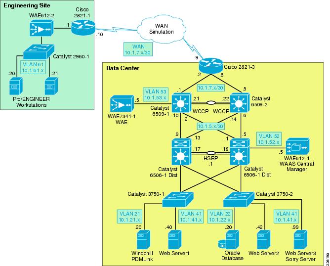
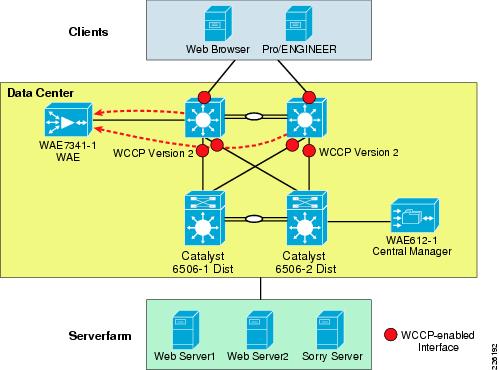
As shown in Figure 16, WCCP interception is configured on the data center Core Catalyst 6500 switches. These switches support redirection in hardware and they provide higher performance and redundancy over the single WAN edge router in the topology. While WCCP is also supported by the engineering site router, WCCP interception is not required since the WAE is deployed inline, offering an easier deployment.
Figure 16 WAAS Topology
WCCPv2 is the preferred mechanism for interception and redirection in networks that use WAAS for acceleration. PBR is usually recommended in branch deployments that cannot deploy WCCP for any reasons, which may include hardware or IOS versions deployed that do not support WCCPv2. WCCP is also preferred for the following reasons:
•
•
By default, WCCP redirects all traffic to the WAEs for inspection and optimization, unless an access list (ACL) is configured. Using WCCP ACL redirection may be beneficial for conserving WAAS processing, since it offloads the WAEs for inspecting pass-through traffic.
The following Enterprise Branch Wide Area Application Services Design Guide provides detailed design and deployment guidelines: http://www.cisco.com/en/US/docs/solutions/Enterprise/Data_Center/WAASDC11.html
Scalability and Capacity Planning
Several factors play a role when selecting the proper WAE hardware model. For the branch, the number of estimated simultaneous TCP/CIFS connections, the estimated disk size for files to be cached, and the estimated WAN bandwidth are important. Cisco provides a WAAS sizing tool for guidance; Table 2 shows a sample of the sizing information for WAEs.
High Availability
The WAEs offer many built-in high-availability features. It is recommended to configure the disk subsystem with RAID 1 protection. RAID 1 is mandatory when two or more drives are installed in a WAE, so failure of a physical drive does not affect normal operations. Multiple network interfaces are also available, providing interface failover. When connected to separate switches in active/standby mode, the standby interface protects the WAE from switch failure.
WCCP provides load-balancing and high availability through a built-in load-balancing mechanism that distributes load amongst WAEs within a service group. The WCCP protocol can have up to 32 routers and 32 devices (WAEs) per service group.
Since Cisco WAAS deployments are transparent to the application, the PTC client and servers are not aware that the Cisco WAAS is optimizing traffic flows. High availability is built into the WCCP interception. If a WAE fails or WCCP is not active, traffic flows will continue to operate without being optimized.
Inline deployments allow the WAE to be physically inserted between two network devices such as the branch switch and the branch WAN router. The Cisco WAAS inline card has four 10/100/1000BaseT Ethernet ports in two port groups. Each port group provides a fail-to-wire bypass service with mechanical relays to ensure that network connectivity is not interrupted should a device fail or a software crash be encountered by the WAE.
Configuration Task Lists
Central Manager
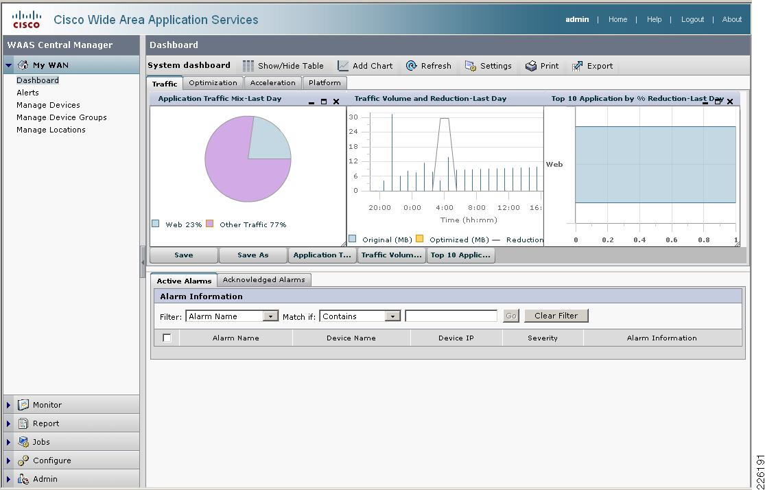
The Central Manager is the main management component of the Cisco WAAS solution. It provides a GUI interface for configuration, monitoring, and management of the branch and data center WAEs. WAEs need to contact the CM during the initial setup. This registration process adds the WAEs to the CM and initializes the local WAE database.
The Central Manager provides centralized reporting of the WAAS environment. Cisco WAEs also provide statistics through a local GUI or the CLI.
To configure the Central Manager, follow these steps:
Step 1
interface GigabitEthernet 1/0ip address 10.1.52.5 255.255.255.0!ip default-gateway 10.1.52.1Step 2
!device mode central-managerStep 3
!primary-interface GigabitEthernet 1/0Step 4
ntp server 10.1.6.1Step 5
!cms enableStep 6
Figure 17 shows the initial CM screen with an overview of the system.
Figure 17 WAAS Central Manager
Data Center WCCP Interception
In the test environment, WCCP interception was used at the data center. In data center environments, WCCP should be deployed on platforms that support redirection hardware to handle the high data rates from flow aggregation. To configure basic WCCP, the WCCP service must be enabled on at least one router and the WAEs.
The key points of this deployment model include:
•
•
•
WCCP Version 2 must be used instead of WCCP Version 1, because WCCP Version 1 only supports web traffic (port 80). In the test environment, WCCP Version 2 was enabled on the core switches and the data center WAE, as shown in Figure 18. A redundant WAE would typically be connected to the 6509-2 in the diagram.
Figure 18 WCCP Interception
Enable WCCP on the Data Center WAE
To install and configure WAE devices with WCCP, and register them with the WAAS Central Manager, follow these steps:
Step 1
!interface GigabitEthernet 1/0ip address 10.1.53.5 255.255.255.0!ip default-gateway 10.1.53.1Step 2
!primary-interface GigabitEthernet 1/0!ntp server 10.1.6.1!cms enableStep 3
!central-manager address 10.1.52.5Step 4
!device mode application-acceleratorStep 5
!wccp version 2wccp router-list 1 10.1.53.1 10.1.6.12Step 6
!wccp tcp-promiscuous router-list-num 1Enable WCCP on the Data Center Catalyst Switches
Step 1
interface Loopback1ip address 10.1.6.11 255.255.255.255Step 2
!ip wccp 61ip wccp 62Step 3
!interface GigabitEthernet2/3description to 2821-3ip address 10.1.7.1 255.255.255.252ip wccp 62 redirect inStep 4
!interface GigabitEthernet2/47description to 6506-2 Distributionip address 10.1.5.2 255.255.255.252ip wccp 61 redirect in!interface GigabitEthernet2/48description to 6506-1 Distributionip address 10.1.5.10 255.255.255.252ip wccp 61 redirect inStep 5
!interface Vlan53ip address 10.1.53.1 255.255.255.0ip wccp redirect exclude inStep 6
Remote WAE
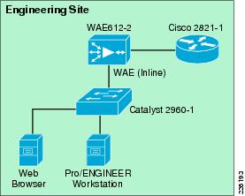
The remote engineering site does not rely on WCCP interception. Instead, a WAE Inline Network Adapter is installed. With inline interception that WAE is deployed physically between the WAN router and a switch at the remote engineering site. This allows all traffic traversing the network toward the WAN or returning from the WAN to physically pass through the WAE, giving it the opportunity to optimize traffic flows.
The Cisco PCI Inline Network Adapter provides two groups of fail-to-wire pairs, providing fail-to-wire capabilities during failure scenarios. If the WAE in Figure 19 fails, connectivity to the site would continue, but no optimization would take place.
The Cisco PCI Inline Network Adapter provides two groups of fail-to-wire pairs, providing fail-to-wire capabilities during failure scenarios. If the WAE in Figure 19 fails, connectivity to the site continues without optimization.
Figure 19 Remote Engineering Site
To configure the remote WAE for inline interception, follow these steps. No configuration changes are required to the switch or WAN router:
Step 1
!device mode application-accelerator!ntp server 10.1.6.1!ip default-gateway 10.1.61.1!central-manager address 10.1.52.5cms enableStep 2
!primary-interface InlineGroup 1/0!interface InlineGroup 1/0ip address 10.1.61.5 255.255.255.0inline vlan allexitinterface InlineGroup 1/1inline vlan allexit
HTTP Acceleration
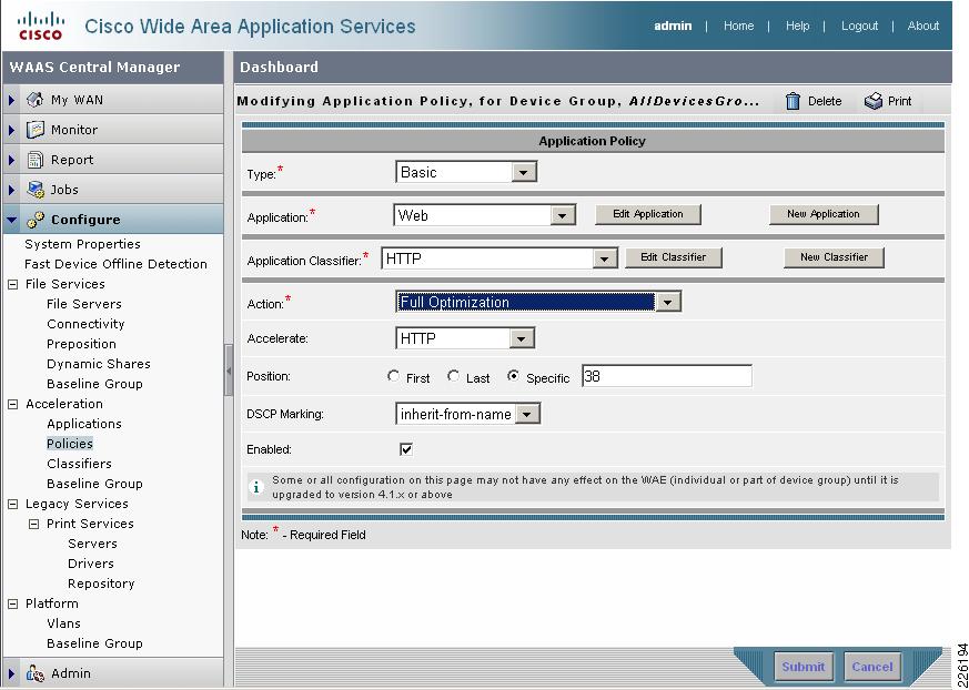
PTC's solution relies on HTTP or HTTPS traffic to communicate between the client and servers. WAAS is able to accelerate HTTP traffic on ports 80, 8080, 8000, 8001, and 3128. To verify that web application policies are in place, from the WAAS GUI, select Configure > Acceleration > Policies > HTTP. Figure 20 shows the configurations used in the test environment.
Figure 20 WAAS HTTP Policy
WAAS Implementation Caveats or Limitations
WAAS and ACE Compression
Compression should not be enabled at both WAAS and ACE when both are part of the flow. When both WAAS and ACE are part of the traffic flow, compression should only be enabled on the WAAS and disabled on the ACE. In a future release, the ACE will be able to determine what packets have already been compressed by the WAAS and disable compression for those flows. The ACE may be manually configured to disable compression.
Troubleshooting Commands
Cisco WAE Commands
The following commands may be useful when troubleshooting the WAAS configuration:
•
•
•
•
•
The following are sample outputs of some of the previous commands:
WAE612-2-EDGE#show statistics tfoTotal number of connections : 324No. of active connections : 2No. of pending (to be accepted) connections : 0No. of bypass connections : 116No. of normal closed conns : 231No. of reset connections : 91Socket write failure : 49Socket read failure : 0WAN socket close while waiting to write : 0AO socket close while waiting to write : 2WAN socket error close while waiting to read : 0AO socket error close while waiting to read : 40DRE decode failure : 0DRE encode failure : 0Connection init failure : 0WAN socket unexpected close while waiting to read : 0Exceeded maximum number of supported connections : 0Buffer allocation or manipulation failed : 0Peer received reset from end host : 0DRE connection state out of sync : 0Memory allocation failed for buffer heads : 0Unoptimized packet received on optimized side : 0Data buffer usages:Used size: 0 B, B-size: 0 B, B-num: 0Cloned size: 36757 B, B-size: 52224 B, B-num: 67Scheduler:Queue Size: IO: 0, Semi-IO: 0, Non-IO: 0WAE7341-1#show statistics dreCache:Status: Usable, Oldest Data (age): 2h18m58sTotal usable disk size: 503325 MB, Used: 0.00%Hash table RAM size: 2012 MB, Used: 0.00%Connections: Total (cumulative): 321 Active: 1Encode:Overall: msg: 8570, in: 83716 KB, out: 10982 KB, ratio: 86.88%DRE: msg: 8470, in: 83694 KB, out: 17236 KB, ratio: 79.41%DRE Bypass: msg: 4595, in: 22329 BLZ: msg: 4074, in: 9265 KB, out: 2962 KB, ratio: 68.02%LZ Bypass: msg: 4496, in: 7992 KBAvg latency: 0.327 ms Delayed msg: 17620Encode th-put: 29896 KB/sMessage size distribution:0-1K=50% 1K-5K=10% 5K-15K=12% 15K-25K=10% 25K-40K=15% >40K=1%Decode:Overall: msg: 1043, in: 187 KB, out: 665 KB, ratio: 71.86%DRE: msg: 967, in: 613 KB, out: 658 KB, ratio: 6.91%DRE Bypass: msg: 874, in: 6988 BLZ: msg: 776, in: 185 KB, out: 616 KB, ratio: 69.88%LZ Bypass: msg: 267, in: 1696 BAvg latency: 0.070 msDecode th-put: 9144 KB/sMessage size distribution:0-1K=76% 1K-5K=23% 5K-15K=0% 15K-25K=0% 25K-40K=0% >40K=0%WCCP Router Commands
•
•
•
•
The following is a sample output of the show ip wccp command executed on the 6509-1 core switch:
6509-1#show ip wccpGlobal WCCP information:Router information:Router Identifier: 10.1.6.11Protocol Version: 2.0Service Identifier: 61Number of Service Group Clients: 1Number of Service Group Routers: 1Total Packets s/w Redirected: 14065Process: 0CEF: 14065Redirect access-list: -none-Total Packets Denied Redirect: 0Total Packets Unassigned: 0Group access-list: -none-Total Messages Denied to Group: 0Total Authentication failures: 0Total Bypassed Packets Received: 0Service Identifier: 62Number of Service Group Clients: 1Number of Service Group Routers: 1Total Packets s/w Redirected: 263Process: 0CEF: 263Redirect access-list: -none-Total Packets Denied Redirect: 0Total Packets Unassigned: 87Group access-list: -none-Total Messages Denied to Group: 0Total Authentication failures: 0Total Bypassed Packets Received: 0WAAS Mobile Implementation and Configuration
Network Topology
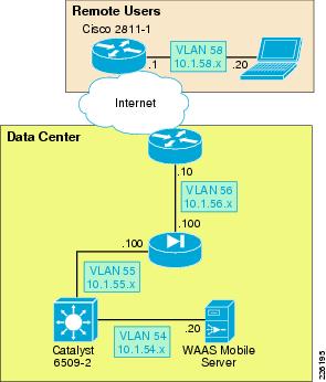
The test environment contains one WAAS Mobile server located in the data center and remote PTC clients connecting through a VPN service into a Cisco ASA appliance. The Internet connectivity is provided by a T1 connection. While several factors may impact Internet connectivity, the lab connection used 100ms delay and 1 percent packet drop to simulate a typical Internet connection. Figure 21 shows the WAAS Mobile topology.
Figure 21 WAAS Mobile Topology
WAAS Mobile Server
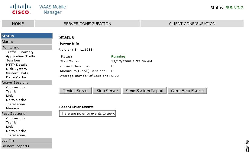
The WAAS Mobile server was installed on a Windows 2003 Enterprise server following these steps:
Step 1
Step 2
Step 3
Step 4
Step 5
Step 6
Figure 22 WAAS Mobile Manager Server
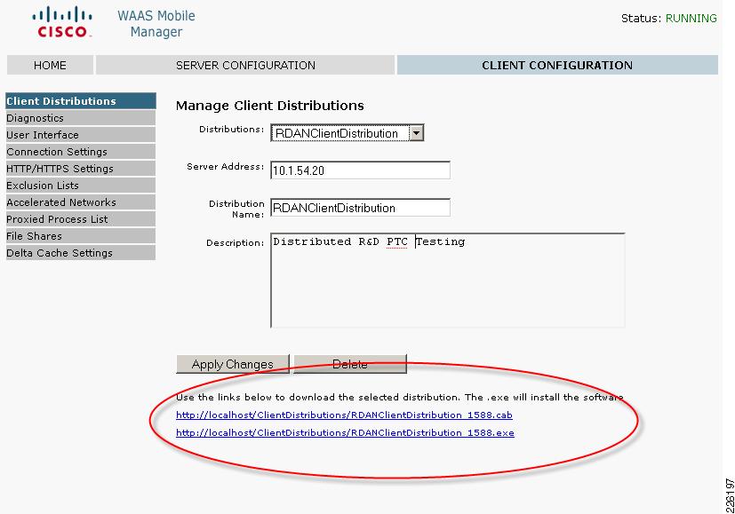
Create a Client Distribution
Step 1
Step 2
Step 3
Step 4
Figure 23 WAAS Mobile Client Distribution
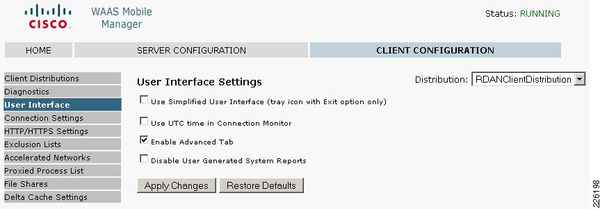
Step 5
Figure 24 WAAS Mobile Advanced Tab
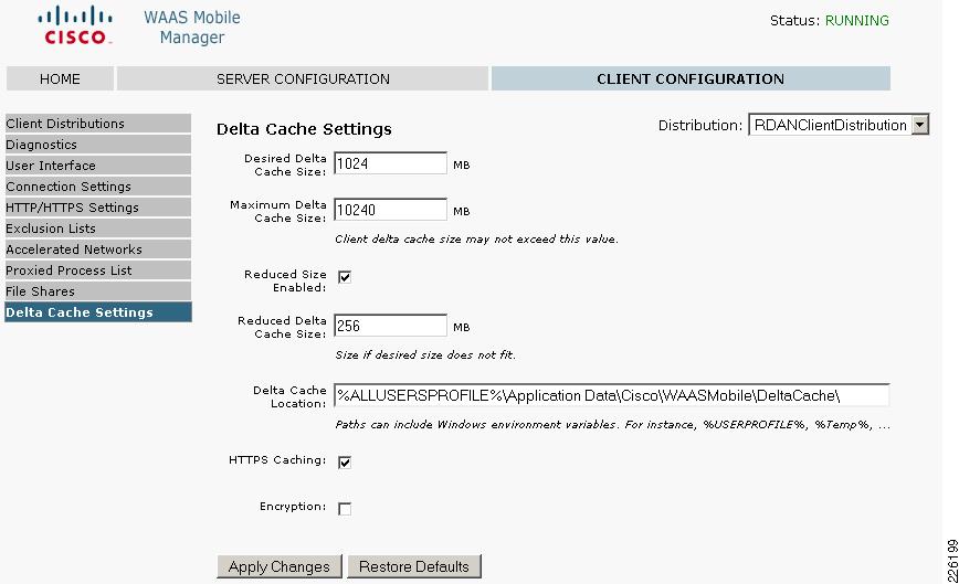
Figure 25 shows the Delta Cache Settings configured for the user, with a 1GB local cache and the file location.
Figure 25 Delta Cache Settings
WAAS Mobile Configuration for Pro/ENGINEER
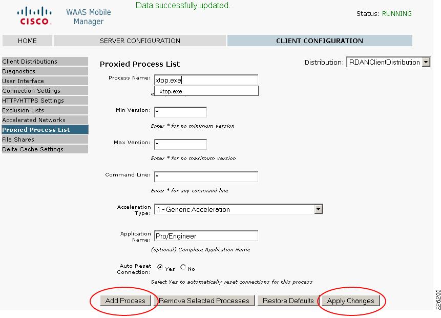
While Cisco WAAS acts on TCP connections in general, Cisco WAAS Mobile acts on individual well-defined applications. In order to optimize Pro/ENGINEER, the application must be added to the Proxied Process List in the Cisco WAAS Mobile Manager.
Figure 26 shows the steps to add Pro/ENGINEER to the proxied list. Under Client Configuration > Proxied Process List, enter the following:
•
•
•
Note
Figure 26 Proxied Process List
WAAS Mobile Client Installation
To install the WAAS Mobile client, follow these steps:
Step 1
Step 2
Step 3
Step 4
icon will appear in the Windows System Tray and turn green.
The following icons are displayed in the Windows System Tray of the client PC to indicate the status of WAAS Mobile:
Connected—WAAS Mobile is accelerating applications
User Disabled—Application acceleration disabled by the user
Persistent Connection—The client lost connection to the WAAS Mobile server but acceleration session is still active
Not Connected —The client lost connection to the WAAS Mobile server and is not accelerating applications. This is also displayed when the client is connected to a high-speed network
Client Software Configuration
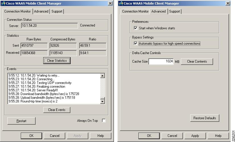
The client configuration can be easily managed from the central WAAS Mobile server, while the client has limited configuration options. Figure 27 shows the WAAS Client Manager displaying connection statistics and the optional Advanced tab allowing the client to change delta cache and startup settings.
Figure 27 WAAS Mobile Client Manager
Cisco ASA Configuration
The ASA was configured to support remote VPN user connections. "Appendix C—Device Configurations" section shows the ASA detailed configuration.
Cisco VPN Client
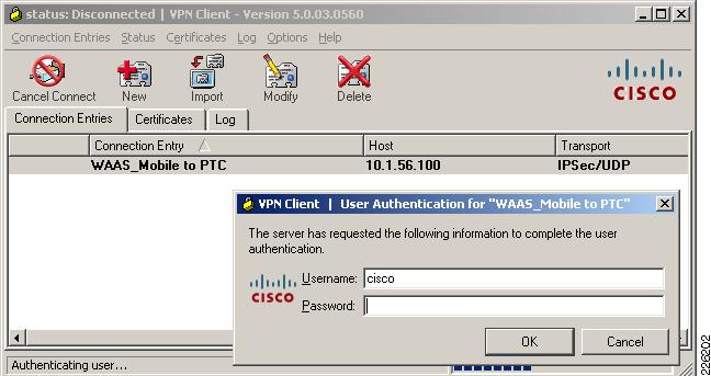
In order to connect securely to the data center ASA, a VPN connection is established using the Cisco VPN client. For the test environment, local authentication was used to authenticate the user.
Figure 28 shows a client connection to the outside interface of the ASA on IP address 10.1.56.100.
Figure 28 Cisco VPN Client
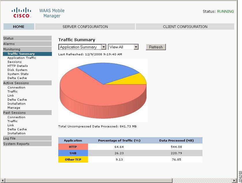
System Reports
The WAAS Mobile Manager provides valuable reports to determine the acceleration benefits for an application. Figure 29 shows a sample report describing the traffic summary for different applications and details on how much traffic was processed.
Figure 29 WAAS Mobile Manager
ACE Implementation and Configuration
The Cisco ACE 4710 appliance was configured in bridged mode, with both the client-side and server-side VLANs on the same subnet. Two ACE 4710 appliances were configured in fault-tolerant mode to ensure that network services and applications are always available. The following features were implemented:
•
•
•
•
•
•
•
•
•
A web serverfarm was configured with two servers responding to user requests. The Cisco ACE was configured to provide load balancing between the servers and the remote PTC users. In case the servers were offline or unable to respond to users requests, a third server (sorry server) was configured to make users aware of the service disruption.
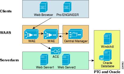
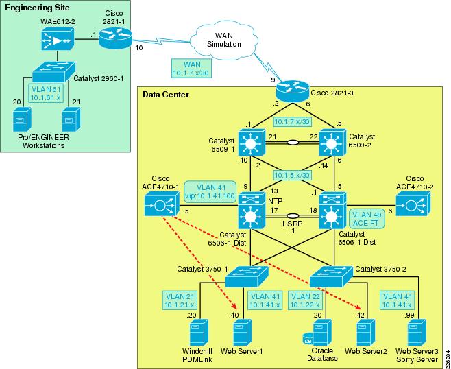
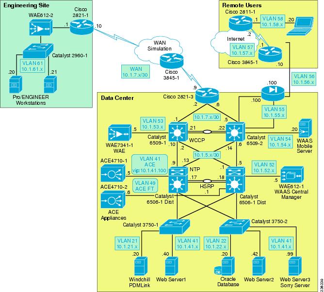
Network Topology
The Cisco ACE appliance uses a range of Cisco application switching technologies, such as Layer 4 load balancing, Layer 7 content switching, caching and TCP processing. The Cisco ACE is deployed in the distribution layer, in front of a web serverfarm supporting the PTC application and Oracle database. As shown in Figure 30, PTC clients reach the ACE through a single virtual IP (VIP) address (at 10.1.41.100) before reaching a server selected by the ACE. In turn, the ACE selects the best web server to service the request.
Figure 30 ACE Network Topology
Features and Design Considerations
PTC offers a flexible environment supporting a large number of application servers. The web servers provide clients with access to the PTC applications without directing access to a PTC application server or database directly. A web serverfarm allows the PTC to support a large number of users while providing redundancy and high availability. The web serverfarm allows for the application to be operational while servers are shutdown for maintenance or updates. The configuration used for the testing only employed a load balanced web-tier for simplicity. The Windchill architecture also allows for clustered application servers and database tiers.
High Availability and Load Balancing Features
For meeting high availability requirements, the Cisco ACE supports the configuration of two ACE appliances in redundant or fault tolerant mode. These appliances are connected to different Cisco Catalyst switches to provide services even if one of the appliances becomes unresponsive. Redundancy is only supported between ACE devices of the same type running the same software release.
By load balancing multiple servers in the serverfarm, the system is able to offer higher availability and scalability. This functionality can be extended to multiple serverfarms, such as PTC Windchill servers, web servers or database servers.
The Cisco ACE provides the following key functions:
•
•
•
•
Note
Configuration Task Lists
Catalyst 6500
The ACE 4710 appliances are connected to the Cisco Catalyst 6500 switches in the distribution layer, which provide two main VLANs for connectivity. VLAN 41 is dedicated to the ACE virtual IP address (10.1.41.100) and VLAN 49 is dedicated for redundancy with the backup ACE 4710 appliance. The Catalyst 6500 provides HSRP first-hop redundancy, with the 6506-1 being the active HSRP.
!vlan 41name ACE_Server_Side!vlan 49name ACE__FTAs shown in Figure 31, the connection between the Catalyst 6500 and the ACE 4710 is configured as a trunk and as an EtherChannel, allowing up to four 1Gbps interfaces to be active at the same time.
Figure 31 ACE Connections to Catalyst 6500
interface Port-channel1description ACE4710-1switchportswitchport access vlan 41switchport trunk encapsulation dot1qswitchport trunk native vlan 41switchport mode trunk!interface GigabitEthernet1/4description ACE4710-1switchportswitchport access vlan 41switchport trunk encapsulation dot1qswitchport trunk native vlan 41switchport mode trunkspeed 1000duplex fullchannel-group 1 mode on!interface GigabitEthernet1/5description ACE4710-1switchportswitchport access vlan 41switchport trunk encapsulation dot1qswitchport trunk native vlan 41switchport mode trunkspeed 1000duplex fullchannel-group 1 mode on!interface GigabitEthernet1/6description ACE4710-1switchportswitchport access vlan 41switchport trunk encapsulation dot1qswitchport trunk native vlan 41switchport mode trunkspeed 1000duplex fullchannel-group 1 mode onRemote Management Access
By default, the ACE blocks all types of network management access. In order to allow protocols such as Telnet, HTTP, HTTPS or ICMP, a policy that allows network management protocols must be configured and applied to the proper interface.
Step 1
class-map type management match-any REMOTE_ACCESSdescription Remote access traffic match2 match protocol telnet any3 match protocol ssh any4 match protocol icmp any5 match protocol http any6 match protocol https anyStep 2
policy-map type management first-match REMOTE_MGMT_ALLOW_POLICYclass REMOTE_ACCESSpermitStep 3
interface vlan 41description Server-Side interfaceservice-policy input REMOTE_MGMT_ALLOW_POLICYinterface vlan 411description Client-Side interfaceservice-policy input REMOTE_MGMT_ALLOW_POLICY
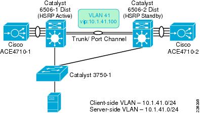
Interfaces and Default Gateway
As shown in Figure 32, the ACE appliances are connected to different Catalyst 6500 for redundancy. A trunk is configured between the Catalyst switches and the ACE allowing all VLANs, while a port channel is used to aggregate four ACE 1Gbps interfaces into the Catalyst 6500.
Figure 32 Interfaces and Default Gateway
The ACE was deployed in Layer 2 (bridged) mode, bridging VLAN 41 and VLAN 411. VLAN 411 acts as the client -side VLAN and VLAN 41 as the server-side VLAN.
An access list named ALL is used to permit or deny traffic through the interfaces as shown in the following example:
access-list ALL line 8 extended permit ip any anyaccess-list ALL line 20 extended permit icmp any anyinterface vlan 41description Server-Side interfacebridge-group 10access-group input ALLservice-policy input REMOTE_MGMT_ALLOW_POLICYno shutdowninterface vlan 411description Client-Side interfacebridge-group 10access-group input ALLaccess-group output ALLservice-policy input REMOTE_MGMT_ALLOW_POLICYno shutdownIn bridged mode, an interface BVI is required to merge both client- and server-side VLANS as shown below:
interface bvi 10ip address 10.1.41.5 255.255.255.0no shutdownThe Catalyst 6500 has interfaces defined for these VLANS and acts as the HSRP group for VLAN 411. All servers point to 10.1.41.1, the HSRP address for their default gateway. In this case, 6506-1 acts as the primary router:
On 6506-1 On 6501-2interface Vlan411 interface Vlan411ip address 10.1.41.2 255.255.255.0 ip address 10.1.41.3 255.255.255.0standby 41 ip 10.1.41.1 standby 41 ip 10.1.41.1standby 41 priority 110 standby 41 priority 90standby 41 preempt standby 41 preemptFlows initiated from the servers require an inbound access list to allow the flow on the interface where the request is received.
•
•
•
At a minimum, an ACL is required on the server-side VLAN to allow for server-initiated flows:
!access-list ALL line 8 extended permit ip any any!interface vlan 41description Server-Side interfacebridge-group 10access-group input ALLRedundant ACE Appliances
Redundancy is configured with a maximum of two ACE appliances; the appliances must be of the same ACE type and software release. Redundancy provides a seamless switchover of flows in case an ACE becomes unresponsive or a critical host, interface or HSRP group fails.
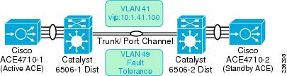
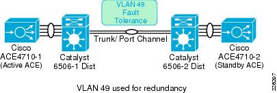
Each appliance contains one or more fault-tolerant (FT) groups and each group consists of two members: one active and one in standby. A dedicated FT VLAN is used between the ACEs to transmit flow-state information and the redundancy heartbeat. This VLAN should not be used for normal network traffic. As shown in Figure 33, VLAN 49 is configured as the FT VLAN.
Figure 33 Redundant ACE Appliances
The following commands are required to enable redundancy at the ACE appliances:
!ft interface vlan 49ip address 10.1.49.1 255.255.255.0peer ip address 10.1.49.2 255.255.255.0!ft peer 1heartbeat interval 300heartbeat count 10ft-interface vlan 49!ft group 2peer 1priority 110peer priority 105associate-context AdmininserviceThe show ft groups status command is used to verify that redundancy is enabled:
ACE4710-1/Admin# show ft group statusFT Group : 2Configured Status : in-serviceMaintenance mode : MAINT_MODE_OFFMy State : FSM_FT_STATE_ACTIVEPeer State : FSM_FT_STATE_STANDBY_HOTPeer Id : 1No. of Contexts : 1Real Server and Serverfarm
Real servers are dedicated physical servers configured in groups called serverfarms. Three web servers were configured to provide PTC services. These real servers are used by the ACE to send intended traffic based on certain criteria, while a sorry server was configured to alert users of any service disruptions.
The following configurations show the three real servers with their respective IP addresses.
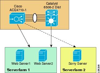
server host SERVER1description Web_Server_1ip address 10.1.41.40inservicerserver host SERVER2description Web_Server_2ip address 10.1.41.42inservicerserver redirect SORRY_SERVERwebhost-redirection http://10.1.41.99/inserviceA serverfarm is a logical collection of real servers that the ACE selects based on certain sets of criteria. Serverfarms contain the same content and typically reside in the same physical location in a data center. The two web servers in Serverfarm 1 (see Figure 34) serve requests from PTC clients, while the sorry server is accessed only when the servers in Serverfarm 1 are not available.
Figure 34 Serverfarms
The following configuration shows the configuration for the two servers in SFARM1 and a sorry server in SFARM2:
serverfarm host SFARM1rserver SERVER1inservicerserver SERVER2inserviceserverfarm redirect SFARM2rserver SORRY_SERVERinserviceSession Persistence (Stickiness)
Session Persistence allows multiple connections from the same client to be directed to the same real server for the duration of a session. Persistence is required by Windchill and PTC recommends the use of the HTTP cookie method as the primary type of persistence, but other forms of persistence are also expected to work. The ACE supports several sticky methods, including source and/or destination IP address, HTTP cookie, HTTP header, etc.
•
•
•
With cookie insert, the ACE inserts a cookie on behalf of the server upon the return request, even when the servers are not configured to set cookies. The cookie contains information used by the ACE to ensure persistence to a specific real server.
The following commands define the cookie insert and how they are applied to the proper policy map:
sticky http-cookie ACE_COOKIE C-STICKYcookie insert browser-expireserverfarm SFARM1 backup SFARM2policy-map type loadbalance first-match L7_VIP_POLICYclass class-defaultsticky-serverfarm C-STICKYHealth Monitoring
The ACE is able to monitor the state of a server by sending out probes. The ACE verifies the server response and checks for any network problems that can prevent a client to reach a server. Based on the server response, the ACE can place the server in or out of service, and can make reliable load-balancing decisions. The ACE supports 1,000 unique probe configurations, including ICMP, HTTP and other predefined health probes.
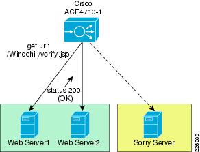
The HTTP probe issues an HTTP request to the server for an expected string and status code. The ACE then compares the received response, looking for a string in the received page. If the request fails, the server is marked as failed. Figure 35 shows the probe interaction between the ACE and the web servers.
Figure 35 Health Monitoring
For the test environment, an HTTP probe was used. The probe is configured to access the /Windchill/verify.jsp page and expects a status 200 (OK). The probe is then applied to the serverfarm. The default installation of Windchill does not include the verify.jsp page used in the testing, but can be obtained by contacting PTC Technical Support. The page that is accessed by the probe must be in an anonymously accessible location on the web server.
In the following example, using the interval parameter, a probe is sent every 30 seconds to the server. Before the ACE marks a server as failed, it must detect that probes have failed a consecutive number of times. By default when three consecutive probes have failed the ace marks the server as failed. In the lab configuration the faildetect parameter was set to two retries.
After the ACE marks a server as failed, it waits a period of time and then sends the probe to the failed server. When a number of consecutive successful probes are received the server is marked as passed. In the lab configuration, failed servers were probed every 30 seconds using the passdetect interval command, and three successful probe responses were required before the server was brought back into the serverfarm.
http HTTPPROBEinterval 30faildetect 2passdetect interval 30passdetect count 3request method get url /Windchill/verify.jspexpect status 200 200open 1!serverfarm host SFARM1probe HTTPPROBErserver SERVER1inservicerserver SERVER2inserviceLayer 7 Load Balancing
Cisco ACE supports both Layer 4 and Layer 7 load balancing. Layer 7 load balancing is deployed in this environment since features such as cookie sticky are enabled. Cisco ACE uses class-map, policy-map, and service-policies to classify and take action on incoming user requests.
For the test environment, the following steps were used to configure load balancing:
Step 1
class-map match-all L4_VIP_ADDRESS_CLASS2 match virtual-address 10.1.41.100 tcp eq wwwStep 2
class-map type http loadbalance match-any OBJECTS3 match http url .*css5 match http url .*class6 match http url .*jar7 match http url .*cab8 match http url .*txt9 match http url .*ps10 match http url .*vbs11 match http url .*xsl12 match http url .*xml13 match http url .*pdfb14 match http url .*swf22 match http url .*jpg23 match http url .*jpeg24 match http url .*jpe25 match http url .*png26 match http url .*gifStep 3
parameter-map type optimization http EXPIRESexpires-setting time-to-live 3600Define a policy-map of type loadbalance to associate the server farm:policy-map type loadbalance first-match L7_VIP_POLICYclass class-defaultsticky-serverfarm C-STICKYStep 4
policy-map multi-match L4_VIP_POLICYclass L4_VIP_ADDRESS_CLASSloadbalance vip inserviceloadbalance policy L7_VIP_POLICYloadbalance vip icmp-replyStep 5
interface vlan 411description Client-Side interfacebridge-group 10access-group input ALLaccess-group output ALLservice-policy input L4_VIP_POLICY
ACE Compression
The ACE supports compressing packets to improve site performance and to offload the compression work from the web servers or clients. By performing compression on the ACE, the servers can provide other services to clients and provide faster response times. By default, ACE compression is disabled. When compression is enabled, the appliance compresses data in the HTTP GET or POST responses from the real servers. The ACE does not compress HTTP requests from clients or the HTTP headers in the server responses.
PTC's default configuration for the Apache web server enables web server compression for HTML/TXT content only. Other mime types are not included by default. Web server compression can be completely disabled and offloaded to the ACE. To enable compression on the ACE follow these steps:
Step 1
policy-map type loadbalance first-match L7_VIP_POLICYclass class-defaultcompress default-method gzipStep 2
parameter-map type http HTTP_COMPRESSIONpersistence-rebalancecompress minimum-size 1024compress mimetype "text/.*"compress mimetype "application/pdf"compress mimetype "application/javascript"compress mimetype "application/msword"Step 3
policy-map multi-match L4_VIP_POLICYclass L4_VIP_ADDRESS_CLASSappl-parameter http advanced-options HTTP_COMPRESSIONFlashForward Acceleration
The goal of FlashForward is to eliminate the network delays associated with embedded web objects, such as images, style sheets, etc. FlashForward combines the local object storage with dynamic renaming of embedded objects to enforce object freshness within the parent HTML page.
Without FlashForward, the user experiences delays when pages with graphic images load because each object requires validation to ensure that the user has the latest version. Each validation involves an HTTP request from the client to the server, but FlashForward guarantees that clients request only the latest objects and never issue validation requests for objects in the browser cache that the ACE has determined to be valid.
FlashForward places the responsibility for validating object freshness on the ACE rather than on the client, making the process more efficient.
To configure FlashForward on the test environment, the following commands were configured:
Step 1
class-map type http loadbalance match-any OBJECTS3 match http url .*css5 match http url .*class6 match http url .*jar7 match http url .*cab8 match http url .*txt9 match http url .*ps10 match http url .*vbs11 match http url .*xsl12 match http url .*xml13 match http url .*pdfb14 match http url .*swf22 match http url .*jpg23 match http url .*jpeg24 match http url .*jpe25 match http url .*png26 match http url .*gifclass-map type http loadbalance match-all PAGE2 match http url .*Step 2
policy-map type optimization http first-match OPTIMIZERclass OBJECTSaction OBJECTS parameter EXPIRESclass PAGEaction PAGEStep 3
action-list type optimization http OBJECTSflashforward-objectaction-list type optimization http PAGEflashforwardStep 4
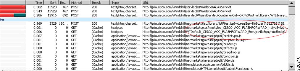
policy-map multi-match L4_VIP_POLICYclass L4_VIP_ADDRESS_CLASSoptimize http policy OPTIMIZERPacket capture tools such as HTTPWatch or FireBug can be used to verify FlashForward optimization. On a first visit to the web servers, all objects are served from the server, with at response of 200 OK. Once the ACE cache has been populated, the PTC client browser will also download the FlashForward embedded objects referenced in the HTML container page. The HTTPWatch capture in Figure 36 shows that the HTML source of the container page has been modified by changing the embedded object URL:
Figure 36 FlashForward Capture
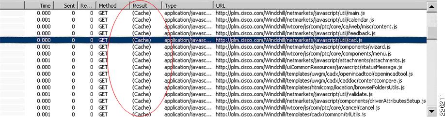
On a repeat visit, the browser should not validate objects in its cache, therefore response time is improved and the number of requests to build a page is reduced. FlashForward objects are served from the local browser's cache, as opposed to the web server. A new capture should show that only a few client requests are made to the web server and that most content is served from the browser's cache. The number of 304 responses (Not Modified) should also be reduced. Figure 37 shows a capture with all requests being served from the local browser's cache.
Figure 37 FlashForward Optimization
ACE Implementation Caveats or Limitations
WAAS and ACE Compression
During testing, it was determined that compression should not be enabled at both WAAS and ACE when both are part of the traffic flow. When both WAAS and ACE are part of the traffic flow compression, should be enabled on the WAAS and disabled on the ACE. In a future release, the ACE will be able to determine what packets have already been compressed by the WAAS and disable compression for those flows. With the tested software releases, a manual configuration must take place for specific flows.
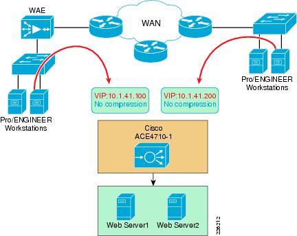
ACE Compression still provides valuable performance improvements for remote sites that do not have WAAS deployed. A simple way to do this is to create a separate VIP address for sites that want to benefit from ACE compression but have not deployed WAAS, as shown in Figure 38.
Figure 38 ACE and WAAS Compression
FlashForward
The benefits of FlashForward are more apparent on applications that contain objects embedded within HTML pages or pages with graphic objects that can be served from a local browser. PTC Windchill provides a very dynamic environment and many pages are created dynamically.
While FlashForward is able to accelerate applications and reduce requests to the server, the results did not show an overall improvement for PTC Windchill within the lab testing environment. PTC has customers that have implemented a similar equivalent to FlashForward within their web server configuration to address these performance concerns and have seen significant improvements in cached object verifications. It is anticipated that the use of FlashForward will provide benefits for users that may experience these issues and be transparent for users that would not notice under their working conditions, but the lab testing did not provide the opportunity to calculate the benefits of using FlashForward, since a full regression test was not performed to identify other areas that may impact PTC applications.
During testing, an issue with FlashForward was found and bug CSCsu90166 was filed. The bug showed the ACE leaving client connections open and, therefore, blocking subsequent file uploads until a timeout occurred. This bug only has an impact when WAAS and ACE are enabled.
Until the bug is fixed, the following workarounds should be considered:
•
•
interface vlan 41description Server-Side interfacebridge-group 10access-group input ALLnat-pool 1 10.1.41.60 10.1.41.60 netmask 255.255.255.255 pat!policy-map multi-match L4_VIP_POLICYclass L4_VIP_ADDRESS_CLASSloadbalance vip inserviceloadbalance policy L7_VIP_POLICYnat dynamic 1 vlan 41Troubleshooting Commands
The following commands may be useful when troubleshooting the ACE configuration:
•
•
•
•
•
•
•
•
•
•
Testing Results and Conclusions
The optimization tests were performed on a full working copy of PTC Windchill, Oracle database and web servers operating on virtual machines. A full data center implementation and remote engineering site were configured to provide the proper connectivity. Cisco ACE, WAAS, and WAAS Mobile devices were also tested in different configurations to validate the optimization of PTC applications.
WAAS and WAAS Mobile optimizations are noted in the WAN as well as the end-user experience of applications. Application performance is measured depending on who is the consumer of the data. To the end user, the application response time is important, since performance is evaluated by the user experience while to the network administrator low bandwidth utilization and network performance are important.
One of the most compelling reasons to use the Cisco WAAS is to provide the user with as close to LAN-like response as possible, with the PTC application residing over the WAN in the data center. This implies that the user and application response time become critical metrics. End-to-end latency times (application client/server latency plus network latency) from the client perspective can be measured easily by capturing download times and perceived download rates.
Test Methodology
A series of test were performed to stimulate PTC Windchill and Pro/ENGINEER users during a typical working day. The following three main categories were tested:
•
•
•
Pro/ENGINEER Testing
•
•
The following three types of tests were conducted for each category:
•
(config)#interface inlinegroup 1/0(config-if)#shutdownFor the data center WAE, disable WWCP at the core switches:
(config)#no ip wccp 61(config)#no ip wccp 62•
•
Additional tests were performed to focus on compression, window sizing, and acceleration features. Optimization with SSL traffic is planned for a future release of this deployment guide.
Application Test Results
The PTC Windchill PDMLink tests were performed using Internet Explorer and HTTPWatch for data collection. The purpose of the test was to stimulate a typical PTC environment, with remote users dispersed throughout the world and the PTC application deployed in a centralized data center.
Note
Table 3 represents a summary of the results obtained for each group of PTC operations. The summary was collected from WAAS and WAAS Mobile over a T-1, 100ms delay. Each result represents numerous combinations of tests. Detailed charts are presented in the next few sections.
WAN Simulation
For WAAS testing, two different bandwidth speeds were used during testing, each one with different latency and drop capabilities (see Table 4). The purpose was to stimulate a typical intra-continental circuit and a slower intercontinental circuit.
Table 4 WAN Simulation Speeds
Intra-continental
T1
100ms
1%
Inter-continental
T1
400ms
1%
For WAAS Mobile testing, a T-1 connection with 100ms latency and 1 percent packet loss was used to simulate a typical Internet connection. It should be noted that remote access network characteristics vary widely depending on the type of internet connection (Wi-Fi, 3G, DSL, cable, and satellite), creating dramatic performance differences for remote users. The results in this test are indicative of a best-case Internet connection; the improvement for other connections would be even greater, as the unaccelerated test times would increase as network conditions degrade.
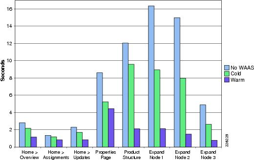
HTTP Operations—WAAS
This group of tests focused on typical user operations performed with a web browser. The optimization benefits become apparent when WAAS is part of the traffic flow. Figure 39 shows the Home Overview page for PTC Windchill.
Figure 39 PTC Windchill HTTP Operations
Table 5 shows the number of objects used for some of the HTTP operations.
Table 5 Number of Objects
Product Structure
5,218
Expand Node 1
357
Expand Node 2
544
Expand Node 3
92
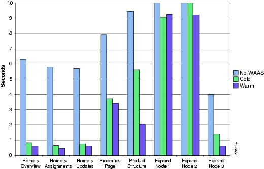
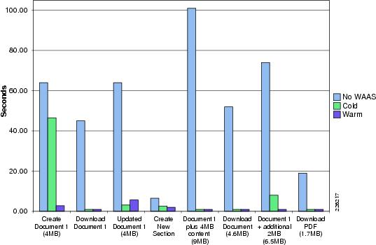
Figure 40 shows the performance over a T-1, 100ms delay while Figure 41 shows the performance over a T-1, 400ms delay.
Figure 40 HTTP Operations —T1 100ms 1% Drop
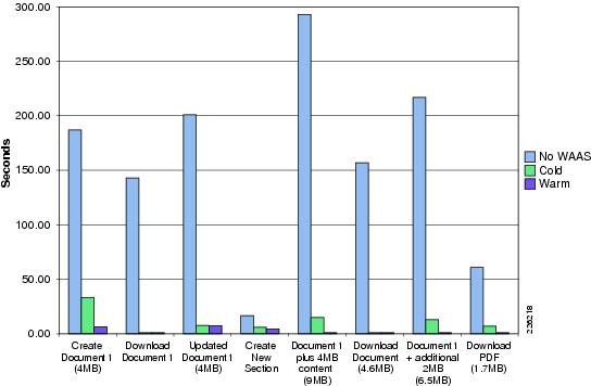
The results in Figure 41 show the impact that WAAS has on a T1 400ms, and shows that the warm results are very similar to a T-1 100ms delay.
Figure 41 HTTP Operations - T1 400ms 1% Drop
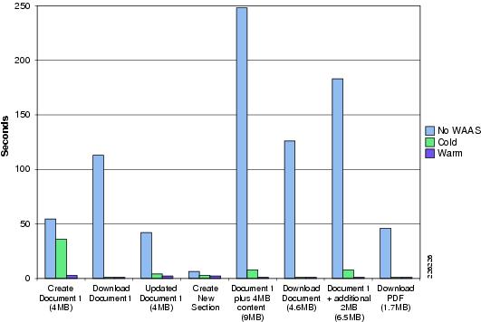
HTTP Content Operations—WAAS
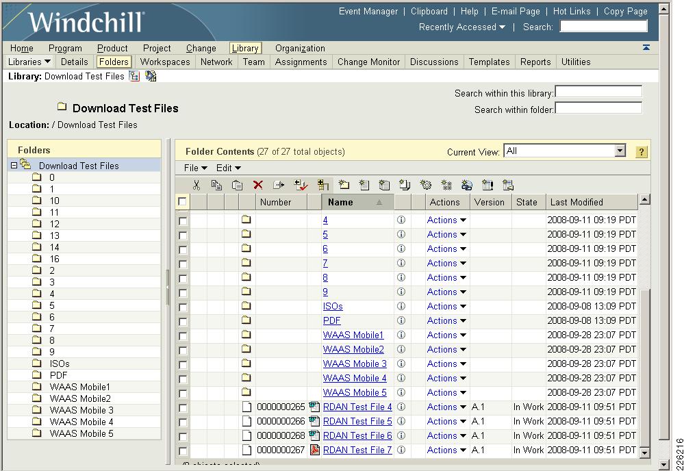
Typical file upload/download operations can benefit from application acceleration, particularly large CAD files. Once a file has been transferred once, WAAS is able to identify any portion of the document and only transfer the portions of the document that have been updated or modified. Figure 42 shows the Library > Folders screen used in the test environment.
Figure 42 PTC Windchill Content Operations
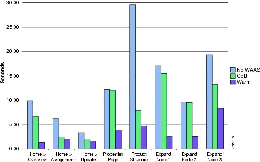
The following test results include creating a document and making updates to the different sections of the document. Figure 43 and Figure 44 show details for different T-1 configurations.
Figure 43 HTTP Operations - T1 100ms 1% Drop
Figure 44 HTTP Operations - T1 400ms 1% Drop
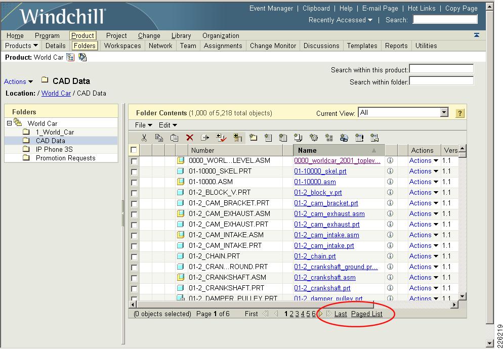
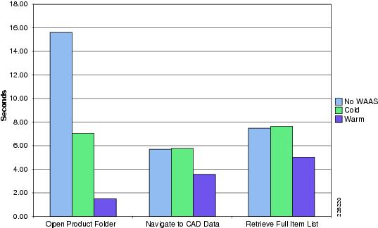
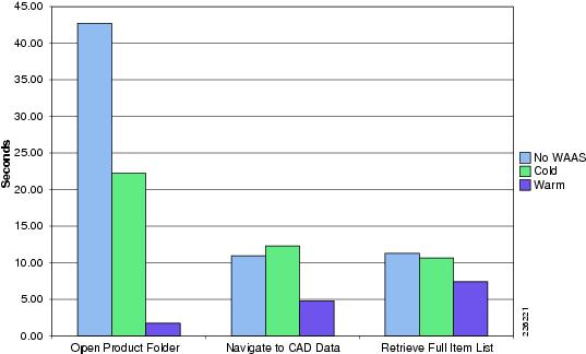
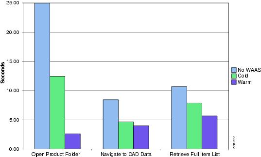
Folder Browsing Operations —WAAS
The following tests focus on capturing the time that it takes to retrieve folder lists from the server. This function can be slow since all data is retrieved from the origin server. By default, only 200 items are displayed on a page, but selecting "Full List" retrieves the complete list of items from the server (5,218 total objects).
Figure 45 shows the folders used in the test environment and how to select the Paged List or Full List of objects.
Figure 45 PTC Windchill - Folder Operations
The test results in Figure 46 and Figure 47 show the results from different T-1 configurations.
Figure 46 Folder Browsing - T1 100ms 1% Drop
Figure 47 Folder Browsing - T1 400ms 1% Drop
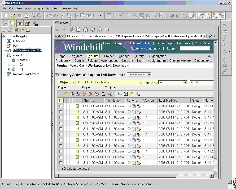
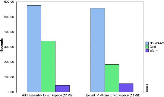
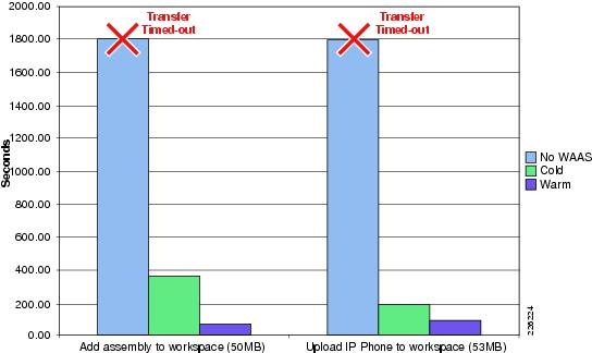
Pro/ENGINEER Testing—WAAS
The following tests show typical operations performed by Pro/ENGINEER users working with different assemblies. An Add to Workspace operation was performed for a subset of the PTC World Car assembly. A subsequent workspace operation was performed uploading a Cisco provided Pro/ENGINEER assembly for a IP Phone product design. Figure 48 shows the Pro/ENGINEER Wildfire workspace.
Figure 48 Pro/ENGINEER Workspace
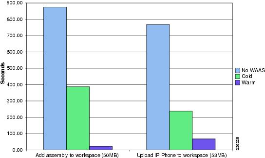
The tests results in Figure 49 show typical operations performed by Pro/ENGINEER users working with different assemblies and adding a subassembly of the world car or uploading the Cisco IP phone. The results were gathered using different T-1 configurations.
Figure 49 Pro/ENGINEER Testing - T1 100ms 1% Drop
Figure 50 shows the results for a T-1 400 ms delay. For the tests without WAAS, the transactions were unable to complete and the application timed-out after 22 minutes.
Figure 50 Pro/ENGINEER Testing - T1 400ms 1% Drop
WAAS Mobile Test Results
The WAAS Mobile tests were also grouped in typical user operations. The client workstation was configured with 1 GB of local cache, and the WAN simulation consisted of T-1 with 100ms delay and 1 percent packet drop.
The results show that WAAS Mobile also provides similar optimization to WAAS, even when the remote clients connect through the Internet and a VPN tunnel. The results should also demonstrate that users in small offices where WAAS is not deployed could also benefit from the acceleration benefits provided by WAAS Mobile.
HTTP Operations—WAAS Mobile
Figure 51 shows the results of typical user operations performed with a web browser using WAAS Mobile.
Figure 51 WAAS Mobile HTTP Operations
HTTP Content Operations—WAAS Mobile
Figure 52 shows the results of creating a document and updating different sections of it using WAAS Mobile.
Figure 52 WAAS Mobile Content Operations
Folder Operations—WAAS Mobile
Figure 53 shows the results when retrieving folder lists from the server using WAAS Mobile. This function can be slow since all data is retrieved from the origin server. By default, only 200 items are displayed on a page, but selecting Full List shows that the complete list of items contains 5,218 objects.
Figure 53 WAAS Mobile Folder Operations
Pro/ENGINEER—WAAS Mobile
Figure 54 shows typical operations performed by remote Pro/ENGINEER users working with different assemblies and adding them to the workspace.
Figure 54 WAAS Mobile Pro/ENGINEER Operations
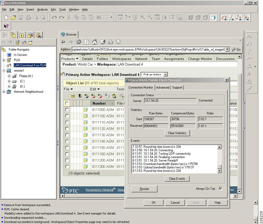
Figure 55 shows the WAAS Mobile statistics while a Pro/ENGINEER operation is taking place. The Figure 55 also shows that the client is connected to the WAAS Mobile at server at 10.1.54.20 and the current compression ratios.
Figure 55 Pro/ENGINEER and WAAS Mobile
Appendix A—Test Environment
Figure 56 Full Network Topology
Hardware and Software Releases
Table 6 lists the PTC software used in this solution.
Table 7 lists the Cisco WAAS and ACE software releases used in this solution.
Table 8 lists the Cisco Catalyst switches used in this solution.
Table 9 lists the Cisco ISR routers used in this solution.
Table 10 lists the Cisco ASA Adaptive Security Appliance used in this solution.
Table 10 Cisco ASA Adaptive Security Appliance
ASA 5540 Appliance
Data Center
8.0(3)
The following platforms are recommended for use with Cisco WAAS and the WCCP services:
•
•
•
•
•
Table 11 lists the key capabilities of each platform.
1.
–
–
–
–
–
2.
The following platforms support WCCP, but their implementation is not compatible with WAAS:
•
•
•
Appendix B—Reference Documents
•
http://www.cisco.com/en/US/docs/solutions/Enterprise/Data_Center/WAASDC11.html
•
http://www.cisco.com/en/US/docs/solutions/Enterprise/Branch/WAASBr11.html
•
•
•
http://www.cisco.com/en/US/prod/collateral/iosswrel/ps6537/ps6586/ps6660/guide_c07_458724.html
Appendix C—Device Configurations
Cisco ACE Configurations
Admin Context
Generating configuration....resource-class R1limit-resource all minimum 0.00 maximum unlimitedlimit-resource sticky minimum 10.00 maximum equal-to-minboot system image:c4710ace-mz.A3_1_0.binboot system image:c4710ace-mz.A1_8_0a.binlogin timeout 0hostname ACE4710-1interface gigabitEthernet 1/1channel-group 1no shutdowninterface gigabitEthernet 1/2speed 1000Mduplex FULLchannel-group 1no shutdowninterface gigabitEthernet 1/3speed 1000Mduplex FULLchannel-group 1no shutdowninterface gigabitEthernet 1/4speed 1000Mduplex FULLchannel-group 1no shutdowninterface port-channel 1switchport trunk native vlan 41switchport trunk allowed vlan 41-42,49,411port-channel load-balance src-dst-portno shutdownaccess-list ALL line 8 extended permit ip any anyaccess-list ALL line 20 extended permit icmp any anyoptimizedebug-level 7class-map type management match-any REMOTE_ACCESSdescription Remote access traffic match2 match protocol telnet any3 match protocol ssh any4 match protocol icmp any5 match protocol http any6 match protocol https anypolicy-map type management first-match REMOTE_MGMT_ALLOW_POLICYclass REMOTE_ACCESSpermitinterface vlan 42ip address 10.1.42.5 255.255.255.0peer ip address 10.1.42.6 255.255.255.0service-policy input REMOTE_MGMT_ALLOW_POLICYno shutdownft interface vlan 49ip address 10.1.49.1 255.255.255.0peer ip address 10.1.49.2 255.255.255.0no shutdownft peer 1heartbeat interval 300heartbeat count 10ft-interface vlan 49ft group 2peer 1priority 110peer priority 105associate-context Admininserviceip route 0.0.0.0 0.0.0.0 10.1.42.1context PLMallocate-interface vlan 41allocate-interface vlan 411member R1ft group 3peer 1priority 110peer priority 105associate-context PLMinserviceusername admin password 5 $1$YgD5V.U3$2wYTUr71x8SHBCEzWHXB4/ role Admin domaindefault-domainusername www password 5 $1$WZHqs8dd$lBCUlGjeHc15obfo7njVt1 role Admin domain default-domainssh key rsa 1024 forcePLM Context
ACE4710-1/Admin# changeto PLMACE4710-1/PLM#ACE4710-1/PLM# show running-configGenerating configuration....logging console 7access-list ALL line 8 extended permit ip any anyaccess-list ALL line 20 extended permit icmp any anyprobe http HTTPPROBEinterval 30faildetect 2passdetect interval 30passdetect count 3request method get url /Windchill/verify.jspexpect status 200 200open 1parameter-map type optimization http EXPIRESexpires-setting time-to-live 3600parameter-map type http HTTP_COMPRESSIONpersistence-rebalancecompress minimum-size 1024compress mimetype "application/msword"compress mimetype "application/javascript"compress mimetype "application/pdf"compress mimetype "text/.*"rserver host SERVER1description Web_Server_1ip address 10.1.41.40inservicerserver host SERVER2description Web_Server_2ip address 10.1.41.42inservicerserver redirect SORRY_SERVERwebhost-redirection http://10.1.41.99/inserviceaction-list type optimization http OBJECTSflashforward-objectaction-list type optimization http PAGEflashforwardserverfarm host SFARM1probe HTTPPROBEpredictor leastconnsrserver SERVER1inservicerserver SERVER2inserviceserverfarm redirect SFARM2rserver SORRY_SERVERinservicesticky http-cookie ACE_COOKIE C-STICKYcookie insert browser-expireserverfarm SFARM1 backup SFARM2class-map match-all L4_VIP_ADDRESS_CLASS2 match virtual-address 10.1.41.100 tcp eq wwwclass-map type http loadbalance match-any OBJECTS3 match http url .*css5 match http url .*class6 match http url .*jar7 match http url .*cab8 match http url .*txt9 match http url .*ps10 match http url .*vbs11 match http url .*xsl12 match http url .*xml13 match http url .*pdfb14 match http url .*swf22 match http url .*jpg23 match http url .*jpeg24 match http url .*jpe25 match http url .*png26 match http url .*gifclass-map type http loadbalance match-all PAGE2 match http url .*class-map type management match-any REMOTE_ACCESSdescription Remote access traffic match2 match protocol telnet any3 match protocol ssh any4 match protocol icmp any5 match protocol http any6 match protocol https anyclass-map type http loadbalance match-any default-compression-exclusion-mime-typ2 match http url .*jsclass-map type http loadbalance match-any default-compression-exclusion-mime-type2 match http url .*gif3 match http url .*css4 match http url .*js5 match http url .*class6 match http url .*jar7 match http url .*cab9 match http url .*ps10 match http url .*vbs11 match http url .*xsl12 match http url .*xml13 match http url .*pdf14 match http url .*swf15 match http url .*jpg16 match http url .*jpeg17 match http url .*jpe18 match http url .*pngpolicy-map type management first-match REMOTE_MGMT_ALLOW_POLICYclass REMOTE_ACCESSpermitpolicy-map type loadbalance first-match L7_VIP_POLICYclass class-defaultsticky-serverfarm C-STICKYpolicy-map type optimization http first-match OPTIMIZERclass OBJECTSaction OBJECTS parameter EXPIRESclass PAGEaction PAGEpolicy-map multi-match L4_VIP_POLICYclass L4_VIP_ADDRESS_CLASSloadbalance vip inserviceloadbalance policy L7_VIP_POLICYloadbalance vip icmp-replyinterface vlan 41description Server-Side interfacebridge-group 10access-group input ALLservice-policy input REMOTE_MGMT_ALLOW_POLICYno shutdowninterface vlan 411description Client-Side interfacebridge-group 10access-group input ALLaccess-group output ALLservice-policy input REMOTE_MGMT_ALLOW_POLICYservice-policy input L4_VIP_POLICYno shutdowninterface bvi 10ip address 10.1.41.5 255.255.255.0no shutdownip route 0.0.0.0 0.0.0.0 10.1.41.1username plmadmin password 5 $1$Ig9wi8sh$RR.l.Pb0OyUX.m0dfzCc9/ role Admin domain default-domainCisco WAAS Configurations
Engineering Site WAE
! WAAS version 4.1.1 (build b23 Aug 28 2008)!device mode application-accelerator!hostname WAE612-2-EDGE!clock timezone PST -8 0!primary-interface InlineGroup 1/0!!interface GigabitEthernet 1/0no autosensebandwidth 100full-duplexshutdownexitinterface GigabitEthernet 2/0shutdownexit!interface InlineGroup 1/0ip address 10.1.61.5 255.255.255.0inline vlan allexitinterface InlineGroup 1/1inline vlan allexit!ip default-gateway 10.1.61.1!no auto-register enable!! ip path-mtu-discovery is disabled in WAAS by default!ip name-server 128.107.241.185!ntp server 10.1.6.1!username admin password 1 cCTB/7G867nyQusername admin privilege 15username admin print-admin-password 1 7DBAC309DB4F1FD425AD3B83FA6627C7 DC1E9A5EDAEFD48CA8CE9F73F2F76954!windows-domain netbios-name "WAE612-2"!authentication login local enable primaryauthentication configuration local enable primary!central-manager address 10.1.52.5cms enable!flow monitor tcpstat-v1 host 10.88.80.155flow monitor tcpstat-v1 enable!tfo tcp optimized-send-buffer 512tfo tcp optimized-receive-buffer 512... more...Data Center WAE
! WAAS version 4.1.1 (build b23 Aug 28 2008)!device mode application-accelerator!hostname WAE7341-1!clock timezone PST -8 0!ip domain-name cisco.com!exec-timeout 45!primary-interface GigabitEthernet 1/0!interface GigabitEthernet 1/0ip address 10.1.53.5 255.255.255.0exitinterface GigabitEthernet 2/0shutdownexit!interface InlineGroup 1/0inline vlan allshutdownexitinterface InlineGroup 1/1inline vlan allshutdownexit!ip default-gateway 10.1.53.1!no auto-register enable!! ip path-mtu-discovery is disabled in WAAS by default!ip name-server 128.107.241.185!ntp server 10.1.6.1!wccp router-list 1 10.1.53.1 10.1.6.12wccp tcp-promiscuous router-list-num 1wccp version 2!username admin password 1 cCTB/7G867nyQusername admin privilege 15username admin print-admin-password 1 7DBAC309DB4F1FD425AD3B83FA6627C7 DC1E9A5EDAEFD48CA8CE9F73F2F76954!windows-domain netbios-name "WAE7341-1"!authentication login local enable primaryauthentication configuration local enable primary!central-manager address 10.1.52.5cms enable!flow monitor tcpstat-v1 host 10.88.80.155flow monitor tcpstat-v1 enable!tfo tcp optimized-send-buffer 2048tfo tcp optimized-receive-buffer 2048!... more...Central Manager WAE
! WAAS version 4.1.1 (build b23 Aug 28 2008)!device mode central-manager!hostname WAE612-1-CentralMgr!clock timezone PST -8 0!primary-interface GigabitEthernet 1/0!interface GigabitEthernet 1/0ip address 10.1.52.5 255.255.255.0exitinterface GigabitEthernet 2/0shutdownexit!ip default-gateway 10.1.52.1! ip path-mtu-discovery is disabled in WAAS by default!ip name-server 128.107.241.185!ntp server 10.1.6.1!!username admin password 1 cCTB/7G867nyQusername admin privilege 15username admin print-admin-password 1 7DBAC309DB4F1FD425AD3B83FA6627C7 DC1E9A5EDAEFD48CA8CE9F73F2F76954!!authentication login local enable primaryauthentication configuration local enable primary!!cms enable!!! End of WAAS configurationCatalyst Switches
Data Center Core Switch 1
version 12.2service timestamps debug uptimeservice timestamps log uptimeservice password-encryption!hostname 6509-1!boot system flashsup-bootdisk:s3223-advipservicesk9_wan-mz.122-33.SXH3.binboot-end-marker!enable password 7 03025A08120033551E!no aaa new-modelclock timezone PST -8!ip subnet-zeroip wccp 61ip wccp 62!no ip domain-lookupvtp domain ciscovtp mode transparent!redundancykeepalive-enablemode ssomain-cpuauto-sync running-configspanning-tree mode pvstspanning-tree extend system-idsystem flowcontrol bus auto!vlan 53name WAE!vlan 111remote-span!no crypto ipsec nat-transparency udp-encaps!interface Loopback1ip address 10.1.6.11 255.255.255.255!interface Port-channel1ip address 10.1.5.21 255.255.255.252!interface GigabitEthernet2/1description Trunk_To 6509-2no ip addresschannel-group 1 mode on!interface GigabitEthernet2/2description Trunk_To 6509-2no ip addresschannel-group 1 mode on!interface GigabitEthernet2/3description to 2821-3ip address 10.1.7.1 255.255.255.252ip wccp 62 redirect in!interface GigabitEthernet2/4description WAE7341-1_Coreswitchportswitchport access vlan 53spanning-tree portfast!... more...!no ip address!interface GigabitEthernet2/47description to 6506-2 Distributionip address 10.1.5.2 255.255.255.252ip wccp 61 redirect in!interface GigabitEthernet2/48description to 6506-1 Distributionip address 10.1.5.10 255.255.255.252ip wccp 61 redirect in!interface Vlan1no ip address!interface Vlan53ip address 10.1.53.1 255.255.255.0ip wccp redirect exclude in!router eigrp 10network 10.0.0.0no auto-summary!ip classlesssnmp-server community public RO!line con 0line vty 0 4password 7 130316111F0316337Blogintransport input lat pad udptn telnet rlogin ssh acerconline vty 5 15logintransport input lat pad udptn telnet rlogin ssh acercon!ntp master 3ntp update-calendar!endData Center Core Switch 2
version 12.2service timestamps debug uptimeservice timestamps log uptimeservice password-encryptionservice internalservice counters max age 5!hostname 6509-2!boot system flash sup-bootdisk:s3223-advipservicesk9_wan-mz.122-33.SXH3.bin!enable password 7 000212051054191F5F!no aaa new-modelclock timezone PST -8!ip subnet-zeroip wccp 61ip wccp 62!no ip domain-lookupvtp domain ciscovtp mode transparent!redundancykeepalive-enablemode ssomain-cpuauto-sync running-configspanning-tree mode pvstsystem flowcontrol bus auto!vlan 54name WAAS_Mobile!vlan 55name ASA5540-1!vlan 111remote-span!interface Loopback1ip address 10.1.6.12 255.255.255.255!interface Port-channel1no ip address!interface GigabitEthernet2/1description Trunk_To 6509-1no ip addresschannel-group 1 mode on!interface GigabitEthernet2/2description Trunk_To 6509-1no ip addresschannel-group 1 mode on!interface GigabitEthernet2/3description to 2821-3ip address 10.1.7.5 255.255.255.252ip wccp 62 redirect in!interface GigabitEthernet2/4description WAAS Mobileswitchportswitchport access vlan 54!interface GigabitEthernet2/5description ASA5540-1switchportswitchport access vlan 55!interface GigabitEthernet2/47description to 6506-1 Distributionip address 10.1.5.14 255.255.255.252ip wccp 61 redirect in!interface GigabitEthernet2/48description to 6506-2 Distip address 10.1.5.6 255.255.255.252ip wccp 61 redirect in!... more...!interface Vlan21ip address 10.1.21.3 255.255.255.0standby 21 ip 10.1.21.1standby 21 priority 110standby 21 preempt!interface Vlan22ip address 10.1.22.3 255.255.255.0standby 22 ip 10.1.22.1standby 22 priority 110standby 22 preempt!interface Vlan52description WAE-CMip address 10.1.52.1 255.255.255.0!interface Vlan54description WAAS Mobileip address 10.1.54.1 255.255.255.0!interface Vlan55ip address 10.1.55.1 255.255.255.0!router eigrp 10network 10.0.0.0no auto-summary!ip classlesssnmp-server community public RO!line con 0line vty 0 4password 7 121F041406041E1D7Alogintransport input lat pad udptn telnet rlogin ssh acerconline vty 5 15logintransport input lat pad udptn telnet rlogin ssh acercon!ntp clock-period 17224056ntp update-calendarntp server 10.1.6.1!EndData Center Distribution Switch 1
Current configuration : 7725 bytes!upgrade fpd autoversion 12.2service timestamps debug uptimeservice timestamps log uptimeservice password-encryptionservice counters max age 5!hostname 6506-1!boot-start-markerboot system sup-bootdisk:s72033-ipservices_wan-mz.122-33.SXH2a.binboot system flash:sup-bootdisk:s72033-ipservices_wan-mz.122-33.SXH2a.binboot-end-marker!no logging consoleenable password 7 094A4F0A0D0A050B5B!no aaa new-modelclock timezone PST -8svclc multiple-vlan-interfacessvclc module 4 vlan-group 1,analysis module 2 management-port access-vlan 85ip subnet-zero!!no ip domain-lookupvtp domain ciscovtp mode transparentno mls acl tcam share-globalmls netflow interfaceno mls flow ipmls cef error action freeze!!redundancykeepalive-enablemode ssomain-cpuauto-sync running-config!spanning-tree mode rapid-pvstspanning-tree extend system-iddiagnostic cns publish cisco.cns.device.diag_resultsdiagnostic cns subscribe cisco.cns.device.diag_commands!no power enable module 4fabric switching-mode allow truncated threshold 1fabric switching-mode allow truncatedport-channel load-balance src-dst-port!vlan internal allocation policy ascendingvlan access-log ratelimit 2000!vlan 21-22!vlan 41name ACE_Server_Side!vlan 42name ACE_Management!vlan 49name ACE__FT!vlan 85name NAM!vlan 111remote-span!vlan 411name ACE_Client__Side!!interface Loopback1ip address 10.1.6.1 255.255.255.255!interface Port-channel1description ACE4710-1switchportswitchport access vlan 41switchport trunk encapsulation dot1qswitchport trunk native vlan 41switchport mode trunk!interface GigabitEthernet1/1description Trunk_To_6506-2switchportswitchport trunk encapsulation dot1qswitchport mode trunk!interface GigabitEthernet1/2description Trunk_To_6506-2switchportswitchport trunk encapsulation dot1qswitchport mode trunk!interface GigabitEthernet1/3switchportswitchport access vlan 55!interface GigabitEthernet1/4description ACE4710-1switchportswitchport access vlan 41switchport trunk encapsulation dot1qswitchport trunk native vlan 41switchport mode trunkspeed 1000duplex fullchannel-group 1 mode on!interface GigabitEthernet1/5description ACE4710-1switchportswitchport access vlan 41switchport trunk encapsulation dot1qswitchport trunk native vlan 41switchport mode trunkspeed 1000duplex fullchannel-group 1 mode on!interface GigabitEthernet1/6description ACE4710-1switchportswitchport access vlan 41switchport trunk encapsulation dot1qswitchport trunk native vlan 41switchport mode trunkspeed 1000duplex fullchannel-group 1 mode on!interface GigabitEthernet1/7description ACE4710-1switchportswitchport access vlan 41switchport trunk encapsulation dot1qswitchport trunk native vlan 41switchport mode trunkspeed 1000duplex fullchannel-group 1 mode on!interface GigabitEthernet1/8no ip address!...more...!interface GigabitEthernet1/45description to 3750-1switchportswitchport trunk encapsulation dot1qswitchport trunk native vlan 21switchport trunk allowed vlan 21,41switchport mode trunk!interface GigabitEthernet1/46description to 3750-2switchportswitchport trunk encapsulation dot1qswitchport trunk native vlan 22switchport trunk allowed vlan 22,41switchport mode trunk!interface GigabitEthernet1/47description to 6509-2 Coreip address 10.1.5.13 255.255.255.252!interface GigabitEthernet1/48description to 6509-1 Coreip address 10.1.5.9 255.255.255.252!...more...!interface Vlan1no ip addressshutdown!interface Vlan21description PTC Windchillip address 10.1.21.2 255.255.255.0standby 21 ip 10.1.21.1standby 21 priority 110standby 21 preempt!interface Vlan22description Oracle DBip address 10.1.22.2 255.255.255.0standby 22 ip 10.1.22.1standby 22 priority 110standby 22 preempt!interface Vlan42description ACE Managementip address 10.1.42.2 255.255.255.0standby 42 ip 10.1.42.1standby 42 priority 110standby 42 preempt!interface Vlan51description ACE4710ip address 10.1.51.2 255.255.255.0standby 51 ip 10.1.51.1standby 51 priority 110standby 51 preempt!interface Vlan85description NAMip address 10.1.85.2 255.255.255.0standby 85 ip 10.1.85.1standby 85 priority 90standby 85 preempt!interface Vlan411ip address 10.1.41.2 255.255.255.0standby 41 ip 10.1.41.1standby 41 priority 110standby 41 preempt!router eigrp 10network 10.0.0.0no auto-summary!ip classless!no ip http server!ip access-list standard public!snmp-server community public RO!control-plane!line con 0line vty 0 4exec-timeout 30 0password 7 130316111F0316337Blogintransport input lat pad udptn telnet rloginline vty 5 15logintransport input lat pad udptn telnet rlogin!ntp source Loopback1ntp master 3ntp update-calendar!endData Center Distribution Switch 2
Current configuration : 7379 bytes!upgrade fpd autoversion 12.2service timestamps debug uptimeservice timestamps log uptimeservice password-encryptionservice counters max age 5!hostname 6506-2!boot-start-markerboot system flash bootflash:s72033-ipservices_wan-mz.122-33.SXH2a.binboot-end-marker!no logging consoleenable password 7 020005581F091D381C!no aaa new-modelclock timezone PST -8svclc multiple-vlan-interfacessvclc module 4 vlan-group 1,!no ip domain-lookupvtp domain ciscovtp mode transparent!redundancykeepalive-enablemode ssomain-cpuauto-sync running-config!spanning-tree mode rapid-pvstdiagnostic cns publish cisco.cns.device.diag_resultsdiagnostic cns subscribe cisco.cns.device.diag_commands!no power enable module 4fabric switching-mode allow truncated threshold 1fabric switching-mode allow truncated!vlan internal allocation policy ascendingvlan access-log ratelimit 2000!vlan 21-22!vlan 41name ACE_Server_Side!vlan 49name ACE__FT!vlan 52name WAE-CM!vlan 69!vlan 85name NAM!vlan 411name ACE_Client__Side!interface Loopback1ip address 10.1.6.2 255.255.255.255!interface Port-channel1description ACE4710-2switchportswitchport access vlan 41switchport trunk encapsulation dot1qswitchport mode trunk!interface GigabitEthernet1/1description Trunk_To_6506-1switchportswitchport trunk encapsulation dot1qswitchport mode trunk!interface GigabitEthernet1/2description Trunk_To_6506-2switchportswitchport trunk encapsulation dot1qswitchport mode trunk!interface GigabitEthernet1/3description to WAE612-1 Central_Managerswitchportswitchport access vlan 52!interface GigabitEthernet1/4description ACE4710-2switchportswitchport access vlan 41switchport trunk encapsulation dot1qswitchport mode trunkchannel-group 1 mode on!interface GigabitEthernet1/5description ACE4710-2switchportswitchport access vlan 41switchport trunk encapsulation dot1qswitchport mode trunkchannel-group 1 mode on!interface GigabitEthernet1/6description ACE4710-2switchportswitchport access vlan 41switchport trunk encapsulation dot1qswitchport mode trunkchannel-group 1 mode on!interface GigabitEthernet1/7description ACE4710-2switchportswitchport access vlan 41switchport trunk encapsulation dot1qswitchport mode trunkchannel-group 1 mode on!interface GigabitEthernet1/8no ip address!...more...!interface GigabitEthernet1/45description to 3750-2switchportswitchport trunk encapsulation dot1qswitchport trunk native vlan 22switchport trunk allowed vlan 1,22,41switchport mode trunk!interface GigabitEthernet1/46description to 3750-1switchportswitchport trunk encapsulation dot1qswitchport trunk native vlan 21switchport trunk allowed vlan 21,41!interface GigabitEthernet1/47description to 6509-1 Coreip address 10.1.5.1 255.255.255.252!interface GigabitEthernet1/48description to 6509-2 Coreip address 10.1.5.5 255.255.255.252!interface Vlan1no ip addressshutdown!interface Vlan21description PTC Windchillip address 10.1.21.3 255.255.255.0standby 21 ip 10.1.21.1standby 21 priority 90standby 21 preempt!interface Vlan22description Oracle DBip address 10.1.22.3 255.255.255.0standby 22 ip 10.1.22.1standby 22 priority 90standby 22 preempt!interface Vlan42description ACE Managementip address 10.1.42.3 255.255.255.0standby 42 ip 10.1.42.1standby 42 priority 110standby 42 preempt!interface Vlan51description ACE4710ip address 10.1.51.3 255.255.255.0standby 51 ip 10.1.51.1standby 51 priority 90standby 51 preempt!interface Vlan52description WAE-CMip address 10.1.52.1 255.255.255.0!interface Vlan85description NAMip address 10.1.85.3 255.255.255.0standby 85 ip 10.1.85.1standby 85 priority 90standby 85 preempt!interface Vlan411ip address 10.1.41.3 255.255.255.0standby 41 ip 10.1.41.1standby 41 priority 90standby 41 preempt!router eigrp 10passive-interface defaultno passive-interface GigabitEthernet1/1no passive-interface GigabitEthernet1/2no passive-interface GigabitEthernet1/44no passive-interface GigabitEthernet1/47no passive-interface GigabitEthernet1/48network 10.0.0.0no auto-summary!ip classless!line con 0exec-timeout 0 0line vty 0 4exec-timeout 30 0password 7 14111308180B383274logintransport input lat pad udptn telnet rloginline vty 5 15logintransport input lat pad udptn telnet rlogin!endData Center Access Switch 1
version 12.2no service pad!hostname 3750-1!enable password 7 094A4F0A0D0A050B5B!no aaa new-modelswitch 1 provision ws-c3750g-24psip subnet-zerono ip domain-lookup!!spanning-tree mode rapid-pvstspanning-tree extend system-id!interface GigabitEthernet1/0/1description to 6506-1switchport access vlan 21switchport trunk encapsulation dot1qswitchport trunk native vlan 21switchport mode trunk!interface GigabitEthernet1/0/2description to 6506-2switchport access vlan 21switchport trunk encapsulation dot1qswitchport trunk native vlan 21switchport mode trunk!...more...!interface GigabitEthernet1/0/13description VMWARE-2switchport access vlan 22switchport trunk encapsulation dot1qswitchport trunk allowed vlan 21,41switchport mode trunkswitchport nonegotiatespanning-tree portfast!...more...!interface Vlan1no ip address!interface Vlan21ip address 10.1.21.5 255.255.255.0!ip default-gateway 10.1.21.1ip classless!line con 0line vty 0 4password 7 03025A08120033551Eloginline vty 5 15no login!EndData Center Access Switch 2
version 12.2no service padservice timestamps debug uptimeservice timestamps log uptimeservice password-encryption!hostname 3750-2!enable password 7 15140A0F1025393D78!no aaa new-modelswitch 1 provision ws-c3750g-24psip subnet-zerono ip domain-lookup!no file verify auto!spanning-tree mode rapid-pvstspanning-tree extend system-id!vlan internal allocation policy ascending!interface GigabitEthernet1/0/1description to 6506-2 Distributionswitchport access vlan 22switchport trunk encapsulation dot1qswitchport trunk native vlan 22switchport mode trunkspanning-tree portfast!interface GigabitEthernet1/0/2description to 6506-1 Distributionswitchport access vlan 22switchport trunk encapsulation dot1qswitchport trunk native vlan 22switchport mode trunkspanning-tree portfast!...more...!interface GigabitEthernet1/0/13description VMWARE-2switchport access vlan 22switchport trunk encapsulation dot1qswitchport trunk allowed vlan 22,41switchport mode trunkswitchport nonegotiatespanning-tree portfast!...more...!interface Vlan1no ip address!interface Vlan22ip address 10.1.22.5 255.255.255.0!ip default-gateway 10.1.22.1ip classlessip http server!line con 0line vty 0 4password 7 06000E2258411B0055loginline vty 5 15no login!endEngineering Site Access Switch
version 12.2!hostname 2960-1!enable password 7 050D070C35435C1049!system mtu routing 1500ip subnet-zero!spanning-tree mode pvstspanning-tree extend system-id!vlan internal allocation policy ascending!interface FastEthernet0/1description WAE612-2 Inlineswitchport access vlan 61switchport trunk native vlan 61switchport trunk allowed vlan 61,65switchport mode trunk!...more...!interface FastEthernet0/13description VMWARE-2switchport access vlan 65!...more...!interface Vlan1no ip addressno ip route-cacheshutdown!interface Vlan61ip address 10.1.61.2 255.255.255.0no ip route-cache!ip default-gateway 10.1.61.1ip http serverip http secure-server!line con 0line vty 0 4password 7 15140A0F1025393D78loginline vty 5 15login!EndCisco ISR Routers
Branch Router
version 12.4service timestamps debug datetime msecservice timestamps log datetime msecservice password-encryption!hostname 2821-1!boot-start-markerboot-end-marker!enable secret 5 $1$1BRQ$Dw8VdlTK2q86BOugYyeqU/!no aaa new-model!!no ip domain lookup!!interface Loopback1ip address 10.1.6.21 255.255.255.0!interface GigabitEthernet0/0description to 2960-1no ip addressduplex autospeed auto!interface GigabitEthernet0/0.1!interface GigabitEthernet0/0.2!interface GigabitEthernet0/0.61encapsulation dot1Q 61 nativeip address 10.1.61.1 255.255.255.0!interface Serial0/2/0description to WAN Simulationip address 10.1.7.10 255.255.255.252service-module t1 timeslots 1-24!router eigrp 10network 10.0.0.0no auto-summary!line con 0exec-timeout 0 0line aux 0line vty 0 4password 7 0709204F5A060B1C47login!EndData Center WAN Router
version 12.4service timestamps debug datetime msecservice timestamps log datetime msecservice password-encryption!hostname 2821-3!boot-start-markerboot system flash:c2801-tpgen+ipbase-mz.PAGENT.4.5.0enable secret 5 $1$2ae6$40.1Cz0fSo/aqKYvAVLOm1!ip cef!interface Loopback1ip address 10.1.6.13 255.255.255.0!interface GigabitEthernet0/0description to 6509-1 Coreip address 10.1.7.2 255.255.255.252duplex autospeed autono keepalive!interface GigabitEthernet0/1description to 6509-2 Coreip address 10.1.7.6 255.255.255.252duplex autospeed autono keepalive!interface Serial0/2/0ip address 10.1.7.9 255.255.255.252service-module t1 timeslots 1-24!router eigrp 10network 10.0.0.0no auto-summary!!line con 0exec-timeout 0 0line aux 0line vty 0 4password 7 011507074F04141671logintransport input telnet!EndInternet Router 1
version 12.4service timestamps debug datetime msecservice timestamps log datetime msecno service password-encryption!hostname 2811-1!logging buffered 51200 warningsenable secret 5 $1$TMso$L5cbowE8uREbV77ZfRT.r1!ip subnet-zero!ip cef!interface FastEthernet0/0ip address 10.1.58.1 255.255.255.0duplex autospeed auto!interface Serial0/2/0ip address 10.1.57.2 255.255.255.252service-module t1 clock source internalservice-module t1 timeslots 1-24!router eigrp 100network 10.0.0.0no auto-summary!ip classless!access-list 23 permit 10.10.10.0 0.0.0.7!line con 0line aux 0line vty 0 4access-class 23 inprivilege level 15login localtransport input telnetline vty 5 15access-class 23 inprivilege level 15login localtransport input telnet!scheduler allocate 20000 1000!EndInternet Router 2
version 12.4!hostname 2821-2!ip cef!interface GigabitEthernet0/0ip address 10.1.56.10 255.255.255.0duplex autospeed auto!interface Serial0/3/0ip address 10.1.57.1 255.255.255.252service-module t1 clock source internalservice-module t1 timeslots 1-24!router eigrp 100network 10.0.0.0no auto-summary!line con 0line aux 0line 1/0 1/31line vty 0 4login!scheduler allocate 20000 1000!EndCisco ASA
ASA for Remote VPN Users
ASA Version 8.0(3)!hostname ASA5540-1enable password 7w22FjI5eWal1BPD encryptednames!interface GigabitEthernet0/0description Connected to inside lab netnameif insidesecurity-level 100ip address 10.1.55.100 255.255.255.0!interface GigabitEthernet0/1description Connected to outside remote usersnameif outsidesecurity-level 0ip address 10.1.56.100 255.255.255.0!!passwd 2KFQnbNIdI.2KYOU encryptedboot system disk0:/asa803-k8.binftp mode passiveaccess-list inside_in extended permit ip any anyaccess-list inside_nat0_outbound extended permit ip any 10.1.55.192 255.255.255.192pager lines 24logging asdm informationalmtu inside 1500mtu outside 1500mtu management 1500ip local pool client_pool 10.1.55.200-10.1.55.250 mask 255.255.255.0no failovericmp unreachable rate-limit 1 burst-size 1asdm image disk0:/asdm-611.binno asdm history enablearp timeout 14400nat (inside) 0 access-list inside_nat0_outboundroute inside 0.0.0.0 0.0.0.0 10.1.55.1 1route outside 10.1.58.0 255.255.255.0 10.1.56.10 1timeout xlate 3:00:00timeout conn 1:00:00 half-closed 0:10:00 udp 0:02:00 icmp 0:00:02timeout sunrpc 0:10:00 h323 0:05:00 h225 1:00:00 mgcp 0:05:00 mgcp-pat 0:05:00timeout sip 0:30:00 sip_media 0:02:00 sip-invite 0:03:00 sip-disconnect 0:02:00timeout uauth 0:05:00 absolutedynamic-access-policy-record DfltAccessPolicyhttp server enablehttp 10.1.55.0 255.255.255.0 insidehttp 192.168.1.0 255.255.255.0 managementhttp 10.1.54.0 255.255.255.0 insideno snmp-server locationno snmp-server contactsnmp-server enable traps snmp authentication linkup linkdown coldstartcrypto ipsec transform-set ESP-3DES-SHA esp-3des esp-sha-hmaccrypto ipsec transform-set ESP-AES-256-MD5 esp-aes-256 esp-md5-hmaccrypto ipsec transform-set ESP-DES-SHA esp-des esp-sha-hmaccrypto ipsec transform-set ESP-DES-MD5 esp-des esp-md5-hmaccrypto ipsec transform-set ESP-AES-192-MD5 esp-aes-192 esp-md5-hmaccrypto ipsec transform-set ESP-3DES-MD5 esp-3des esp-md5-hmaccrypto ipsec transform-set ESP-AES-256-SHA esp-aes-256 esp-sha-hmaccrypto ipsec transform-set ESP-AES-128-SHA esp-aes esp-sha-hmaccrypto ipsec transform-set ESP-AES-192-SHA esp-aes-192 esp-sha-hmaccrypto ipsec transform-set ESP-AES-128-MD5 esp-aes esp-md5-hmaccrypto dynamic-map SYSTEM_DEFAULT_CRYPTO_MAP 65535 set pfscrypto dynamic-map SYSTEM_DEFAULT_CRYPTO_MAP 65535 set transform-set ESP-AES-128-SHA ESP-AES-128-MD5 ESP-AES-192-SHA ESP-AES-192-MD5 ESP-AES-256-SHA ESP-AES-256-MD5 ESP-3DES-SHA ESP-3DES-MD5 ESP-DES-SHA ESP-DES-MD5crypto map outside_map 65535 ipsec-isakmp dynamic SYSTEM_DEFAULT_CRYPTO_MAPcrypto map outside_map interface outsidecrypto isakmp enable outsidecrypto isakmp policy 10authentication pre-shareencryption 3deshash shagroup 2lifetime 86400telnet 10.1.55.0 255.255.255.0 insidetelnet 10.1.54.0 255.255.255.0 insidetelnet timeout 5ssh timeout 5console timeout 0management-access insidedhcpd address 10.1.56.101-10.1.56.105 outsidedhcpd enable outside!dhcpd address 192.168.1.2-192.168.1.254 managementdhcpd enable management!threat-detection basic-threatthreat-detection statistics access-listgroup-policy ciscovpngroup internalgroup-policy ciscovpngroup attributesvpn-tunnel-protocol IPSecusername cisco password NepX7TmKO0YjhQjA encrypted privilege 0username cisco attributesvpn-group-policy ciscovpngrouptunnel-group ciscovpngroup type remote-accesstunnel-group ciscovpngroup general-attributesaddress-pool client_pooldefault-group-policy ciscovpngrouptunnel-group ciscovpngroup ipsec-attributespre-shared-key *!prompt hostname contextCryptochecksum:d6fc31b415e2ef43e01c841e12783c80: endCisco Validated Design
The Cisco Validated Design Program consists of systems and solutions designed, tested, and documented to facilitate faster, more reliable, and more predictable customer deployments. For more information visit http://www.cisco.com/go/validateddesigns.
ALL DESIGNS, SPECIFICATIONS, STATEMENTS, INFORMATION, AND RECOMMENDATIONS (COLLECTIVELY, "DESIGNS") IN THIS MANUAL ARE PRESENTED "AS IS," WITH ALL FAULTS. CISCO AND ITS SUPPLIERS DISCLAIM ALL WARRANTIES, INCLUDING, WITHOUT LIMITATION, THE WARRANTY OF MERCHANTABILITY, FITNESS FOR A PARTICULAR PURPOSE AND NONINFRINGEMENT OR ARISING FROM A COURSE OF DEALING, USAGE, OR TRADE PRACTICE. IN NO EVENT SHALL CISCO OR ITS SUPPLIERS BE LIABLE FOR ANY INDIRECT, SPECIAL, CONSEQUENTIAL, OR INCIDENTAL DAMAGES, INCLUDING, WITHOUT LIMITATION, LOST PROFITS OR LOSS OR DAMAGE TO DATA ARISING OUT OF THE USE OR INABILITY TO USE THE DESIGNS, EVEN IF CISCO OR ITS SUPPLIERS HAVE BEEN ADVISED OF THE POSSIBILITY OF SUCH DAMAGES.
THE DESIGNS ARE SUBJECT TO CHANGE WITHOUT NOTICE. USERS ARE SOLELY RESPONSIBLE FOR THEIR APPLICATION OF THE DESIGNS. THE DESIGNS DO NOT CONSTITUTE THE TECHNICAL OR OTHER PROFESSIONAL ADVICE OF CISCO, ITS SUPPLIERS OR PARTNERS. USERS SHOULD CONSULT THEIR OWN TECHNICAL ADVISORS BEFORE IMPLEMENTING THE DESIGNS. RESULTS MAY VARY DEPENDING ON FACTORS NOT TESTED BY CISCO.
CCVP, the Cisco logo, and Welcome to the Human Network are trademarks of Cisco Systems, Inc.; Changing the Way We Work, Live, Play, and Learn is a service mark of Cisco Systems, Inc.; and Access Registrar, Aironet, Catalyst, CCDA, CCDP, CCIE, CCIP, CCNA, CCNP, CCSP, Cisco, the Cisco Certified Internetwork Expert logo, Cisco IOS, Cisco Press, Cisco Systems, Cisco Systems Capital, the Cisco Systems logo, Cisco Unity, Enterprise/Solver, EtherChannel, EtherFast, EtherSwitch, Fast Step, Follow Me Browsing, FormShare, GigaDrive, HomeLink, Internet Quotient, IOS, iPhone, IP/TV, iQ Expertise, the iQ logo, iQ Net Readiness Scorecard, iQuick Study, LightStream, Linksys, MeetingPlace, MGX, Networkers, Networking Academy, Network Registrar, PIX, ProConnect, ScriptShare, SMARTnet, StackWise, The Fastest Way to Increase Your Internet Quotient, and TransPath are registered trademarks of Cisco Systems, Inc. and/or its affiliates in the United States and certain other countries.
All other trademarks mentioned in this document or Website are the property of their respective owners. The use of the word partner does not imply a partnership relationship between Cisco and any other company. (0711R).
Portions of this work are contributed by and used under permission from Parametric Technology Corporation (PTC); ©PTC. Information described herein is furnished for informational use only, is subject to change without notice, and should not be construed as a guarantee, commitment, condition or offer from PTC. Products and services are described by their respective suppliers and all inquires thereon should be directed toward the supplying party. Neither PTC nor Cisco Systems, Inc is authorized to act or make commitments on the other's behalf.
PTC and its logo, The Product Development Company, Pro/ENGINEER, Wildfire, Windchill, Arbortext, Mathcad, CoCreate, CoCreate Modeling, CoCreate Model Manager, CADDS, Windchill ProjectLink, Windchill PDMLink, Windchill PartsLink, Windchill DynamicDesignLink, Windchill MPMLink, ProductView, Optegra, InterComm, IsoDraw, IsoView, FlexPLM, ProductPoint and all PTC product names and logos are trademarks or registered trademarks of PTC and/or its subsidiaries in the United States and in other countries.