Table Of Contents
System Scale and Performance Considerations
WAN Edge—MPLSoL2 Service
While Layer 3 VPN services are becoming increasing popular as a primary connection for the WAN, there are a much larger percentage of customers still using Layer 2 services such Frame-Relay (FR). A big factor in migrating to Layer 3 services is cost and bandwidth scalability and flexibility. There will be customers who may not want to migrate to Layer 3 services, but rather maintain their Layer 2 infrastructure (such as Financials) or are at least slow in moving towards it. For such customers, extending virtualization to the branches involves converting the branch routers into MPLS edge devices and enabling MPLS on the Layer 2 links. The WAN aggregation device is converted into a P router and connected directly to the MPLS network. Thus the branch routers (PE) are now part of the hub MPLS network.
The existing IGP can be used to distribute the PE and Router Reflector (RR) reachability information. The WAN aggregation router maintains LDP sessions with ever branch router to advertise label information for the PEs. The branch routers establish the MP-ibgp session with the core MPLS network RRs for VPN information. Since they are now part of the MPLS network, services such as MVPN can be extended to them as well.
To extend MPLS to the branches:
•
Create loopback interfaces on the branch routers for MP-iBGP peering.
•
•
•
•
For network redundancy, the spoke could be dual homed with two PVCs to two aggregators. MPLS could be enabled on both the links and the spoke can load balance traffic destined to other PEs.
Note
Platforms
The WAN aggregation hub could be any router that supports P functionality and meets the performance requirements, such as 12000, 7600, or 7200s. ISRs are typically recommended as spoke routers. The latest 12.4T images are recommended for the ISRs and 7200s used as branch routers. The image selection for GSR, 7600, and 7200 WAN aggregation routers need to be selected based on the feature, hardware requirement, and compatibilities.
Example:
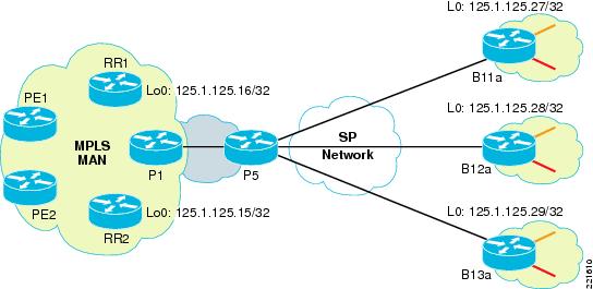
As shown in Figure 4-1, sites B11, B12, and B13 have existing FR connections to WAN aggregation device (P5). The aggregation device is connected to the core P (P1). The three branch routers have loopbacks created that are advertised in the IGP—B11a (125.1.125.27/32), B12a (125.1.125.28/32), and B13a (125.1.125.29/32). The core has two RRs (125.1.125.15 and 16) to which each of the branch PEs is peering.
Figure 4-1 MPLSoL2 Deployment
P5:
mpls label protocol ldptag-switching tdp router-id Loopback0 force!interface Loopback0ip address 125.1.125.11 255.255.255.255!interface GigabitEthernet1/3description To P1 - intf G2/0/1ip address 125.1.100.102 255.255.255.252tag-switching ipmls qos trust dscp!interface Serial2/0/0mtu 1500no ip addressencapsulation frame-relaydsu bandwidth 44210framing c-bitcablelength 10clock source internal!interface Serial2/0/0.1 point-to-pointip address 125.1.201.2 255.255.255.252ip pim sparse-modetag-switching ipframe-relay interface-dlci 17!interface Serial2/0/0.2 point-to-pointip address 125.1.202.2 255.255.255.252ip pim sparse-modetag-switching ipframe-relay interface-dlci 18!interface Serial2/0/0.3 point-to-pointip address 125.1.203.2 255.255.255.252ip pim sparse-modetag-switching ipframe-relay interface-dlci 20!router ospf 10log-adjacency-changesnetwork 125.1.201.0 0.0.0.3 area 0network 125.1.202.0 0.0.0.3 area 0network 125.1.203.0 0.0.0.3 area 0network 125.0.0.0 0.255.255.255 area 0maximum-paths 8
Note
ip cefmpls label protocol ldp!ip vrf red-datard 10:1033route-target export 10:103route-target import 10:103!ip vrf red-voicerd 10:1043route-target export 10:104route-target import 10:104!interface Loopback0ip address 125.1.125.27 255.255.255.255!interface GigabitEthernet0/1.1encapsulation dot1Q 261ip vrf forwarding red-dataip address 125.1.20.1 255.255.255.0!interface GigabitEthernet0/1.2encapsulation dot1Q 262ip vrf forwarding red-voiceip address 125.1.20.1 255.255.255.0!interface Serial1/0/0no ip addressencapsulation frame-relayload-interval 30clock rate 2000000!interface Serial1/0/0.1 point-to-pointip address 125.1.201.1 255.255.255.252mpls ipframe-relay interface-dlci 16!router ospf 10log-adjacency-changesnetwork 125.1.125.27 0.0.0.0 area 0network 125.1.201.0 0.0.0.3 area 0!router bgp 1no bgp default ipv4-unicastbgp log-neighbor-changesneighbor 125.1.125.15 remote-as 1neighbor 125.1.125.15 update-source Loopback0neighbor 125.1.125.16 remote-as 1neighbor 125.1.125.16 update-source Loopback0!address-family vpnv4neighbor 125.1.125.15 activateneighbor 125.1.125.15 send-community extendedneighbor 125.1.125.16 activateneighbor 125.1.125.16 send-community extendedexit-address-family!address-family ipv4 vrf red-voiceredistribute connectedno synchronizationexit-address-family!address-family ipv4 vrf red-dataredistribute connectedno synchronizationexit-address-familyMulticast
As in a MPLS/Layer 3VPN network, mVPN is the technique to bring the multicast traffic of individual customer (or segmented user groups) across the core network MVRFs are configured for every VRF where multicast traffic is expected on the branch PEs. Default and Data MDTs are also configured if used within the core MPLS network.
Since the Layer 2 service is typically hub and spoke or partially meshed for larger branches, it is recommended to keep the multicast sources at or behind the hub as much as possible. In either case, the WAN aggregator at the hub would end up doing most of the multicast replication as it would be the last hop P for all the branch PEs that are receivers. Thus the multicast replication performance of the aggregator becomes critical to solution scaleability.
Use of Data MDTs with a very low threshold is highly recommended. This would limit the replication at the aggregator to only those branches that have sent a explicit join to the Data MDT. Keeping the threshold low ensures that the Data MDT is spawned for the more specific (S,G) as soon as possible to reduce the overhead at the aggregator.
Most deployments use either PIM SSM or PIM SM with RP in the MPLS core. PIM-SM tries to constrain data distribution so that a minimal number of routers in the network receive it. Packets are sent only if they are explicitly requested at the RP. By default, members of a multicast group receive data from senders to the group across a single data distribution tree rooted at the RP. PIM-SSM is similar to PIM-SM with the additional ability to report interest in receiving packets from specific source addresses to an IP multicast address. It does not use RPs but uses source-based forwarding trees only. While PIM SSM provides the simplest implementation, it does create additional memory overhead since the number of mroutes now increases. This is not expected to be an issue in most enterprise deployments.
Example:
Continuing with our earlier example, we add MVPN to sites B11, B12, and B13. We have Data MDT setup with very low threshold (1kbps) to ensure that it gets initiated almost instantly for any stream. We will use PIM SSM for the Data MDTs.
B11a:
ip vrf red-datard 10:1033route-target export 10:103route-target import 10:103mdt default 239.232.10.3mdt data 239.232.20.32 0.0.0.15 threshold 1!ip multicast-routingip multicast-routing vrf red-data!interface Loopback0ip address 125.1.125.27 255.255.255.255ip pim sparse-mode!interface GigabitEthernet0/1.1encapsulation dot1Q 261ip vrf forwarding red-dataip address 125.1.20.1 255.255.255.0ip pim sparse-mode!interface Serial1/0/0.1 point-to-pointip address 125.1.201.1 255.255.255.252ip pim sparse-modempls ip!ip pim ssm range 1ip pim vrf red-data rp-address 3.3.3.11!access-list 1 permit 239.232.0.0 0.0.255.255
Note
QoS
Existing WAN Edge QoS models can still be implemented with MPLS WAN setup. At the headend the expectation is that a interface with high link speed is used (DS3 and up). At these speeds, link-efficiency policies such as LFI and cRTP are not required. The Enterprise QoS SRND recommends 5-11 classes at the WAN edge. At the branches, the PE could be configured to map the COS to DSCP, but in our example we assume that the packets are already marked with the appropriate DSCP. If the branches have slow/medium speed links (<T1), then a 3-5 class model is recommended.
The traffic classification has to be done based on EXP (3 bits). This restricts us to at the most 8 classes at the edge. The original IP packet DSCP are preserved and only the 3 bits of IP precedence are copied on to the outgoing EXP at the branches. There are three different variations of core QOS behaviors within a MPLS network:
•
•
•
Example:
We use a modified version of the 8 class model from the Enterprise QoS SRND (scavenger combined with bulk data) with dual LLQ for voice and video. Recall that MVPN encapsulates the multicast packets into GRE and forwards it as IP packets and not MPLS. So we must ensure that the MVPN packets are accounted for in a specific class, otherwise they would be dropped into the default class. We use the video class for interactive video, streaming video, and any other multicast traffic. A hierarchical policy is applied to shape all the traffic leaving the branch PE.
The sample below shows branch PE configuration for QoS. Similar configuration can be applied at the aggregator adjusted for the link speed.
B11a:
class-map match-any Bulk-Datamatch mpls experimental topmost 1class-map match-any Videomatch mpls experimental topmost 4match ip precedence 4class-map match-any Network-Controlmatch mpls experimental topmost 6match mpls experimental topmost 7class-map match-any Critical-Datamatch mpls experimental topmost 2class-map match-any Call-Signalingmatch mpls experimental topmost 3match ip dscp af31class-map match-any Voicematch mpls experimental topmost 5!policy-map WAN-EDGEclass Voicepriority percent 18class Videopriority percent 15class Call-Signalingbandwidth percent 5class Network-Controlbandwidth percent 5class Critical-Databandwidth percent 27random-detect dscp-basedclass Bulk-Databandwidth percent 5random-detect dscp-basedclass class-defaultbandwidth percent 25random-detectpolicy-map MQC-FRTS-1536class class-defaultshape average 1460000 14600 0service-policy WAN-EDGE!interface Serial1/0/0.1 point-to-pointip address 125.1.201.1 255.255.255.252mpls ipframe-relay interface-dlci 16class FR-MAP-CLASS-1536!map-class frame-relay FR-MAP-CLASS-1536service-policy output MQC-FRTS-1536Voice and VRFs
Typically voice traffic has no dependency on the network type since they are just transported as IP packets and require correct QoS behavior applied to them. An exception is when routers are used as gateways for voice services because a lot of voice features and protocols deployed at the branches are not VRF aware (for example, SRST, CME, etc.). Thus just getting the voice traffic in a VRF could be a challenge. This is apart from larger issues of having the voice in a VRF—while you can have the IP phones within a VRF, other services such as softphones VT advantage may be in a different VRF. There are challenges in implementing Inter-VRF IP communications, but they are not discussed here as it is part of the larger virtualization architecture issue. The current recommendation is to keep voice within the global space especially at the branches. At the hub they could remain in the global space or would have to be placed within its own VRF. We look at both options, getting the voice in the VRF at the branch as well keeping it in the global table at the branch.
Voice in a VRF at the Branch
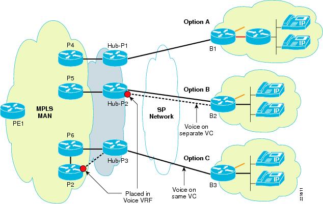
If we need to put the voice in the VRF and still want to use voice features such as CME, then the only way to currently do this is by having two separate routers at the branch. The branch edge router still has a voice VRF configured but treats it like any other VRF. It has a second router (such as a low end ISR) connected to its voice VRF VLAN. The CCME is implemented in the second router, as shown in Figure 4-2 (option A), has all the phones attached to it. Cost might be an issue with this approach as it requires two routers at every such branch site.
Figure 4-2 MPLSoL2—Voice and VRFs
Voice Global at the Branch
If we choose to keep the voice in the global space at the branch, then a single router would be sufficient. The voice VLAN is connected to the branch router but remains in the global space. If the voice is gong to be kept in the global space within the hub network as well, then it can be transported over the existing connection to the hub (MPLS-switched traffic and IP-forwarded traffic share the same link). But at the hub if this traffic needs to be placed within its own VRF, then we would need a separate logical link between the hub and the spoke. This link would be in the global space at the spoke, but be placed within the voice VRF at the hub as shown in Figure 4-2 (option B). The reason we need a separate logical link is that the MPLS link at the hub cannot be placed in a VRF since its configured with "mpls ip" for tag switching. This can potentially increase the circuit cost for the Layer 2 service.
A third option as shown in Figure 4-2 (option C) is to have a separate link at the headend to a PE device which puts the traffic into a VRF. We would need proper routing mechanisms at the hub including route filtering to control the route advertisement within the core network as well as voice VRF.
System Scale and Performance Considerations
Some of the considerations that need to be accounted for from a system scale and performance perspective:
•
•
•
•
Note