Table Of Contents
Cisco Unified Communications Voice over Spoke-to-Spoke DMVPN Test Results and Recommendations
Issues to Address with Voice Over Spoke-to-Spoke DMVPN
Co-location of Voice Main Site and DMVPN Hub
Benefits and Drawbacks of the Solution
Influence of DMVPN on Latency, Jitter, and Packet Loss
Allocation of Available Bandwidth Among Traffic Classes
Management of Traffic Using the Low-Latency Queue
Call Admission Control for Internet Key Exchange
Mitigation of Path Switch Jitter Distortion
Selection of Spoke Router Hardware
Monitoring DMVPN Performance for Voice
Using IP SLA for Monitoring of DMVPN Performance
Implementation and Configuration
Location-Based Call Admission Control
SRST and PSTN Gateway at Each Remote Site
IP SLA Options Relevant to Voice Over DMVPN
Software and Hardware Environment
Tunnel Overhead for Idle Tunnels
Tunnel Overhead for Active Tunnels
Cisco 7206 Hub Router Configuration
7609 IPsec Concentrator Configuration
MGCP Gateway and SRST Router Configuration
Cisco Unified Communications Voice over Spoke-to-Spoke DMVPN Test Results and Recommendations
This document describes the interoperability of the Cisco Dynamic Multipoint VPN (DMVPN) solution with voice over IP (VoIP), which is part of the Cisco Unified Communications solution. This document provides some specific results and recommendations resulting from testing conducted by the Cisco Global Government Systems Group (GGSG) Government Systems Engineering team. The testing was specifically intended to validate the Unified Communications solution in conjunction with a specific spoke-to-spoke DMVPN solution already deployed by a service provider on behalf of a U.S. government agency; however, many of the concepts discussed are applicable to any deployment of VoIP with spoke-to-spoke DMVPN.
The following detailed design guides for the solutions tested already exist:
•
Cisco Unified Communications SRND Based on Cisco Unified CallManager 4.x— http://www.cisco.com/en/US/docs/voice_ip_comm/cucm/srnd/4x/uc4_2.html
•
•
This document extends the scope of the existing documents with a focus on deploying a Cisco Unified Communications solution together with a spoke-to-spoke DMVPN network. The purpose is to provide additional solution design guidance, including predicting performance of particular platforms as spoke routers and configuring the solution to ensure high voice quality.
The data in this document is the result of testing in the GGSG test lab with a sufficient scale of the DMVPN and Unified Communications solutions to mimic real-world behavior. More information on the test methodology and results is provided in References.
Overview
Cisco Unified Communications products are designed and tested with various types of WANs in mind. For example, Call Admission Control (CAC) takes into account the possibility of limited WAN bandwidth over which to transport media. Such features work in conjunction with QoS policies on WAN gateway routers to ensure that available media and call control signaling bandwidth is available.
The standard Unified Communications configurations apply to a deployment using the DMVPN network for media transport. This includes configuration of the Cisco Unified CallManager and Unity servers, gateways, IP phones, and LAN infrastructure.
To account for DMVPN network topology attributes and behavior, some additional requirements and best practices apply. These are discussed throughout this document.
Issues to Address with Voice Over Spoke-to-Spoke DMVPN
There are the following main concerns about the interoperability of Cisco Unified Communications with spoke-to-spoke DMVPN networks:
•
•
See References for more information on these issues.
These issues are addressed by using the following voice solution attributes:
•
•
•
•
•
This remainder of this document addresses these issues and provides additional best practices information.
Limitations of this Document
Significant variations are possible when designing a DMVPN network and the underlying WAN. The test approach, results, measurements, and conclusions in this document are most applicable to the DMVPN network used by the target government customers with a single-cluster Cisco Unified Communications topology. Although the strategies and best practices discussed are generally applicable, the detailed characteristics of other DMVPN deployments need to be considered. Cisco did not examine other variations in topology and scale for this document.
Solution Description
This document is focused on a government network deploying voice over IP using an existing DMVPN network for media and signaling transport between the main office and branch offices. This deployment uses the following solutions in combination:
•
•
•
The existing DMVPN network of the customer has a dual-hub, dual DMVPN cloud topology with a dual-tier headend architecture; and approximately 2000 spoke routers connected via the MPLS network of the WAN service provider. The same service provider operates the DMVPN network on behalf of the government customers. This includes hub complex routers at centralized data centers and spoke routers at each customer site. The second DMVPN cloud uses a different service provider network.
The DMVPN network is shared among multiple agencies in a U.S. government department. The DMVPN solution is configured to provide spoke-to-spoke tunnels between any two spoke routers. The DMVPN network has a single level of spokes subtending the hub level.
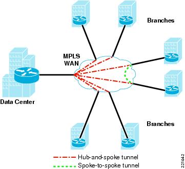
V3PN QoS recommendations were followed when deploying the DMVPN components, including Low-Latency Queuing (LLQ) and Class-Based Weighted Fair Queuing (CBWFQ) at the interfaces between the spoke routers and the service provider network. The service provider network maintains the Differentiated Services Code Point (DSCP) information in each packet as the packet traverses the WAN. Enhanced Interior Gateway Protocol (EIGRP) distributes routes to each spoke router on the DMVPN cloud, and Next Hop Routing Protocol (NHRP) resolves the DMVPN subnet (tunnel) address to the non-broadcast multiple access (NBMA) IP address of the destination spoke router. Figure 1 shows the general DMVPN topology.
Hub-and-spoke DMVPN topologies were not considered because the target customers have access only to a spoke-to-spoke DMVPN network.
Figure 1 DMVPN Topology
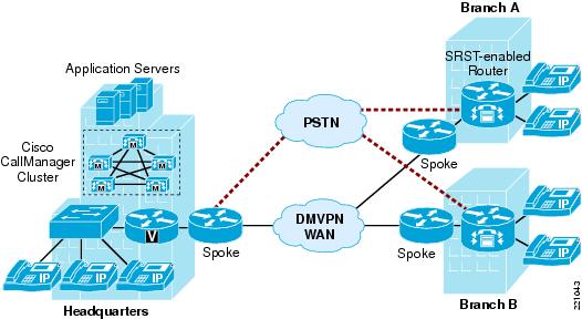
The Cisco Unified Communications solution to be deployed uses the "multisite WAN with centralized call control" topology described in the Cisco Unified Communications SRND based on Cisco Unified CallManager 4.x. The scalability needs of the target customers range from a single main site with 400 users and 3 remote sites with 200 users each (total 1000 users) to a main site with 5000 users and up to 100 remote sites with up to 250 users each (total 30,000 users). The testing did not include clustering over the WAN or multiple clusters with intercluster trunks because these topologies are not required for the deployment scale. Specifically, clustering over the WAN is an option for branch office sites requiring more lines than supported by SRST and require multiple-cluster topologies when the number of lines is more than the capacity of a single cluster or the customer has more large branch office sites than supported by the clustering-over-the-WAN topology. Figure 2 shows the multisite WAN with centralized call control topology integrated with a DMVPN WAN.
Each agency deploys a separate Cisco Unified Communications solution using PSTN connectivity between agencies.
Figure 2 Multisite WAN with Centralized Call Control Topology
Each remote site is equipped with a PSTN gateway router with SRST capability. The new systems are replacing legacy PBX systems or upgrading standalone Cisco Unified CallManager clusters or multisite WAN with centralized call control that are currently using the PSTN for intersite traffic.
Notice that the main site connects to the DMVPN as a spoke, so communication between the main site and any remote site (or between remote sites) is via a spoke-to-spoke tunnel. The permanent tunnel to the hub from each spoke router is normally only briefly used for voice traffic while the spoke-to-spoke tunnel is first being established. The details of the DMVPN and WAN topologies are transparent to the voice solution except for their impact on latency, jitter, and packet loss.
Co-location of Voice Main Site and DMVPN Hub
This test effort did not examine the topology where the Cisco Unified CallManager cluster is located behind a DMVPN because the target customers have access only to the DMVPN via the spoke routers. This is a characteristic of this particular DMVPN network that does not apply to all DMVPN deployments. If the Cisco Unified CallManager cluster is placed behind a DMVPN hub, the voice requirements would be similar because dynamic spoke-to-spoke tunnels would still be generated between branch office sites. The main difference is the nature of the connections between the branch offices and the main site. These would be permanent static tunnels instead of dynamic tunnels kept active by call control keepalive traffic.
Benefits and Drawbacks of the Solution
Spoke-to-spoke DMVPN provides clear benefits for Cisco Unified Communications compared with a hub-and-spoke topology. Spoke-to-spoke tunnels can provide a reduction in end-to-end latency by reducing the number of WAN hops and decryption/encryption stages. In addition, DMVPN offers a simplified means of configuring the equivalent of a full mesh of point-to-point tunnels without the associated administrative and operational overhead. The use of spoke-to-spoke tunnels also reduces traffic on the hub, permitting bandwidth and processing capacity savings.
Spoke-to-spoke DMVPN networks, however, have the following caveats associated with them:
•
•
•
•
Influence of DMVPN on Latency, Jitter, and Packet Loss
As with any WAN-based transport for voice, the voice quality of intersite calls over a DMVPN network is impacted by latency, jitter, and packet loss. The following sections describe in more detail how the DMVPN solution influences these factors.
Latency
The following factors can contribute to latency on the DMVPN network:
•
•
•
•
•
A WAN connection between sites has some latency associated with normal operation. DMVPN induces an additional small amount of latency from encrypting and decrypting packets. This was measured as an average of 2 ms on the spoke-to-spoke path (a single encryption and decryption). Other sources of WAN latency are not unique to DMVPN. Latency is higher via the spoke-hub-spoke path because of additional hops, the possibility of additional propagation time, additional decryption/encryption, and the processing overhead on the hub router(s).
Jitter
The amount of jitter (delay variation between packets) is influenced by the following:
•
•
•
One factor that introduces a transient jitter into a VoIP stream is a change in the path of the RTP stream from spoke-hub-spoke to direct spoke-to-spoke. If two spokes have an established spoke-to-spoke tunnel before initiation of the RTP stream, there is no cut-through issue. The spoke-to-spoke tunnel may have been initiated by a previous VoIP call or some data traffic between the two spokes.
Note
Spoke-to-spoke tunnels are dynamically created as the need for them arises. This process takes a relatively small amount of time (less than one second), but the sequence of events has the potential of momentarily impacting voice quality. While establishing the spoke-to-spoke tunnel, the network routes the packets via the spoke-hub-spoke path. This requires a packet to traverse the WAN twice (once from the originating spoke to the hub and another from the hub to the terminating spoke) and to be decrypted/encrypted at the hub, which results in additional latency compared with the spoke-to-spoke path.
Immediately after the spoke-to-spoke tunnel becomes available, new voice packets are transmitted along this new path. This scenario can cause out-of-sequence packets and momentary high inter-arrival jitter at the terminating spoke router as packets arrive from both paths. The jitter buffer algorithm on the terminating VoIP device attempts to account for the jitter but may sometimes be unable to conceal the discontinuity without some audible distortion. A user might describe the sounds as a glitch, gap, or splice, or the sound might not be noticed at all.
Note
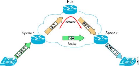
There are jitter two scenarios caused by the path switch to the spoke-to-spoke tunnel. The usual case (see Figure 3) is when the spoke-hub-spoke path has more latency than the spoke-to-spoke path. When traffic from the spoke-to-spoke tunnel begins arriving at the destination endpoint, it overlaps with an earlier portion of the media stream that traversed the hub path. The endpoint sees the out-of-sequence packets and reorders them before playing them out; or, if the jitter buffer is too full to accommodate the new packets, discards the older packets and retains the newer packets for playout. If the latency difference is significant enough (greater than 100ms), a user may notice a portion of a syllable missing (a "splice").
Figure 3 Jitter and Out-Of-Sequence Packets Because of Path Switch—Spoke-To-Spoke Path Faster
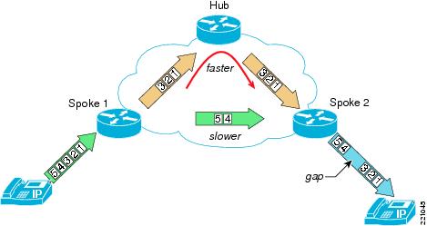
Figure 4 shows the other case. If the spoke-to-spoke path has more latency than the spoke-hub-spoke path, the terminating endpoint detects an unexpected increase in delay (jitter) between the last packet traversing the spoke-hub-spoke path and the first packet traversing the spoke-to-spoke path. If the latency difference is significant enough, a user may notice a period of silence or white noise within the speech.
Figure 4 Jitter Because of Path Switch—Hub Path Faster
Measurements taken for this test effort show that all tested Cisco endpoints were able to avoid or conceal an audio distortion provided that the difference in latency between the spoke-hub-spoke path and the direct spoke-to-spoke is 50 ms or less. Higher latency differences up to 100 ms provided acceptable voice quality for the overlapping stream case (hub path slower) because the momentary audio distortion was almost imperceptible. When there is more latency on the spoke-to-spoke path, the tolerance is lower. Most Cisco endpoints concealed the effects of jitter up to 25 ms, but at 50 ms and higher, some distortion begins to be audible.
Although this behavior impacts voice quality, it has proven acceptable to the user community. Further details and mitigation approaches are provided in Mitigation of Path Switch Jitter Distortion.
Risk of Packet Loss
Packet loss can occur for a variety of reasons, but most often oversubscription of allocated bandwidth is the cause. This can be because of overloading physical interfaces or exceeding bandwidth allocated to QoS queues.
Because spoke-to-spoke tunnels are established dynamically, there is no QoS policy per spoke-to-spoke tunnel that queues, shapes, or polices traffic to manage bandwidth associated with that specific tunnel. Instead, per-interface policies are used. These policies maintain control over the traffic traversing the entire interface, which may include multiple spoke-to-spoke tunnels. There is the potential for multiple spokes to direct more voice traffic to a particular spoke than the interface or low-latency queue of the spoke has bandwidth to receive. Likewise, traffic sources within the local network may attempt to direct more voice traffic out through the DMVPN spoke router than there is available bandwidth. This can lead to poor voice quality.
The components of the Cisco Unified Communications solution are not aware of the specifics of the DMVPN network. CAC can deny a call over the WAN if all bandwidth, at either the originating or terminating spoke, has been allocated to other calls. CAC protects existing calls from the risk of an additional call overflowing the low-latency queue resulting in packet loss across all calls on that interface. Although a Cisco Unified CallManager cluster can be configured to keep track of the WAN bandwidth used between regions (with one region per spoke site, in general), it is otherwise considered "topology unaware". Thus, there is a risk that changes in network topology or bandwidth availability could impact voice quality. Per-location bandwidth values must take LLQ bandwidth allocations and encryption and data link layer protocol overhead into account.
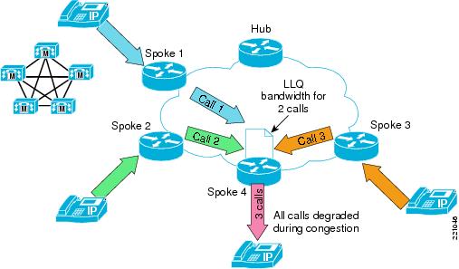
Figure 5 shows a simplified example of voice quality degradation in the absence of CAC. The low-latency queue for traffic leaving the WAN toward Spoke 4 is configured to support two calls. Each originating spoke router also has the low-latency queue bandwidth for two calls in the outgoing direction to the WAN. Assuming congestion conditions on all interfaces, each originating spoke router is easily able to route the media stream for a single call with no packet loss, but when all three streams converge at Spoke 4, one-third of the voice packets are dropped because of the policing function of the low-latency queue.
Figure 5 Degradation Of Voice Traffic Without Call Admission Control
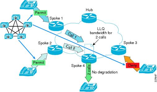
If location-based CAC is enabled (see Figure 6), a third call is denied access to the WAN so that the capacity of the low-latency queue to and from spoke 4 is not exceeded.
Figure 6 Operation Of Call Admission Control
Planning and Best Practices
When you plan to deploy Cisco Unified Communications capability using a DMVPN network for signaling and media transport between sites, consider the following factors:
•
•
•
•
•
•
Additional WAN planning strategies are provided in Cisco Unified Communications SRND Based on Cisco Unified CallManager 4.x.
Physical Bandwidth Sizing
The amount of bandwidth between the spoke router and the WAN is based on standard traffic engineering methodology. Among the factors influencing this decision are the following:
•
•
•
•
•
•
•
Note
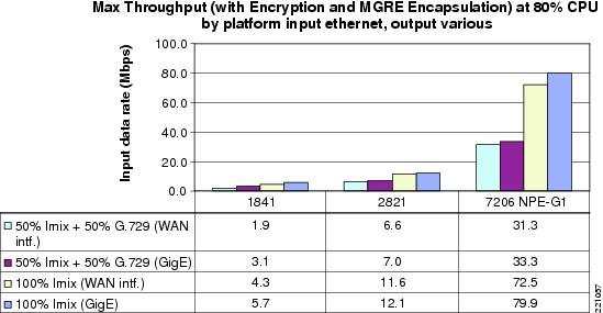
When you calculate required bandwidth, consider that IPsec encryption and Multipoint Generic Routing Encapsulation (mGRE) tunneling for DMVPN adds significant overhead compared with the small payload size of a G.729 RTP packet. The Layer 3 data rate for a G.729 call (50 pps) is 24 kbps in each direction. Encrypting the media stream using IPsec Tunnel Mode for mGRE increases that rate to approximately 56 kbps. Added to this is the Layer 2 overhead, which varies by interface type from 4 bytes to 14 bytes per packet. See Voice and Video Enabled IPsec VPN (V3PN) SRND for more details. Table 1 lists the estimated bandwidth per call for the interfaces on the target DMVPN spoke routers for both G.729 and G.711. Use of the G.729 codec is generally recommended for bandwidth conservation on WAN links.
Note
In the case of the target government customers, the uplinks to the service provider WANs are already established and administered by the service provider, but deployment of additional voice traffic may require increases in bandwidth on those uplinks after considering call traffic patterns. A standard method of estimating intersite call traffic is to study current traffic patterns on the system being replaced and to add additional volume based on interviewing the customer regarding call rates, durations, peak traffic times, growth plans, and so on. See Cisco Unified Communications SRND Based on Cisco Unified CallManager 4.x and Voice and Video Enabled IPsec VPN (V3PN) SRND for more information.
Allocation of Available Bandwidth Among Traffic Classes
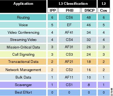
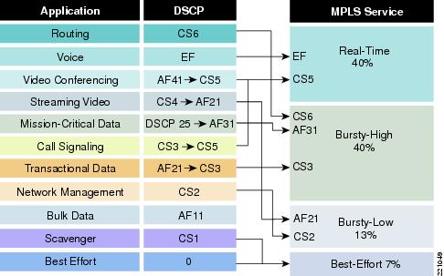
Each spoke site has different bandwidth requirements and differences in expected amounts of traffic for each class. In this case for the targeted government customers, the primary WAN service provider offers a range of pre-defined QoS policies that can be selected for deployment on the spoke router. Table 2 lists the bandwidth allocation by traffic class offered by the service provider. The example sites modeled for this test used profile 110, which provides 40 percent of interface bandwidth for CoS1 (DSCP 46; per-hop behavior EF) and a percentage of the remaining bandwidth for other classes of traffic (Figure 7 and Figure 8).
To make the best use of location-based call admission control (CAC), the bandwidth allocated to voice needs to be allocated symmetrically at each end of the serial link. This means that if 40 percent of the interface bandwidth is allocated to voice on the spoke router uplink to the WAN, the router at the other end needs to have the same percentage allocated for voice traffic toward the spoke router. In addition, the spoke router link to a secondary DMVPN cloud also needs to have at least the same bandwidth allocated to voice as the link to the primary DMVPN cloud.
Figure 7 Classification of Application Traffic to DSCP Marking
Figure 8 Mapping of DSCP Per-Hop Behavior to Service Provider Classes
Management of Traffic Using the Low-Latency Queue
Packets marked as DSCP 46 (per-hop behavior EF) retain this marking after encryption by the DMVPN spoke router and are routed through a dedicated low-latency queue. The service provider network keeps the real-time priority across the WAN because of the marking. If adequate bandwidth is reserved for the low-latency queue, latency, jitter, and loss should be minimized for these packets. However, voice traffic can exceed reserved bandwidth and, under congestion conditions, voice quality can be impacted as packets drops increase.
Location-based CAC
For DMVPN, Cisco recommends configuring location-based CAC on the Cisco Unified CallManager. Location-based CAC tracks the bandwidth in use for media streams controlled by the Cisco Unified CallManager. When insufficient bandwidth remains to support a new media stream, calls are intercepted or rerouted. This helps prevent the low-latency queue from overflowing and causing voice quality problems because of packet loss. When a call ends, its bandwidth is made available to new calls.
Provided that all sources of DSCP 46 (per-hop behavior EF) traffic are accounted for by the value for maximum voice bandwidth for each Cisco Unified CallManager location, location-based CAC prevents voice quality issues in many situations. However, because the Cisco Unified CallManager does not have any information about the actual network topology, location-based CAC cannot account for temporary network conditions such as a partial loss of bandwidth along a certain path (for example, one link in a multilink interface), so its effectiveness has some limits. An alternate strategy using RSVP for CAC is not yet supported on DMVPN tunnel interfaces.
See the Cisco Unified Communications SRND Based on Cisco Unified CallManager 4.x ("Call Admission Control" chapter) for more information regarding the capabilities and limitations of topology-unaware CAC. See Location-Based Call Admission Control for an example of configuring location-based CAC for DMVPN.
Call Admission Control for Internet Key Exchange
Cisco IOS-based routers provide the capability of limiting the number of Internet Security Association and Key Management (ISAKMP) security associations (SA). This can be based on the number of existing ISAKMP SAs or on the percentage of critical system resources (CPU utilization and memory buffers). IKE CAC can prevent a spoke router from being overwhelmed if it is suddenly inundated with SA requests. This feature does not restrict voice bandwidth utilization directly but it can safeguard spoke router performance from a DMVPN perspective.
See the DMVPN Design Guide and Cisco IOS Security Configuration Guide, Release 12.4—Call Admission Control for IKE for more information.
Assessment of WAN Performance
According to recommendation G.114 of the International Telecommunication Union (ITU), if end-to-end latency is kept below 150 ms, most applications experience essentially transparent interactivity. In practice, satisfactory results are attainable end-to-end latency greater than 150 ms, but the user experience approaches dissatisfaction with latency greater than 300 ms.
To meet this recommendation for IP voice over DMVPN, Cisco recommends following the guidelines in the Voice and Video Enabled VPN SRND regarding WAN service provider performance. Specifically, WAN contribution to jitter should be less than or equal to 20 ms, one-way latency across the WAN should be less than or equal to 60 ms, and packet loss less should be less than or equal to 0.5 percent. WAN QoS, particularly low-latency queuing with guaranteed bandwidth for voice packets, is essential for voice over DMVPN deployments to meet these requirements.
Cisco recommends that you monitor the performance of your WAN to ensure that these guidelines are being met. The IP Service Level Agreements (IP SLA) command provides effective ways of measuring the performance of the WAN and the DMVPN for these recommendations. See G.729 Codec for more information.
Because of the dynamics of establishing a spoke-to-spoke tunnel and the effect on endpoint jitter buffers, Cisco recommends that the difference in latency between the spoke-hub-spoke path and the spoke-to-spoke path be minimized. See Mitigation of Path Switch Jitter Distortion for more information.
Mitigation of Path Switch Jitter Distortion
Even if the average one-way latency across a spoke-to-spoke DMVPN network is within the guidelines, it is possible that a brief period of higher latency will occur when the initial Real-Time Protocol (RTP) packets of a call traverse the spoke-hub-spoke path if that call triggers a new spoke-to-spoke tunnel. Test results show that momentary audio distortion because of jitter when the RTP packets switch from the spoke-hub-spoke path to the spoke-to-spoke path is avoided when the difference in latency between the paths is 50 ms or less. Latency differences between 50 ms and 100 ms produce acceptable audio quality, but if the latency difference is above 100 ms, a momentary audio distortion may be audible at the beginning of a call that triggers a new spoke-to-spoke tunnel. Latency differences higher than 100 ms are associated with increasingly noticeable momentary audio distortions at the time the spoke-to-spoke tunnel starts to be used.
In most cases, the latency difference between the spoke-hub-spoke path and the direct spoke-to-spoke path is under 100 ms. If the latency difference between paths on your network is more than 100 ms, consider one of the following approaches:
•
•
•
•
Note
Selection of Spoke Router Hardware
The spoke router needs to be adequately sized for the expected level of traffic. Considering the performance information in this document and in the Voice and Video Enabled IPsec VPN SRND and the Dynamic Multipoint VPN Design Guide documents, select a platform that supports your estimates of traffic through the DMVPN spoke router.
Table 3 lists the data and voice call capacity of three spoke router platforms used on the customer DMVPN network. For each of these platforms, two physical interfaces are shown to permit easier comparison between the platform performance of each router. The number of voice calls shown is based on 50 percent of the total bit rate divided by the bit rate per G.729 call with encryption, tunneling, and Layer 2 overhead.
Monitoring DMVPN Performance for Voice
There are several useful techniques for monitoring DMVPN performance. Some require access to the spoke router console or network management interface, others can be used inside the local network. The following sections discuss these techniques.
Using IP SLA for Monitoring of DMVPN Performance
Useful statistics maintained on the DMVPN spoke routers help to assess the condition of the router and the DMVPN network. For example, QoS policy map statistics, DMVPN, IPsec and ISAKMP statistics, interface counters, and CPU and memory statistics. However, in the case of a DMVPN network operated by a service provider, access to the spoke router console may not be readily available.
IP SLA operations are useful for monitoring DMVPN performance without requiring access to the DMVPN spoke router consoles. You can figure them on a Cisco router that has access to the DMVPN network. Preferably, the source and destination routers should be as close as possible to the DMVPN spoke routers so that the results can more easily be attributed to DMVPN and underlying WAN network conditions.
The following information relevant to voice performance is available through IP SLA operations:
•
•
In addition, you may configure the measurements to automatically repeat on a regular basis and have SNMP traps associated with pre-determined thresholds.
For more information, see the "IP SLAs--Proactive Threshold Monitoring of IP SLAs Operations" section of the Cisco IOS IP SLAs Configuration Guide.
Realtime Monitoring Tool
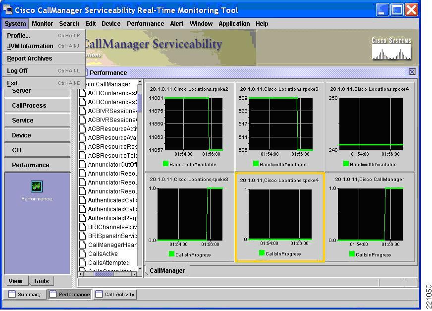
The Cisco Unified CallManager Realtime Monitoring Tool (RTMT) provides visual tracking of many Cisco Unified CallManager performance and configuration metrics. It is helpful to use the RTMT when configuring and monitoring location-based CAC. Bandwidth in use and calls in progress per location can be displayed as shown in Figure 9.
Figure 9 Realtime Monitoring Tool
Spoke Router CLI
Table 4 lists commands that provide information relevant to voice traffic over a DMVPN network from the perspective of the spoke routers.
Summary of Best Practices
This section summarizes the best practices for deploying Cisco Unified Communications using a DMVPN network for signaling and media transport between sites:
•
•
•
•
•
•
•
•
Implementation and Configuration
This section provides configuration recommendations for deploying a Cisco Unified Communications voice solution with a DMVPN for intersite media and signaling transport. The recommendations are based on the assumption that an existing spoke-to-spoke DMVPN network is used. See the Dynamic Multipoint VPN Design Guide for more information on configuring DMVPN.
The configuration information in this section is based on the following assumptions:
•
•
•
•
•
Topology
In the multisite WAN with centralized call processing model used for this set of customers, a single Cisco Unified CallManager cluster provides call processing for all locations on the IP telephony network. The Cisco Unified CallManager cluster usually resides at the main (central or headquarters) location, along with other devices such as phones and gateways. The remote locations contain additional devices, but no Cisco Unified CallManager servers. IP WAN links connect the remote locations to the main location.
Location-Based Call Admission Control
The Cisco Unified CallManager uses "locations" to implement CAC, which enables regulation of audio quality by limiting the amount of bandwidth that is available for calls over links between the locations. For more information, see the "Call Admission Control" section in the Cisco Unified CallManager System Guide.
If CAC is not used to limit the bandwidth on WAN links, an unlimited number of calls may be active on that link concurrently. This situation can cause the audio quality of all calls to degrade as the physical interface of the local or remote DMVPN uplink becomes oversubscribed.
The main location and each remote site has a unique name configured on the Cisco Unified CallManager. The low-latency queue on the spoke router drops packets that exceed the maximum bandwidth of its queue if all bandwidth allocated to other queues is in use (that is, congestion condition exists). Cisco recommends that you specify only the bandwidth dedicated to voice packets for each location.
The Cisco Unified CallManager automatically assumes a specific bandwidth value per call. Because of the overhead associated with mGRE, IPsec, and the Layer 2 protocol being used, a conversion is required when specifying the bandwidth for the location. To limit the number of calls with a higher encapsulation overhead than the Cisco Unified CallManager assumes, the available bandwidth needs to be adjusted downward to achieve the call limit desired. Table 5 lists the per-call bandwidth assumed by the Cisco Unified CallManager in the CAC calculation.
Table 5 Bandwidth Assumed By The Cisco Unified CallManager Location-Based CAC
G.711
80 kbps
G.722
80 kbps
G.723
24 kbps
G.728
16 kbps
G.729
24 kbps
GSM
29 kbps
Wideband
272 kbps
There is no provision in the Cisco Unified CallManager GUI to perform this calculation, so it must be performed outside of the GUI, and the result of the calculation must be used in place of the actual voice bandwidth available. The same concept applies to video bandwidth.
Use the following steps to determine the bandwidth for each location:
1.
2.
3.
Table 6 and Table 7 list an example of the calculation in which the codec is G.729 and the Layer 2 protocol is Frame Relay. In this case, the low-latency queue on the spoke router is allocated 312 kbps. You need to determine this information for each physical interface type.
Table 7 shows some sample adjustments for location configuration because of encapsulation overhead (Frame Relay).
Table 7 Example Adjustments for Location Configuration
(from Table 5)Bandwidth per call leg
24 kbps
56 kbps
Calls per 312 kbps
312 / 24 = 13
312 / 56 = 5.57
Bandwidth to specify in location configuration for 312 kbps
312 K
5.57 * 24 kbps = 133 kbps
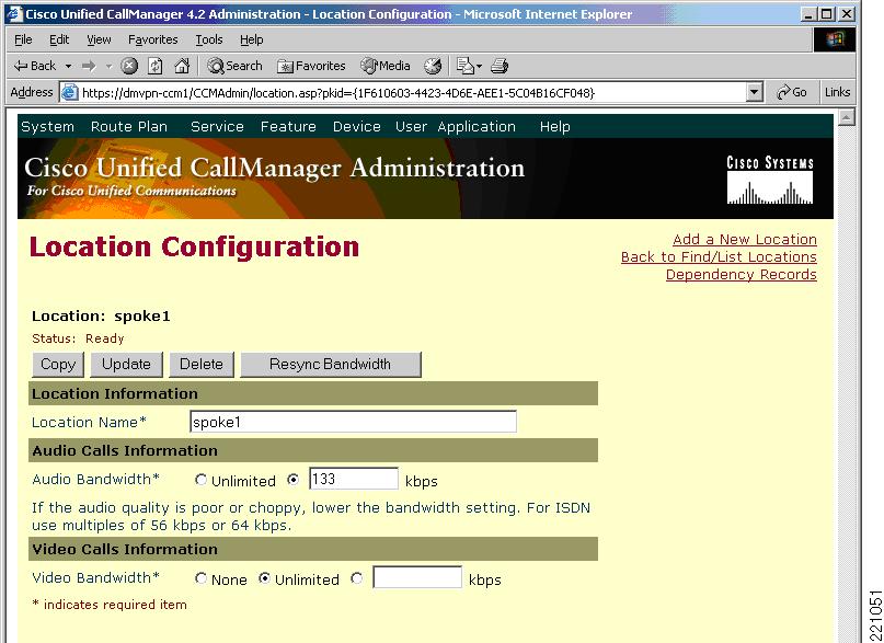
The value you need to input into the Cisco Unified CallManager Location Configuration screen in the Audio Bandwidth field is 133 kbps. If the actual bandwidth allocated to the low-latency queue, 312 kbps is entered without this adjustment, the Cisco Unified CallManager assumes 24 kbps per G.729 call leg, and allows 13 calls to use the 312 kbps bandwidth even though there is only capacity low-latency queue of the DMVPN uplink interface for 5 calls.
Figure 10 shows a location configuration example.
Figure 10 Location Configuration Example
The effectiveness of the location-based CAC feature requires strict control of traffic using the low-latency queue (in this case DSCP 46; per-hop behavior EF voice traffic) through the spoke router. If necessary, the bandwidth specified for a location can be further reduced to account for other traffic using the same code point or another Cisco Unified CallManager cluster directing calls to the DMVPN via the same tunnel interface.
After the locations have been configured, you need to assign to the endpoints (gateway, IP phone, and so on) that are located behind the WAN interface.
Automated Alternate Routing
Automated Alternate Routing (AAR) is a mechanism to provide an alternate route to remote sites when insufficient bandwidth is available to route the call over the primary route. In this deployment, Cisco recommends having the WAN as the primary route for media and a PSTN connection as the alternate route. There are no DMVPN-specific configuration steps for this feature. See the "Dial Plan/AAR" section of the Cisco Unified Communications SRND Based on Cisco Unified CallManager 4.x document for configuration details.
Music On Hold
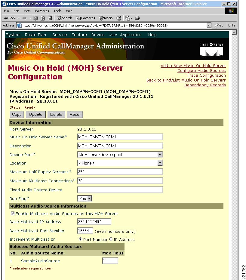
Cisco recommends that you enable the SRST-based Music on Hold (MoH) feature to minimize bandwidth consumption on the DMVPN uplinks for sites where bandwidth is constrained. This feature requires setting up the MoH server in the main/headquarters site to multicast MoH for the IP phones that are local to that location; for example, on an address such as 239.192.240.1. The SRST router is then set to multicast an audio stream on the same address so that the IP phones near the SRST router in the remote site can access the MoH audio. In this case, multicast routing of the MoH stream in the main site needs to be blocked from traversing the WAN, either through a reduced time-to-live count or an access list. When a party at the remote site is placed on hold, the Cisco Unified CallManager instructs the IP phone at that site to listen to 239.192.240.1. It receives the music media stream from the local SRST router instead of from the main site music source across the WAN.
The following steps describe the configuration.
Step 1
Figure 11 Creation Of MoH Server
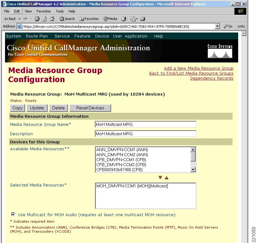
Step 2
Figure 12 Insertion Of The MoH Server In The Media Resource Group
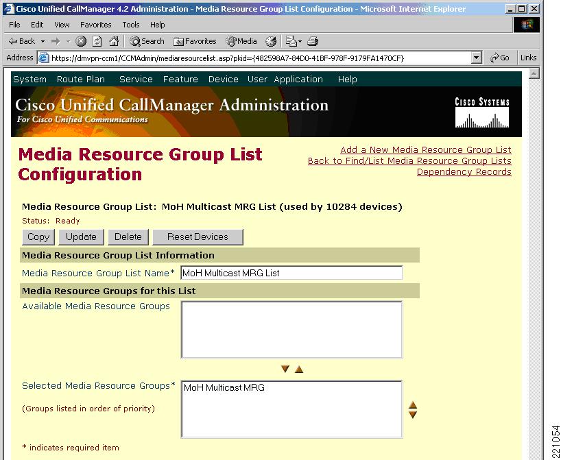
Step 3
Figure 13 Insertion Of Media Resource Group Into Media Resource Group List
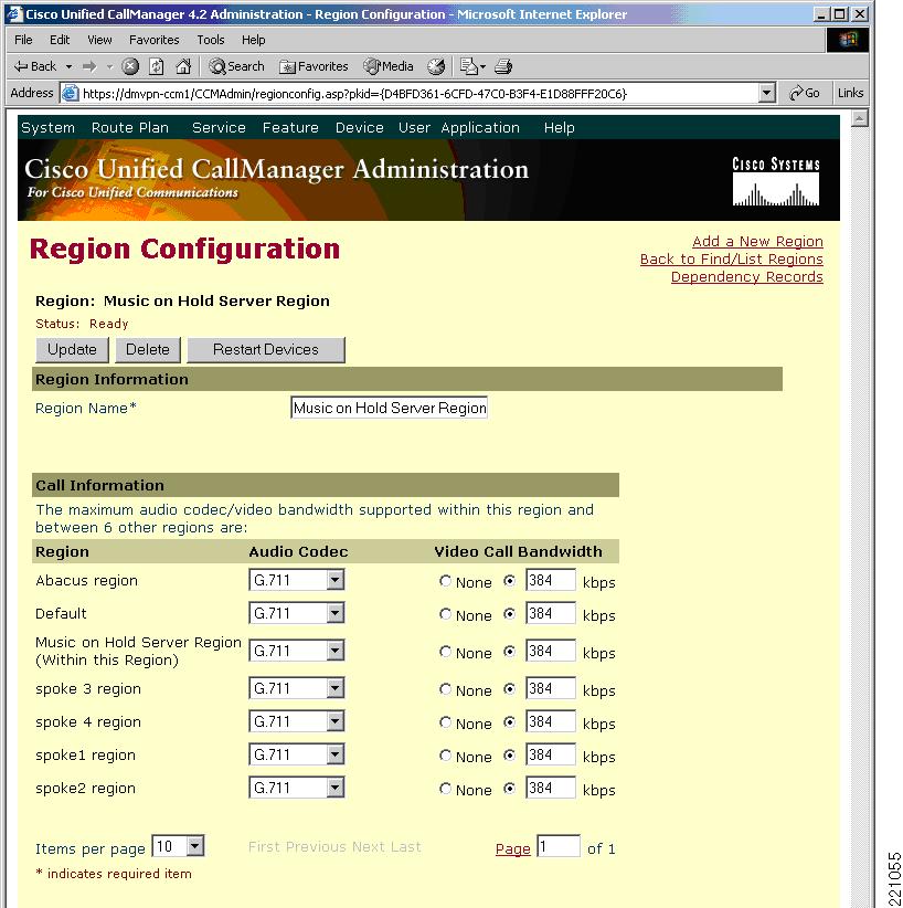
Step 4
Figure 14 Creation Of A Dedicated Region For The MoH
Step 5
ccm-manager music-on-holdcall-manager-fallbackmoh music-on-hold.aumulticast moh 239.192.240.1 port 16384If, as an alternative, you choose to have MoH media unicast across the DMVPN, you can reduce the bandwidth consumed by the music stream by using the G.729 codec and accepting a small reduction in audio fidelity compared with the default G.711 codec.
MoH servers automatically mark audio stream traffic the same as voice bearer traffic DSCP 46 (per-hop behavior EF). Therefore, as long as QoS is properly configured on the network, MoH streams receive the same classification and low-latency queuing treatment as phone-originated RTP media traffic.
For additional information and best practices for MoH, see the Cisco Unified Communications SRND based on Cisco Unified CallManager 4.x and the Integrating Cisco CallManager and Cisco SRST to Use Cisco SRST As a Multicast MOH Resource feature guide.
SRST and PSTN Gateway at Each Remote Site
Each remote site requires local PSTN access, both for PSTN-destined calls and as an alternate route for calls denied bandwidth because of location-based CAC. SRST and gateway configuration for DMVPN follows the standard procedures defined for the Multisite WAN with Centralized Call Control.
WAN Requirements
No configuration is required to verify the WAN requirements, but they are mentioned here because they may require measurement and coordination with the service provider as part of deployment. See Assessment of WAN Performance for best practices related to WAN performance.
Differentiated Services
To minimize latency and jitter, the service provider needs to provide a priority queue for voice packets outbound from the provider edge (PE routers) of the WAN. The bandwidth allocated to the priority queue should mirror the policy on the spoke router. No additional configuration for this requirement is needed because this is already the case for the DMVPN network of the target customer.
Quality of Service
In the case of the target government customers, the QoS configuration on the DMVPN spoke routers is administered by the primary WAN service provider and already supports dedicated bandwidth for voice in the form of a low-latency queue. The following example shows the QoS configuration for the tunnel interface from a spoke router to the DMVPN. The low-latency queue configuration allocates 312 kbps for DSCP 46 (per-hop behavior EF) packets (RTP voice packets) out of an overall T1 frame relay bandwidth of 768 kbps.
! Standard QoS configclass-map match-any PCLASS_COS2_SAAmatch dscp 27class-map match-any PCLASS_COS3_SAAmatch dscp 19class-map match-any PCLASS_COS1_SAAmatch dscp 47class-map match-any PCLASS_COS4_SAAmatch dscp 19class-map match-any PCLASS_COS4match not dscp 1class-map match-any QCLASS_COS4match not dscp 1class-map match-any PCLASS_COS2match dscp af31class-map match-any QCLASS_COS3match dscp 19match dscp af21class-map match-any PCLASS_COS3match dscp af21class-map match-any QCLASS_COS2match dscp 27match dscp af31class-map match-any QCLASS_COS1match dscp 47match dscp efclass-map match-any PCLASS_COS1match dscp efclass-map match-any PCLASS_NMmatch access-group 180class-map match-any PCLASS_RPmatch dscp cs6class-map match-any QCLASS_NMmatch dscp cs6class-map match-any Prec_3match ip precedence 3class-map match-any Prec_2match ip precedence 2class-map match-any Prec_1match ip precedence 1class-map match-any Prec_0match ip precedence 0class-map match-any Prec_7match ip precedence 7class-map match-any Prec_6match ip precedence 6class-map match-any Prec_5match ip precedence 5class-map match-any Prec_4match ip precedence 4!!policy-map remarkclass Prec_0set ip dscp defaultclass Prec_1set ip dscp af21class Prec_2set ip dscp af21class Prec_3set ip dscp af31class Prec_4set ip dscp af31class Prec_5set ip dscp efclass Prec_6set ip dscp af21class Prec_7set ip dscp af21policy-map NMclass PCLASS_RPpolice cir 8000 bc 8000 be 8000conform-action set-dscp-transmit cs6exceed-action set-dscp-transmit cs6class PCLASS_NMpolice cir 8000 bc 8000 be 8000conform-action set-dscp-transmit af21exceed-action set-dscp-transmit af21policy-map COS4class PCLASS_COS4police cir 80000 bc 10000conform-action set-dscp-transmit defaultexceed-action set-dscp-transmit defaultclass PCLASS_COS4_SAAset dscp defaultpolicy-map COS3class PCLASS_COS3police cir 144000 bc 18000conform-action set-dscp-transmit af21exceed-action set-dscp-transmit af22class PCLASS_COS3_SAAset dscp af21policy-map COS2class PCLASS_COS2police cir 280000 bc 35000conform-action set-dscp-transmit af31exceed-action set-dscp-transmit af32class PCLASS_COS2_SAAset dscp af31policy-map COS1class PCLASS_COS1police cir 312000 bc 39000conform-action set-dscp-transmit efexceed-action dropclass PCLASS_COS1_SAAset dscp efpolicy-map D_768Kclass QCLASS_NMbandwidth remaining percent 10random-detect dscp-basedrandom-detect dscp 18 100 200 10random-detect dscp 48 200 300 10service-policy NMclass QCLASS_COS1priority 312compress header ip rtpservice-policy COS1class QCLASS_COS2bandwidth remaining percent 60random-detect dscp-basedrandom-detect dscp 26 200 300 10service-policy COS2class QCLASS_COS3bandwidth remaining percent 30random-detect dscp-basedrandom-detect dscp 18 200 300 10service-policy COS3G.729 Codec
When deploying voice in a WAN environment, Cisco recommends the lower-bandwidth G.729 codec for any voice calls that traverse WAN links because this practice provides bandwidth savings compared to G.711 at the expense of a small reduction in audio fidelity.
To configure a codec for WAN calls, configure a "region" to represent points in the network that impact codec selection. To configure G.729 for intersite calls and G.711 for intrasite calls, a unique region can be created for each remote site, and a codec option can be selected both for calls within that region and for calls to other regions. See the Cisco Unified Communications SRND Based on Cisco Unified CallManager 4.x for more information.
IP SLA Options Relevant to Voice Over DMVPN
This section provides some sample IP SLA operations that are useful in assessing DMVPN performance for voice traffic. Multiple other options are supported by IP SLA command. For more information, see the Cisco IOS IP SLAs Configuration Guide, Release 12.4T.
To obtain performance information about the DMVPN network, Cisco recommends the UDP-jitter operation. Configure the codec and ToS options to simulate G.729 voice packets with DSCP 46 (per-hop behavior EF). See the example titled "UDP Jitter with Codec and ToS" in UDP Jitter With Codec and TOS. If there is no pre-existing traffic between two sites, the most useful results are obtained if the interval between measurements is set higher than the NHRP hold time. This provides some information on the latency and jitter during DMVPN spoke-to-spoke tunnel setup. See the example in IP SLA Scheduling Compared With NHRP Holdtime.
If a router with a voice card is available to act as the IP SLA source router, the VoIP operation is also useful. This operation uses Digital Signal Processing (DSP) functions to estimate voice quality. Only the source router needs to have a voice card for this operation. An example of this command is in VoIP Operation.
In each of the following examples, the address 192.168.2.2 represents the destination of the IP SLA probes. All examples assume the following configuration on the terminating router:
ip sla responderUDP Jitter Operation
This IP SLA option measures delay, jitter, and packet loss with UDP. In this example, 10 packets are sent at 20 ms intervals every 30 seconds.
Originating router configuration is as follows:
ip sla 10
udp-jitter 192.168.2.2 5000
frequency 30
ip sla schedule 10 life forever start-time now
Example results are as follows:
router#show ip sla statistics

Round Trip Time (RTT) for Index 10
Latest RTT: 17 milliseconds
Latest operation start time: 14:58:22.494 EST Mon Jan 22 2007
Latest operation return code: OK
RTT Values:
Number Of RTT: 10 RTT Min/Avg/Max: 14/17/21 milliseconds
Latency one-way time:
Number of Latency one-way Samples: 10
Source to Destination Latency one way Min/Avg/Max: 3/3/7 milliseconds
Destination to Source Latency one way Min/Avg/Max: 11/14/16 milliseconds
Jitter Time:
Number of Jitter Samples: 9
Source to Destination Jitter Min/Avg/Max: 4/4/4 milliseconds
Destination to Source Jitter Min/Avg/Max: 1/2/5 milliseconds
Packet Loss Values:
Loss Source to Destination: 0 Loss Destination to Source: 0
Out Of Sequence: 0 Tail Drop: 0 Packet Late Arrival: 0
Voice Score Values:
Calculated Planning Impairment Factor (ICPIF): 0
Mean Opinion Score (MOS): 0
Number of successes: 6
Number of failures: 0
Operation time to live: Forever

router#show ip sla statistics detail

Round Trip Time (RTT) for Index 10
Latest RTT: 17 milliseconds
Latest operation start time: 14:58:22.494 EST Mon Jan 22 2007
Latest operation return code: OK
Over thresholds occurred: FALSE
RTT Values:
Number Of RTT: 10 RTT Min/Avg/Max: 14/17/21 milliseconds
Latency one-way time:
Number of Latency one-way Samples: 10
Source to Destination Latency one way Min/Avg/Max: 3/3/7 milliseconds
Destination to Source Latency one way Min/Avg/Max: 11/14/16 milliseconds
Source to Destination Latency one way Sum/Sum2: 38/170
Destination to Source Latency one way Sum/Sum2: 140/1984
Jitter Time:
Number of Jitter Samples: 9
Source to Destination Jitter Min/Avg/Max: 4/4/4 milliseconds
Destination to Source Jitter Min/Avg/Max: 1/2/5 milliseconds
Source to destination positive jitter Min/Avg/Max: 4/4/4 milliseconds
Source to destination positive jitter Number/Sum/Sum2: 2/8/32
Source to destination negative jitter Min/Avg/Max: 4/4/4 milliseconds
Source to destination negative jitter Number/Sum/Sum2: 2/8/32
Destination to Source positive jitter Min/Avg/Max: 2/2/3 milliseconds
Destination to Source positive jitter Number/Sum/Sum2: 3/8/22
Destination to Source negative jitter Min/Avg/Max: 1/2/5 milliseconds
Destination to Source negative jitter Number/Sum/Sum2: 5/11/35
Interarrival jitterout: 0 Interarrival jitterin: 0
Packet Loss Values:
Loss Source to Destination: 0 Loss Destination to Source: 0
Out Of Sequence: 0 Tail Drop: 0 Packet Late Arrival: 0
Voice Score Values:
Calculated Planning Impairment Factor (ICPIF): 0
Mean Opinion Score (MOS): 0
Number of successes: 6
Number of failures: 0
Operation time to live: Forever
Operational state of entry: Active
Last time this entry was reset: Never
UDP Jitter With Codec and TOS
The UDP jitter IP SLA option can be customized with a codec. By default, 1000 packets are sent in 20 seconds with G.729 size payload and 50 ms interval. All IP SLA options can also have an optional type of service (ToS) value, shown in this example with the equivalent of DSCP 46 (per-hop behavior EF). Because the use of this option consumes low-latency queue bandwidth, the location-based CAC configuration on the Cisco Unified CallManager needs to incorporate this factor.
Originating router configuration is as follows:
ip sla 10
udp-jitter 192.168.2.2 5000 codec g729a
tos 184
frequency 30
ip sla schedule 10 life forever start-time now
Example results are as follows:
router#show ip sla statistics 10

Round Trip Time (RTT) for Index 10
Latest RTT: 16 milliseconds
Latest operation start time: 15:20:03.391 EST Mon Jan 22 2007
Latest operation return code: OK
RTT Values:
Number Of RTT: 1000 RTT Min/Avg/Max: 9/16/69 milliseconds
Latency one-way time:
Number of Latency one-way Samples: 1000
Source to Destination Latency one way Min/Avg/Max: 2/3/17 milliseconds
Destination to Source Latency one way Min/Avg/Max: 6/13/66 milliseconds
Jitter Time:
Number of Jitter Samples: 999
Source to Destination Jitter Min/Avg/Max: 1/2/14 milliseconds
Destination to Source Jitter Min/Avg/Max: 1/3/55 milliseconds
Packet Loss Values:
Loss Source to Destination: 0 Loss Destination to Source: 0
Out Of Sequence: 0 Tail Drop: 0 Packet Late Arrival: 0
Voice Score Values:
Calculated Planning Impairment Factor (ICPIF): 11
MOS score: 4.06
Number of successes: 3
Number of failures: 0
Operation time to live: Forever


router#show ip sla statistics 10 detail

Round Trip Time (RTT) for Index 10
Latest RTT: 16 milliseconds
Latest operation start time: 15:21:33.387 EST Mon Jan 22 2007
Latest operation return code: OK
Over thresholds occurred: FALSE
RTT Values:
Number Of RTT: 1000 RTT Min/Avg/Max: 9/16/60 milliseconds
Latency one-way time:
Number of Latency one-way Samples: 1000
Source to Destination Latency one way Min/Avg/Max: 2/3/20 milliseconds
Destination to Source Latency one way Min/Avg/Max: 6/12/57 milliseconds
Source to Destination Latency one way Sum/Sum2: 3355/13193
Destination to Source Latency one way Sum/Sum2: 12965/180127
Jitter Time:
Number of Jitter Samples: 999
Source to Destination Jitter Min/Avg/Max: 1/2/16 milliseconds
Destination to Source Jitter Min/Avg/Max: 1/3/45 milliseconds
Source to destination positive jitter Min/Avg/Max: 1/2/14 milliseconds
Source to destination positive jitter Number/Sum/Sum2: 175/357/1541
Source to destination negative jitter Min/Avg/Max: 1/2/16 milliseconds
Source to destination negative jitter Number/Sum/Sum2: 171/357/1707
Destination to Source positive jitter Min/Avg/Max: 1/3/45 milliseconds
Destination to Source positive jitter Number/Sum/Sum2: 452/1620/10212
Destination to Source negative jitter Min/Avg/Max: 1/3/43 milliseconds
Destination to Source negative jitter Number/Sum/Sum2: 427/1617/10845
Interarrival jitterout: 0 Interarrival jitterin: 0
Packet Loss Values:
Loss Source to Destination: 0 Loss Destination to Source: 0
Out Of Sequence: 0 Tail Drop: 0 Packet Late Arrival: 0
Voice Score Values:
Calculated Planning Impairment Factor (ICPIF): 11
MOS score: 4.06
Number of successes: 6
Number of failures: 0
Operation time to live: Forever
Operational state of entry: Active
Last time this entry was reset: Never
IP SLA Scheduling Compared With NHRP Holdtime
If you use IP SLA operations to assess spoke-hub-spoke latency, configure the IP SLA operation to have an interval longer than the NHRP hold time. In the following example, the tunnel interface has an NHRP hold time of 300 seconds and the IP SLA operation is configured to occur at intervals of 400 seconds. If there is no other traffic between the source spoke and the destination spoke than the IP SLA probes, this configuration triggers a new spoke-to-spoke tunnel each time it runs.
The initial packets of the UDP jitter test traverse the spoke-hub-spoke path. Although the statistics collected do not specifically identify the latency and jitter of the spoke-hub-spoke path compared with the spoke-to-spoke path, they include the metrics from both paths when calculating the minimum/average/maximum values.
The following example obtains the NHRP holdtime value:
router#show run int tunnel 0 | include interface|holdtime
interface Tunnel0
ip nhrp holdtime 300
Originating router configuration is as follows:
ip sla 10
udp-jitter 192.168.2.2 5000 codec g729a
tos 184
frequency 400
ip sla schedule 10 life forever start-time now
If IP SLA operations are being used to maintain a spoke-to-spoke tunnel, the frequency parameter should be assigned a value less than 2 minutes.
VoIP Operation
This IP SLA option measures latency and jitter, and estimates voice quality using DSP functions in the source router. No DSP hardware is required in the destination router for this operation.
Originating router configuration is as follows:
ip sla 10
voip rtp 192.168.2.2 source-ip 192.168.3.2 source-voice-port 0/0/0:23 codec g729a duration
30 advantage-factor 0
ip sla schedule 10 life forever start-time now
Example results are as follows:
router#show ip sla statistics 10

Round Trip Time (RTT) for Index 10
Type of operation: rtp
Latest operation start time: 16:29:20.278 EST Mon Jan 22 2007
Latest operation return code: OK
Latest RTT (milliseconds): 16
Source to Destination Path Measurements:
Interarrival Jitter: 0
Packets Sent: 750
Packets Lost: 0
Estimated R-factor: 82 MOS-CQ: 4.06
Destination to Source Path Measurements:
Interarrival Jitter: 6
Packets Sent: 721
Packets Lost: 0
Estimated R-factor: 82 MOS-CQ: 4.06 MOS-LQ: 0.00
Operation time to live: Forever
Operational state of entry: Active
Last time this entry was reset: Never


router#show ip sla statistics 10 detail

Round Trip Time (RTT) for Index 10
Type of operation: rtp
Latest operation start time: 16:29:20.278 EST Mon Jan 22 2007
Latest operation return code: OK
Latest RTT (milliseconds): 16
Source to Destination Path Measurements:
Interarrival Jitter: 0
Packets Sent: 750
Packets Lost: 0 Packets MIA: 0
Estimated R-factor: 82 MOS-CQ: 4.06
One way latency(avg/min/max): 2/2/13
Destination to Source Path Measurements:
Interarrival Jitter: 6
Packets Sent: 721
Packets Lost: 0 Packets OOS: 0
Packets Late: 0 Packets Early: 0
Frame Loss: 0
Estimated R-factor: 82 MOS-CQ: 4.06 MOS-LQ: 0.00
One way latency(avg/min/max): 13/7/74
Over thresholds occurred: FALSE
Operation time to live: Forever
Operational state of entry: Active
Last time this entry was reset: Never
UDP Echo
This IP SLA option sends two UDP packets in each direction.
Originating router configuration is as follows:
ip sla 10
udp-echo 192.168.2.2 5000 source-ip 192.168.3.2
ip sla schedule 10 life forever start-time now
Example results are as follows:
router#show ip sla statistics 10

Round Trip Time (RTT) for Index 10
Latest RTT: 15 milliseconds
Latest operation start time: 17:15:29.555 EST Mon Jan 22 2007
Latest operation return code: OK
Number of successes: 1
Number of failures: 0
Operation time to live: Forever

router#show ip sla statistics 10 detail

Round Trip Time (RTT) for Index 10
Latest RTT: 15 milliseconds
Latest operation start time: 17:15:29.555 EST Mon Jan 22 2007
Latest operation return code: OK
Over thresholds occurred: FALSE
Number of successes: 1
Number of failures: 0
Operation time to live: Forever
Operational state of entry: Active
Last time this entry was reset: Never
Test Approach
The following test concepts were used with the goal of validating the proposed solution for IP voice over DMVPN networks:
•
•
•
•
•
•
•
•
Most of the test effort involved testing features that interact with the DMVPN WAN. Features and functions not influenced by topology or WAN performance were not tested.
Software and Hardware Environment
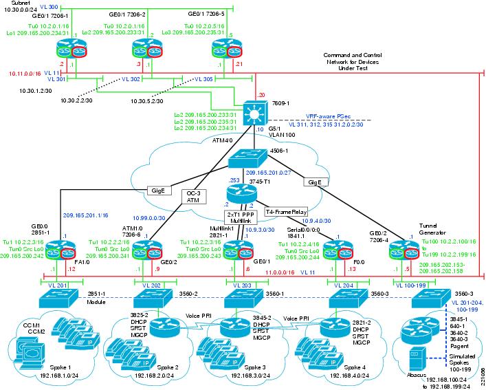
Figure 15 shows the test bed topology. This topology is representative of the DMVPN network deployed by the customer. It is a dual-DMVPN cloud topology with alternate service provider capability. The hub is a dual-tier headend architecture with two Cisco 7206s for one cloud and one Cisco 7206 for the other cloud with a Cisco 7609 performing IPsec with a VPN SPA.
Figure 15 Test Bed Topology
The Cisco 7206, Cisco 2811, and Cisco 1841 spoke routers are deployed on the customer DMVPN network. The MGCP gateways are the Cisco 3845, Cisco 3825, Cisco 2851, and Cisco 2821. In addition, a single Cisco 7206 was used with a multi-VRF configuration to simulate 100 separate spokes. The details of the platforms and their interfaces are listed in Table 8.
Other test environment notes area as follows:
•
•
•
Voice Traffic Model
The voice modeled for the test effort used the following assumptions:
•
•
•
No more than 50 percent of calls are intersite calls, and intersite traffic is evenly distributed across all remote sites.
Because the intrasite traffic is not simulated, the number of simulated IP phones is 4500/2 = 2250, with 100 percent utilization and the same call duration. This reduces the required Cisco Unified CallManager server capacity of the test bed.
Given 100 percent utilization and a call duration of 2 minutes 15 seconds, the simulated phone attempts to make a call to another spoke 26.6 times per hour with no idle time between call attempts. This results in the same amount of traffic without having to simulate the full 30,000 phones on the bulk call generator.
Firmware/Software
The software and platforms included in this test effort were selected to match the equipment deployed in the customer DMVPN network. The Cisco software release for the ISR and 7206 spoke routers is 12.4(9)T2. Cisco Unified CallManager 4.2(3) was used for the test because it was the latest released version of Windows-based Cisco Unified CallManager. The Cisco ISRs and Cisco 7206 routers used Cisco IOS SW release 12.4(9)T2.
Table 9 lists the software images tested for each device in the network.
Test Coverage and Results
The following sections describe the test coverage and results.
Coverage
The features in the following subsections were tested.
Functional
•
•
•
–
–
–
–
–
–
•
–
•
•
–
–
•
–
–
–
–
•
–
–
–
–
•
–
–
–
•
–
–
–
•
–
•
–
–
–
–
–
–
–
–
•
–
–
–
–
•
•
–
•
•
•
–
•
•
Scalability and Traffic
•
–
•
•
•
•
•
–
•
•
•
–
–
•
•
–
•
–
Spoke Router Performance
•
–
–
–
–
•
•
•
•
–
–
•
•
Stress and Negative
•
–
•
–
•
–
–
–
•
•
•
•
–
–
–
•
–
–
–
•
–
Long Duration/Endurance
•
•
–
•
•
MPLS WAN Simulation Scenarios
•
Management
•
Results
The use of the best practices described earlier resulted in consistent performance and very good speech quality. Performance metrics were collected and are summarized in Performance Information.
There were no blocking issues found that would invalidate interoperation of Cisco Unified Communications and DMVPN. All tests were passed except the ISAKMP and System CAC tests, which failed because of defect CSCsg36532. This issue is fixed in 12.4(11)T. All defects found during the testing are listed in Table 10.
Performance Information
The information collected for this document is mainly associated with spoke router performance for spoke-to-spoke tunnels. See the DMVPN Design Guide for more information on DMVPN hub technologies and scalabilities. In addition, the DMVPN Design Guide provides branch office scalability results including the supported number of voice calls and throughput per ISR router with hardware encryption.
The following sections contain the results of various performance measurements taken during the testing of the DMVPN spoke routers typically deployed on the customer network.
CPU Load versus Throughput
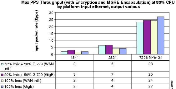
Figure 16 and Figure 17show the throughput of the selected spoke router platforms in terms of bits per second and packets per second. The purpose of this measurement is to compare the capacities of the three platforms.
Figure 16 Mbps Throughput By Platform At 80% CPU Occupancy
Figure 17 PPS Throughput By Platform At 80% CPU Occupancy
Tunnel Overhead for Idle Tunnels
The test results indicate that idle or very low traffic spoke-to-spoke tunnels do not consume significant CPU resources. Table 11 lists the data collected with various numbers of spoke-to-spoke tunnels active but passing minimal traffic. For 100 spoke-to-spoke tunnels, the CPU load is 1 percent or less and the process memory utilization is about 1 MB total or below 10 Kb per tunnel. The CPU load indicates that spoke-to-spoke tunnels can be maintained by IP SLA probes or other background traffic in instances where the path switchover causes unacceptable VoIP quality.
Tunnel Overhead for Active Tunnels
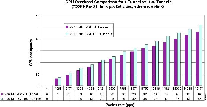
The purpose of measuring the overhead for active tunnels is to estimate the resource utilization of active spoke-to-spoke tunnels when selecting a platform to be a spoke router. Figure 18 compares the CPU occupancy at various packet rates over a single spoke-to-spoke tunnel versus 100 spoke-to-spoke tunnels. The result is that 100 active spoke-to-spoke tunnels increases CPU occupancy 10-15 percent compared with the same traffic over a single tunnel. Similar results were observed with the 1841 and 2821 platforms.
Figure 18 CPU Occupancy Comparison
PPS versus BPS
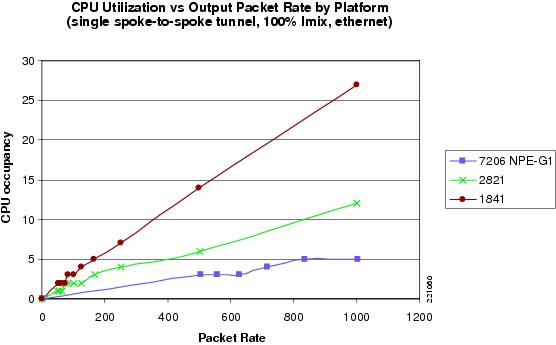
Figure 19 shows the relationship between packet rates and CPU utilization. The CPU utilization increases with the packet rate for a fixed bit rate with variable packet sizes.
Figure 19 CPU Utilization versus Output Packet Rate
Tunnel Setup Load
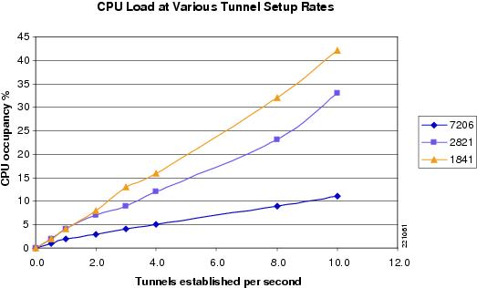
Cisco measured the CPU utilization for spoke-to-spoke tunnel setup processing, which includes NHRP, ISAKMP, and IPsec operations minus the CPU load for sending the same traffic over a single established tunnel. Table 12 and Figure 20 show the peak 5-second CPU occupancy for a burst of tunnel setups at pre-determined rates. The traffic used to trigger each tunnel was 500 packets per second. The data do not factor out the 10-15 percent overhead for transmitting traffic over 100 tunnels versus 1 tunnel; however, the overhead at this packet rate is no more than 1-2 percentage points (see Figure 20).
Figure 20 CPU Occupancy versus Tunnel Setup Rate
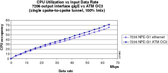
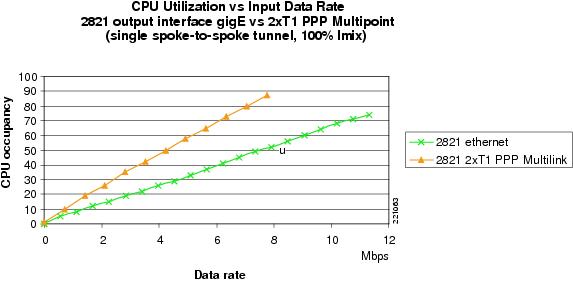
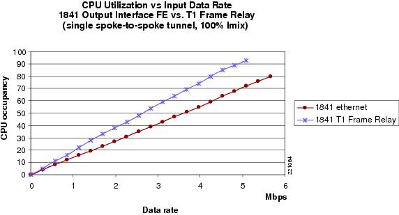
Serial Interface Overhead
The information shown in Figure 21, Figure 22, and Figure 23 helps estimate the overhead associated with the physical interfaces and data link protocols in use on the DMVPN spoke routers.
Figure 21 7206 NPE-G1 GigE versus ATM OC3
Figure 22 2821 GigE versus 2xT1 PPP Multipoint
Figure 23 1841 FE versus T1 Frame Relay
Path Switch Distortion
There is the potential that a small amount of audible distortion can occur when the spoke-to-spoke tunnel is initially established during an active IP phone call. Cisco performed tests to assess the severity of the audible distortion and the ability of Cisco IP phones to conceal the distortion.
Conditions were established similar to the customer DMVPN network, including a variety of SCCP IP phones controlled by a Cisco Unified CallManager cluster. The phones were connected to two different LANs with access to the DMVPN WAN. A network simulator controlled latency between the DMVPN network and the terminating spoke router.
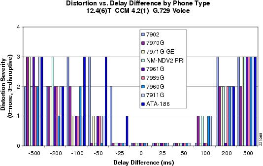
A phone call was made with various latency values simulated for either the spoke-to-spoke path or the spoke-hub-spoke path. A speech sample was played into the originating phone and recorded at the terminating side. When path switch occurred to the spoke-to-spoke path, any resulting audible distortion was rated with a "momentary distortion severity" value on the scale listed in Table 13.
The results of this test (see Figure 24) indicate that little or no audible distortion is present if the difference in latency between the spoke-hub-spoke path and the spoke-to-spoke path is 100 ms or less. Furthermore, if the difference in latency is 50 ms or less, no distortion is audible. For the customer DMVPN network, the latency difference between paths, estimated between 30 ms and 60 ms, does not impact voice quality.
Figure 24 Path Switch Distortion Results
The following results were observed:
•
•
•
•
•
Based on the information in this section, Cisco recommends that you measure the WAN performance using IP SLA probes or another method to confirm that the difference between spoke-hub-spoke and spoke-to-spoke latencies is 100 ms or less. For more information on configuring the IP SLA function, see IP SLA Options Relevant to Voice Over DMVPN.
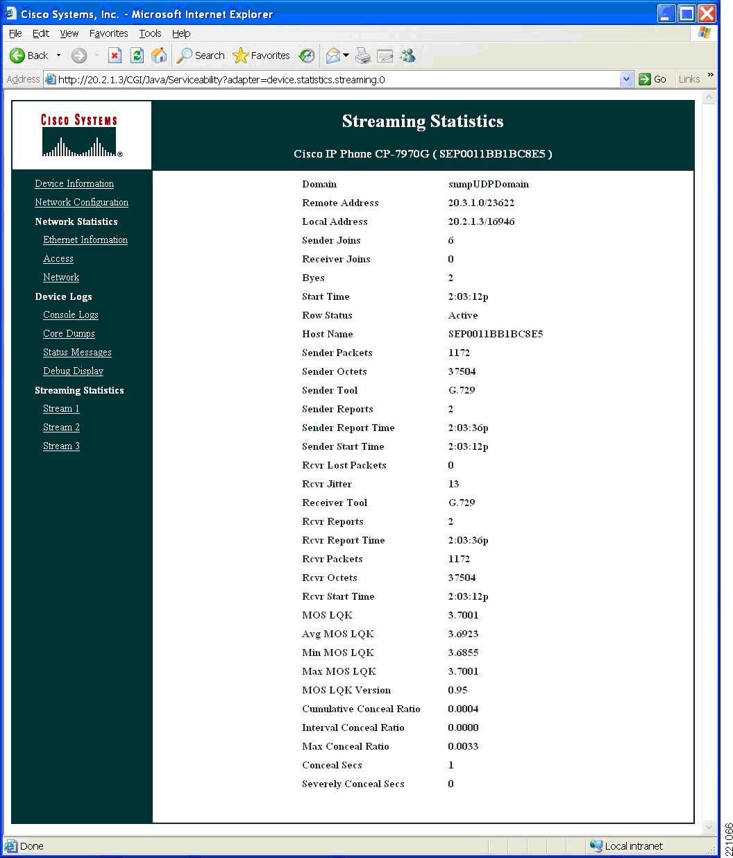
Typical IP Phone Statistics
Cisco IP phones maintain useful statistics related to the current call. Figure 25 shows an example of this information during a typical call between two branch offices over a spoke-to-spoke DMVPN tunnel. This information was obtained using the HTTP interface on a Cisco 7970G IP phone. The same information can be retrieved directly on the phone by pressing the help key twice or selecting call statistics from the setup menu.
Figure 25 IP Phone Statistics Example
Example Configuration Files
This section contains example configuration files for the test bed routers used for the testing reported in this document.
Hub Routers Configuration
Cisco 7206 Hub Router Configuration
The following is the Cisco 7206 DMVPN hub configuration used for this testing:
version 12.4service timestamps debug datetime msecservice timestamps log datetime msecno service password-encryption!hostname 7206-1!boot-start-markerboot system disk2:c7200-adventerprisek9-mz.124-9.T2boot-end-marker!logging buffered 1000000 debuggingno logging consoleenable password lab!no aaa new-model!resource policy!clock timezone EST -5clock summer-time EDT recurringip cef!!ip vrf userrd 10:100!no ip domain lookupip domain name agency.comip multicast-routing!!controller ISA 1/1!interface Tunnel0description dmvpn for user trafficip vrf forwarding userip address 10.2.0.1 255.255.0.0no ip redirectsip mtu 1416no ip next-hop-self eigrp 1ip nhrp authentication myGREkeyip nhrp map multicast dynamicip nhrp map 10.2.0.2 209.165.200.233ip nhrp map multicast 209.165.200.233ip nhrp network-id 99ip nhrp holdtime 300ip nhrp nhs 10.2.0.2ip nhrp max-send 400 every 10ip nhrp registration timeout 75no ip split-horizon eigrp 1load-interval 30delay 1000tunnel source Loopback1tunnel mode gre multipointtunnel key 123456!interface Tunnel1description dmvpn for mgmt trafficip address 10.3.0.1 255.255.0.0no ip redirectsip mtu 1416ip nhrp authentication myGREkeyip nhrp map multicast dynamicip nhrp map multicast 209.165.202.129ip nhrp map 10.3.0.2 209.165.202.129ip nhrp network-id 100ip nhrp holdtime 300ip nhrp nhs 10.3.0.2ip nhrp server-onlyip nhrp max-send 400 every 10ip nhrp registration timeout 75ip nhrp cache non-authoritativeno ip split-horizon eigrp 1load-interval 30delay 1000tunnel source Loopback21tunnel mode gre multipointtunnel key 654321!interface Loopback1description Match with 7609-1 Lo1ip address 209.165.200.234 255.255.255.254!interface Loopback10ip address 209.165.200.249 255.255.255.255!interface Loopback21description Mgmt Data Match with 7609-1 Lo21ip address 209.165.202.130 255.255.255.254!interface GigabitEthernet0/1no ip addressduplex fullspeed 1000media-type rj45no negotiation auto!interface GigabitEthernet0/1.300encapsulation dot1Q 300ip address 10.30.0.1 255.255.255.0!interface GigabitEthernet0/1.301description P2P to 7609-1encapsulation dot1Q 301ip address 10.30.1.1 255.255.255.252!interface GigabitEthernet0/1.3021description P2P to 7609-1encapsulation dot1Q 3021ip address 10.30.21.1 255.255.255.252!interface GigabitEthernet0/2no ip addressshutdown!interface GigabitEthernet0/2.11description Labnet Management and tftp accessencapsulation dot1Q 11ip address 10.11.0.2 255.255.0.0!interface GigabitEthernet0/2.12description ISP Mgmt Trafficencapsulation dot1Q 12ip address 209.165.200.226 255.255.255.248standby 1 ip 209.165.200.225standby 1 preempt delay minimum 120!interface GigabitEthernet0/3no ip addressshutdown!router eigrp 1passive-interface defaultno passive-interface Tunnel0no passive-interface Tunnel1network 10.3.0.0 0.0.255.255network 209.165.200.224 0.0.0.31network 209.165.200.249 0.0.0.0no auto-summary!address-family ipv4 vrf usernetwork 10.2.0.0 0.0.255.255no auto-summaryautonomous-system 1exit-address-family!ip route 0.0.0.0 0.0.0.0 10.30.21.2ip route 209.165.200.233 255.255.255.255 10.30.0.2ip route 209.165.202.129 255.255.255.255 10.30.0.2ip route 209.165.200.240 255.255.0.0 10.30.1.2ip route 209.165.202.136 255.255.255.248 10.30.21.2ip route 209.165.202.144 255.255.0.0 10.30.1.2ip route 209.165.202.152 255.255.0.0 10.30.21.2no ip http serverno ip http secure-server!!ip sla responderlogging alarm informational!control-plane!gatekeepershutdown!line con 0exec-timeout 0 0stopbits 1line aux 0stopbits 1line vty 0 4exec-timeout 0 0password lablogin!scheduler heapcheck process memory processor io checktype lite-chunksntp clock-period 17180039ntp server 10.11.0.1!end7609 IPsec Concentrator Configuration
The following is the Cisco 7609 IPsec concentrator configuration used for this testing:
upgrade fpd autoversion 12.2service timestamps debug datetime msecservice timestamps log datetime msecno service password-encryptionservice counters max age 5!hostname 7609-1!boot system flash disk0:s72033-ipservicesk9_wan-mz.122-18.SXF6logging buffered 1000000 debuggingno logging consoleenable password lab!no aaa new-modelclock timezone EST -5clock summer-time EDT recurringip subnet-zero!ip vrf vpn1rd 10:1!ip vrf vpn2rd 10:2!ip vrf vpn21rd 10:21!ip vrf vpn22rd 10:22!no ip domain-lookupipv6 mfib hardware-switching replication-mode ingressvtp domain mynetvtp mode transparentmls ip multicast flow-stat-timer 9no mls flow ipno mls flow ipv6no mls acl tcam share-globalmls cef error action freeze!crypto engine mode vrf!!redundancymode ssomain-cpuauto-sync running-configspanning-tree mode pvstno spanning-tree optimize bpdu transmissionspanning-tree extend system-iddiagnostic cns publish cisco.cns.device.diag_resultsdiagnostic cns subscribe cisco.cns.device.diag_commandsport-channel per-module load-balance!vlan internal allocation policy ascendingvlan access-log ratelimit 2000!vlan 11,100,301-302,305,311-312,315,3021-3022,3025,3121-3122,3125!! This QOS config is for the ATM link to spoke 2!class-map match-any PCLASS_COS2_SAAmatch dscp 27class-map match-any PCLASS_COS3_SAAmatch dscp 19class-map match-any PCLASS_COS1_SAAmatch dscp 47class-map match-any PCLASS_COS4_SAAmatch dscp 19class-map match-any PCLASS_COS4match not dscp 1class-map match-any QCLASS_COS4match not dscp 1class-map match-any PCLASS_COS2match dscp af31class-map match-any QCLASS_COS3match dscp 19match dscp af21class-map match-any PCLASS_COS3match dscp af21class-map match-any QCLASS_COS2match dscp 27match dscp af31class-map match-any QCLASS_COS1match dscp 47match dscp efclass-map match-any PCLASS_COS1match dscp efclass-map match-any PCLASS_NMmatch access-group 180class-map match-any PCLASS_RPmatch dscp cs6class-map match-any QCLASS_NMmatch dscp cs6match access-group 180class-map match-any Prec_3match ip precedence 3class-map match-any Prec_2match ip precedence 2class-map match-any Prec_1match ip precedence 1class-map match-any Prec_0match ip precedence 0class-map match-any Prec_7match ip precedence 7class-map match-any Prec_6match ip precedence 6class-map match-any Prec_5match ip precedence 5class-map match-any Prec_4match ip precedence 4!!policy-map NMclass PCLASS_RPpolice cir 1500000 bc 150000 be 150000 conform-action set-dscp-transmit cs6 exceed-action set-dscp-transmit cs6 violate-action set-dscp-transmit cs6class PCLASS_NMpolice cir 150000 bc 150000 be 150000 conform-action set-dscp-transmit af21 exceed-action set-dscp-transmit af21 violate-action set-dscp-transmit af21policy-map COS2class PCLASS_COS2police cir 45000000 bc 450000 be 450000 conform-action set-dscp-transmit af31 exceed-action set-dscp-transmit af32 violate-action set-dscp-transmit af32policy-map COS3class PCLASS_COS3police cir 30000000 bc 300000 be 300000 conform-action set-dscp-transmit af21 exceed-action set-dscp-transmit af22 violate-action set-dscp-transmit af22policy-map WAN_150Mclass QCLASS_NMbandwidth remaining percent 10random-detect dscp-basedrandom-detect dscp 18 100 200 10random-detect dscp 48 200 300 10service-policy NMclass QCLASS_COS1priority 60000class QCLASS_COS2bandwidth remaining percent 60random-detect dscp-basedrandom-detect dscp 26 200 300 10service-policy COS2class QCLASS_COS3bandwidth remaining percent 30random-detect dscp-basedrandom-detect dscp 18 200 300 10service-policy COS3policy-map COS4class PCLASS_COS4police cir 15000000 bc 150000 be 150000 conform-action set-dscp-transmit default exceed-action set-dscp-transmit default violate-action set-dscp-transmit default!!crypto keyring vpn22local-address Loopback22pre-shared-key address 0.0.0.0 0.0.0.0 key 123456crypto keyring vpn21local-address Loopback21pre-shared-key address 0.0.0.0 0.0.0.0 key 123456crypto keyring vpn2local-address Loopback2pre-shared-key address 0.0.0.0 0.0.0.0 key 123456crypto keyring vpn1local-address Loopback1pre-shared-key address 0.0.0.0 0.0.0.0 key 123456!crypto isakmp policy 1encr 3desauthentication pre-sharegroup 2crypto isakmp keepalive 60crypto isakmp profile vpnprof2vrf vpn2keyring vpn2match identity address 0.0.0.0local-address Loopback2crypto isakmp profile vpnprof1vrf vpn1keyring vpn1match identity address 0.0.0.0local-address Loopback1crypto isakmp profile vpnprof21vrf vpn21keyring vpn21match identity address 0.0.0.0local-address Loopback21crypto isakmp profile vpnprof22vrf vpn22keyring vpn22match identity address 0.0.0.0local-address Loopback22!crypto ipsec security-association idle-time 720!crypto ipsec transform-set 3DES esp-3des esp-sha-hmacmode transport!crypto dynamic-map dyn-mgre2 10set transform-set 3DESset isakmp-profile vpnprof2!crypto dynamic-map dyn-mgre1 10set transform-set 3DESset isakmp-profile vpnprof1!crypto dynamic-map dyn-mgre21 10set transform-set 3DESset isakmp-profile vpnprof21!crypto dynamic-map dyn-mgre22 10set transform-set 3DESset isakmp-profile vpnprof22!!crypto map mgre2 local-address Loopback2crypto map mgre2 200 ipsec-isakmp dynamic dyn-mgre2!crypto map mgre1 local-address Loopback1crypto map mgre1 200 ipsec-isakmp dynamic dyn-mgre1!crypto map mgre22 local-address Loopback22crypto map mgre22 200 ipsec-isakmp dynamic dyn-mgre22!crypto map mgre21 local-address Loopback21crypto map mgre21 200 ipsec-isakmp dynamic dyn-mgre21!!!interface Loopback1description Match with HUB 7206-1ip address 209.165.200.234 255.255.255.254!interface Loopback2description Match with HUB 7206-2ip address 209.165.200.233 255.255.255.254!interface Loopback21description ISP Mgmt Match with HUB 7206-1ip address 209.165.202.130 255.255.255.254!interface Loopback22description ISP Mgmt Match with HUB 7206-2ip address 209.165.202.129 255.255.255.254!interface GigabitEthernet1/0/1description VPN SPA Inside Interfaceswitchportswitchport trunk encapsulation dot1qswitchport trunk allowed vlan 1,311,312,1002-1005,3121,3122switchport mode trunkmtu 9216no ip addressflowcontrol receive onflowcontrol send offspanning-tree portfast trunk!interface GigabitEthernet1/0/2description VPN SPA Outside Interfaceswitchportswitchport trunk encapsulation dot1qswitchport trunk allowed vlan 1,1002-1005switchport mode trunkmtu 9216no ip addressflowcontrol receive onflowcontrol send offspanning-tree portfast trunk!interface ATM4/0/0no ip addressload-interval 30!interface ATM4/0/0.1 point-to-pointip address 10.99.0.2 255.255.255.252no ip redirectscrypto engine subslot 1/0pvc 1/40cbr 149760encapsulation aal5snapservice-policy out WAN_150M!!interface GigabitEthernet5/1description WAN interface to spokesswitchportswitchport trunk encapsulation dot1qswitchport trunk allowed vlan 100switchport mode trunkno ip addressload-interval 30spanning-tree portfast trunk!interface GigabitEthernet5/2description P2P vlans to 7200 hubsswitchportswitchport trunk encapsulation dot1qswitchport trunk allowed vlan 11,301,302,3021,3022switchport mode trunkno ip addressload-interval 30media-type rj45spanning-tree portfast trunk!interface GigabitEthernet6/1no ip addressload-interval 30shutdownspanning-tree portfast trunk!interface GigabitEthernet6/2no ip addressshutdown!interface GigabitEthernet6/3no ip addressshutdown!interface GigabitEthernet6/4no ip addressshutdown!interface GigabitEthernet6/5no ip addressshutdown!interface GigabitEthernet6/6no ip addressshutdown!interface GigabitEthernet6/7no ip addressshutdown!interface GigabitEthernet6/8no ip addressshutdown!interface Vlan1no ip addressshutdown!interface Vlan11ip address 10.11.0.20 255.255.0.0!interface Vlan100ip address 209.165.201.10 255.255.255.224crypto engine subslot 1/0!interface Vlan301ip vrf forwarding vpn1ip address 10.30.1.2 255.255.255.252load-interval 30!interface Vlan302ip vrf forwarding vpn2ip address 10.30.2.2 255.255.255.252load-interval 30!interface Vlan311description private vlan for VPN-SPA useip vrf forwarding vpn1ip address 10.31.1.2 255.255.255.252load-interval 30crypto map mgre1crypto engine subslot 1/0!interface Vlan312description private vlan for VPN-SPA useip vrf forwarding vpn2ip address 10.31.2.2 255.255.255.252load-interval 30crypto map mgre2crypto engine subslot 1/0!interface Vlan3021ip vrf forwarding vpn21ip address 10.30.21.2 255.255.255.252load-interval 30!interface Vlan3022ip vrf forwarding vpn22ip address 10.30.22.2 255.255.255.252load-interval 30!interface Vlan3121description private vlan for VPN-SPA useip vrf forwarding vpn21ip address 10.31.21.2 255.255.255.252load-interval 30crypto engine subslot 1/0!interface Vlan3122description private vlan for VPN-SPA useip vrf forwarding vpn22ip address 10.31.22.2 255.255.255.252load-interval 30crypto engine subslot 1/0!ip classlessip route 0.0.0.0 0.0.0.0 209.165.201.30ip route 209.165.200.241 255.255.255.255 10.99.0.1ip route 209.165.202.137 255.255.255.255 10.99.0.1ip route vrf vpn1 0.0.0.0 0.0.0.0 Vlan311ip route vrf vpn1 209.165.200.234 255.255.255.255 30.1.0.1ip route vrf vpn2 0.0.0.0 0.0.0.0 Vlan312ip route vrf vpn2 209.165.200.233 255.255.255.255 10.30.2.1ip route vrf vpn21 0.0.0.0 0.0.0.0 Vlan3121ip route vrf vpn21 209.165.202.130 255.255.255.255 10.30.21.1ip route vrf vpn22 0.0.0.0 0.0.0.0 Vlan3122ip route vrf vpn22 209.165.202.129 255.255.255.255 10.30.22.1!no ip http server!logging trap debugginglogging facility local2logging 172.18.154.98access-list 180 permit ip host 172.19.64.1 any!!!control-plane!!!dial-peer cor custom!!!alias exec sib show ip interf briefalias exec pol show policy-map int atm 4/0/0.1alias exec pv show policy-map int atm 4/0/0.1 | begin COS1!line con 0exec-timeout 0 0line vty 0 4exec-timeout 0 0password lablogin!!ntp clock-period 17180095ntp server 10.11.0.1no cns aaa enableendSpoke Router Configuration
The following is the Cisco 7206 spoke router configuration used for this testing:
version 12.4service timestamps debug datetime msec localtime show-timezoneservice timestamps log datetime msec localtime show-timezoneno service password-encryption!hostname 7206-6!boot-start-markerboot system disk2:c7200-adventerprisek9-mz.124-9.T2boot-end-marker!logging buffered 1000000 debuggingno logging consoleenable password lab!no aaa new-model!resource policy!clock timezone EST -5clock summer-time EDT recurringip cef!ip vrf userrd 10:100!no ip domain lookupip domain name agency.com!class-map match-any PCLASS_COS2_SAAmatch dscp 27class-map match-any PCLASS_COS3_SAAmatch dscp 19class-map match-any PCLASS_COS1_SAAmatch dscp 47class-map match-any PCLASS_COS4_SAAmatch dscp 19class-map match-any PCLASS_COS4match not dscp 1class-map match-any QCLASS_COS4match not dscp 1class-map match-any PCLASS_COS2match dscp af31class-map match-any QCLASS_COS3match dscp 19match dscp af21class-map match-any PCLASS_COS3match dscp af21class-map match-any QCLASS_COS2match dscp 27match dscp af31class-map match-any QCLASS_COS1match dscp 47match dscp efclass-map match-any PCLASS_COS1match dscp efclass-map match-any PCLASS_NMmatch access-group 180class-map match-any PCLASS_RPmatch dscp cs6class-map match-any QCLASS_NMmatch dscp cs6match access-group 180class-map match-any Prec_3match ip precedence 3class-map match-any Prec_2match ip precedence 2class-map match-any Prec_1match ip precedence 1class-map match-any Prec_0match ip precedence 0class-map match-any Prec_7match ip precedence 7class-map match-any Prec_6match ip precedence 6class-map match-any Prec_5match ip precedence 5class-map match-any Prec_4match ip precedence 4!!policy-map remarkclass Prec_0set ip dscp defaultclass Prec_1set ip dscp af21class Prec_2set ip dscp af21class Prec_3set ip dscp af31class Prec_4set ip dscp af31class Prec_5set ip dscp efclass Prec_6set ip dscp af21class Prec_7set ip dscp af21policy-map NMclass PCLASS_RPpolice cir 1500000 bc 150000 be 150000conform-action set-dscp-transmit cs6exceed-action set-dscp-transmit cs6class PCLASS_NMpolice cir 150000 bc 150000 be 150000conform-action set-dscp-transmit af21exceed-action set-dscp-transmit af21policy-map COS1class PCLASS_COS1police cir 60000000 bc 600000conform-action set-dscp-transmit efexceed-action dropclass PCLASS_COS1_SAAset dscp efpolicy-map COS2class PCLASS_COS2police cir 45000000 bc 450000conform-action set-dscp-transmit af31exceed-action set-dscp-transmit af32class PCLASS_COS2_SAAset dscp af31policy-map COS3class PCLASS_COS3police cir 30000000 bc 300000conform-action set-dscp-transmit af21exceed-action set-dscp-transmit af22class PCLASS_COS3_SAAset dscp af21policy-map WAN_150Mclass QCLASS_NMbandwidth remaining percent 10random-detect dscp-basedrandom-detect dscp 18 100 200 10random-detect dscp 48 200 300 10service-policy NMclass QCLASS_COS1priority 60000service-policy COS1class QCLASS_COS2bandwidth remaining percent 60random-detect dscp-basedrandom-detect dscp 26 200 300 10service-policy COS2class QCLASS_COS3bandwidth remaining percent 30random-detect dscp-basedrandom-detect dscp 18 200 300 10service-policy COS3policy-map COS4class PCLASS_COS4police cir 15000000 bc 150000conform-action set-dscp-transmit defaultexceed-action set-dscp-transmit defaultclass PCLASS_COS4_SAAset dscp default!!crypto keyring testpre-shared-key address 0.0.0.0 0.0.0.0 key 123456!crypto isakmp policy 1encr 3desauthentication pre-sharegroup 2crypto isakmp keepalive 60 periodiccrypto isakmp profile vpn1keyring testmatch identity address 0.0.0.0crypto isakmp profile vpn2keyring testmatch identity address 0.0.0.0!!crypto ipsec transform-set 3DES esp-3des esp-sha-hmacmode transport!crypto ipsec profile vpnprof1set security-association idle-time 720set transform-set 3DES!crypto ipsec profile vpnprof2set security-association idle-time 720set transform-set 3DES!!!!!!interface Tunnel0bandwidth 1000ip vrf forwarding userip address 10.2.2.2 255.255.0.0no ip redirectsip mtu 1416ip nhrp authentication myGREkeyip nhrp map 10.2.0.2 209.165.200.233ip nhrp map multicast 209.165.200.233ip nhrp network-id 99ip nhrp holdtime 300ip nhrp nhs 10.2.0.2ip nhrp cache non-authoritativedelay 1000tunnel source Loopback0tunnel mode gre multipointtunnel key 123456tunnel protection ipsec profile vpnprof1!interface Tunnel1description Mgmt Trafficbandwidth 1544ip address 10.3.2.2 255.255.0.0no ip redirectsip mtu 1416ip nhrp authentication myGREkeyip nhrp map 10.3.0.2 209.165.202.129ip nhrp map multicast 209.165.202.129ip nhrp network-id 100ip nhrp holdtime 300ip nhrp nhs 10.3.0.2ip nhrp cache non-authoritativeload-interval 30delay 1000shutdowntunnel source Loopback1tunnel mode gre multipointtunnel key 654321tunnel protection ipsec profile vpnprof2!interface Loopback0ip address 209.165.200.241 255.255.255.255!interface Loopback1ip address 209.165.202.137 255.255.255.255shutdown!interface Loopback10ip address 209.165.200.250 255.255.255.255!interface GigabitEthernet0/1no ip addressshutdown!interface GigabitEthernet0/2no ip addressduplex fullspeed 1000media-type rj45no negotiation auto!interface GigabitEthernet0/2.11description Labnet Management and tftp accessencapsulation dot1Q 11ip address 10.11.0.23 255.255.0.0!interface GigabitEthernet0/2.202encapsulation dot1Q 202ip vrf forwarding userip address 192.168.2.1 255.255.255.0!interface GigabitEthernet0/3no ip addressshutdown!interface ATM1/0no ip addressload-interval 30no atm ilmi-keepalive!interface ATM1/0.1 point-to-pointip address 10.99.0.1 255.255.255.252no ip redirectsno snmp trap link-statuspvc 1/40cbr 149760encapsulation aal5snapservice-policy output WAN_150M!!router eigrp 1passive-interface defaultno passive-interface Tunnel0no passive-interface Tunnel1network 10.3.0.0 0.0.255.255no auto-summary!address-family ipv4 vrf usernetwork 10.2.0.0 0.0.255.255network 192.168.2.0 0.0.0.255no auto-summaryautonomous-system 1exit-address-family!ip route 0.0.0.0 0.0.0.0 10.99.0.2no ip http serverno ip http secure-server!ip sla responderlogging alarm informationalaccess-list 100 deny ip any host 239.192.240.1 logaccess-list 180 permit ip host 172.19.64.1 any!control-plane!gatekeepershutdown!line con 0exec-timeout 0 0transport preferred nonestopbits 1line aux 0stopbits 1line vty 0 4exec-timeout 0 0password lablogin!scheduler allocate 20000 1000ntp clock-period 17179989ntp server 10.11.0.1!endMGCP Gateway and SRST Router Configuration
The following is the Cisco 3845 MGCP gateway and SRST configuration used for this testing:
version 12.4service timestamps debug datetime msecservice timestamps log datetime msecno service password-encryption!hostname 3825-2!boot-start-markerboot system flash:c3825-adventerprisek9-mz.124-9.T2boot-end-marker!card type t1 0 0logging buffered 1000000 debuggingenable password lab!no aaa new-model!resource policy!clock timezone EST -5clock summer-time EDT recurringnetwork-clock-participate wic 0ip cef!!no ip dhcp use vrf connectedip dhcp excluded-address 192.168.2.1 192.168.2.99!ip dhcp pool 0network 192.168.2.0 255.255.255.0option 150 ip 192.168.1.11default-router 192.168.2.1dns-server 192.168.1.11domain-name agency.com!!no ip domain lookupip domain name agency.com!!isdn switch-type primary-nivoice-card 0no dspfarm!!applicationglobalservice alternate DEFAULT!controller T1 0/0/0framing sfclock source internallinecode amipri-group timeslots 1-24 service mgcp!controller T1 0/0/1framing sfclock source internallinecode amicablelength short 133pri-group timeslots 1-21,24 service mgcp!!!!!!interface GigabitEthernet0/0ip address 192.168.2.2 255.255.255.0duplex autospeed automedia-type rj45no keepalive!interface GigabitEthernet0/1ip address 10.11.0.10 255.255.0.0duplex autospeed automedia-type rj45no keepalive!interface Serial0/0/0:23no ip addressencapsulation hdlcisdn switch-type primary-4essisdn protocol-emulate networkisdn incoming-voice voiceisdn bind-l3 ccm-managerno cdp enable!interface Serial0/0/1:23no ip addressencapsulation hdlcisdn switch-type primary-4essisdn protocol-emulate networkisdn incoming-voice voiceisdn bind-l3 ccm-managerno cdp enable!router eigrp 1network 192.168.2.0 0.0.0.255no auto-summary!ip route 0.0.0.0 0.0.0.0 192.168.2.1ip route 64.0.0.0 255.0.0.0 10.11.0.1ip route 172.0.0.0 255.0.0.0 10.11.0.1!!ip http serverno ip http secure-server!ip sla responder!!!!!!control-plane!!!voice-port 0/0/0:23!voice-port 0/1/0!voice-port 0/1/1!voice-port 0/1/2!voice-port 0/1/3!voice-port 0/0/1:23!voice-port 1/0/0!voice-port 1/0/1!voice-port 1/0/2!voice-port 1/0/3!voice-port 1/0/4!voice-port 1/0/5!voice-port 1/0/6!voice-port 1/0/7!voice-port 1/0/8!voice-port 1/0/9!voice-port 1/0/10!voice-port 1/0/11!voice-port 1/0/12!voice-port 1/0/13!voice-port 1/0/14!voice-port 1/0/15!ccm-manager fallback-mgcpccm-manager redundant-host 192.168.1.12ccm-manager mgcpccm-manager music-on-holdccm-manager config server 192.168.1.11ccm-manager config!mgcpmgcp call-agent 192.168.1.11 2427 service-type mgcp version 0.1mgcp dtmf-relay voip codec all mode out-of-bandmgcp rtp unreachable timeout 1000 action notifymgcp modem passthrough voip mode nsemgcp package-capability rtp-packageno mgcp package-capability res-packagemgcp package-capability sst-packageno mgcp package-capability fxr-packagemgcp package-capability pre-packageno mgcp timer receive-rtcpmgcp sdp simplemgcp fax t38 gateway forcemgcp rtp payload-type g726r16 static!mgcp profile default!dial-peer voice 999011 potsservice mgcpappport 0/1/1!dial-peer voice 999012 potsservice mgcpappport 0/1/2!dial-peer voice 999013 potsservice mgcpappport 0/1/3call-manager-fallbacksecondary-dialtone 9max-conferences 12 gain -6transfer-system full-consultip source-address 192.168.2.2 port 2000max-ephones 336max-dn 500system message primary SRST Mode on 3825-2system message secondary SRST Mode on 3825-2moh flash:music-on-hold.au!!line con 0exec-timeout 0 0stopbits 1line aux 0stopbits 1line vty 0 4exec-timeout 0 0password labloginline vty 5 20exec-timeout 0 0password lablogin!scheduler allocate 20000 1000ntp clock-period 17179716ntp server 11.0.0.1!endReferences
This document references the following related documents:
•
•
•
•
•
•
•
•
•