Table Of Contents
IP Video Surveillance 1.0 Solution Overview
IP Video Surveillance Components
Quality of Service Design Considerations
Branch PIN Design Considerations
WAN/MAN PIN Design Considerations
Campus PIN Design Considerations
Technical Assistance Center (TAC
Cisco Video Surveillance Solution
Cisco 2800/3800 ISR IP Video Surveillance Network Modules
Solution Overview and Best Practices
General Best Practices Guidelines
IP Video Surveillance 1.0 Solution Overview
Contents
This document summarizes high-level design recommendations and best practices to implement IP video surveillance on the enterprise network infrastructure. In some instances, existing network equipment and topologies have the necessary configuration and performance characteristics to support high-quality IP video surveillance. In other instances, network hardware might require upgrading or reconfiguration to support increased bandwidth needed to support video. Quality of service (QoS) techniques are important for any design because video has similar—in some instances, more stringent—requirements than VoIP for loss, latency and jitter.
IP video surveillance is a part of the medianet—a network initiative to incorporate all forms of video on the enterprise network. IP-based Video Surveillance is one of the four components of the medianet. These components consist of the following:
•
TelePresence Network System
•
•
•
This solution overview focuses on IP video surveillance while other overviews focus on the other three solutions. Not all forms of video on the enterprise network have the same requirements, given the diversity of transport techniques and user interfaces to the video feeds.
IP Video Surveillance Components
There are five components of all IP-based video surveillance solution. These are as follows:
•
•
•
•
•
The camera component is addressed by the Cisco Video Surveillance IP Camera, analog cameras attached to encoders, analog gateway network modules for the integrated services router, or third-party IP surveillance cameras.
The video management software is addressed by the Cisco Video Surveillance Manager (VSM) suite of software. This software runs on one or more standalone, Linux-based servers or on a Cisco Integrated Services Router (ISR) Series Video Management and Storage System network module.
The storage component is aligned with either the Data Center Architecture and the Cisco Video Surveillance Storage System, or with off-the-shelf iSCSI servers for archiving and storage of video feeds.
The network component is the enterprise network—the medianet. The primary focus of this document is to reference the existing Solution Reference Network Design baselines of Branch Office, Campus, WAN, and Metro Area Networks while building on this base of knowledge with IP video surveillance requirements, best practices, and design recommendations.
The IP video surveillance component of the medianet is integrated with the Places in the Network (PIN) architecture. along with the companion video components of the medianet.
Supporting Designs
Implementing IP video surveillance on an existing network is designed to overlay non-disruptively on other core Cisco PIN Architecture design elements. These include the following:
•
•
•
•
Each is summarized in the subsequent descriptions.
Quality of Service Design Considerations
QoS design is addressed in the Enterprise QoS Solution Reference Network Design Guide Version 3.3 available at
http://www.cisco.com/application/pdf/en/us/guest/netsol/ns432/c649/ccmigration_09186a008049b062.pdf
and should be considered a fundamental consideration for implementing video on any corporate network. Both voice and video are tolerant of some packet loss, latency, and jitter between the video end points; however, video is typically less tolerant to loss than voice over IP (VoIP). Depending on the type of video feed, the disruption of video quality might be evident for much longer periods of time than with VoIP.
Branch PIN Design Considerations
The Branch Architecture design collateral is organized under the Design Zone for Branch, which can be found at:
http://www.cisco.com/en/US/netsol/ns816/networking_solutions_program_home.html
From this web link, there are a number of branch-related PIN design guides which are applicable to implementing a branch router deployment. They include the following:
•
•
•
The integration between IP video surveillance and the Enterprise Branch Architecture is targeted at integration of the Cisco ISR VS network modules. Enabling Branch Architecture services along with the Cisco ISR VS network modules is a key element of IP Video Surveillance 1.0
The Cisco Empowered Branch 4 marketing launch included the Cisco Video EVM-IPS-16A EVM Module featuring analog-to-IP encoding capabilities for existing analog cameras and the Cisco NME-VMSS Module which supports the Cisco Video Surveillance Manager (VSM) suite of software on the network module. The EVM-IPS-16A module is not required if the deployment is with all IP surveillance cameras.
Empowered Branch 4 also includes the Cisco 880 ISRs, which have sufficient performance characteristics to support the various forms of video at a Small Office/Home Office (SOHO) location. Many of the foundation architecture concepts from the Business Ready Teleworker
http://www.cisco.com/application/pdf/en/us/guest/netsol/ns171/c649/ccmigration_09186a008074f24a.pdf
The teleworker or SOHO deployment is applicable for addressing remotely located or isolated wired-IP cameras which in turn can be managed by a central or branch Video Surveillance Manager deployment. Video Surveillance Operations Manager viewing stations—PCs running an Active-X enabled web browser—may also be located at extranet or remote locations to allow physical security staff or law enforcement agencies to view live or archived video.
Application Networking Services (ANS), such as Wide Area Application Services (WAAS), are a key element given that the transport for IP video surveillance viewing stations is TCP-based.
WAN/MAN PIN Design Considerations
The WAN/MAN PIN Architecture reference is:
http://www.cisco.com/en/US/netsol/ns817/networking_solutions_program_home.html
There are several design guides within the Design Zone for WAN/MAN that describe foundation architectures for deploying IP video surveillance. The integration between IP video surveillance and the WAN/MAN Architecture is targeted at QoS, NetFlow, Network Based Application Recognition (NBAR), Ethernet access, Performance Routing (PfR) and implementing IP Security (IPSec) technologies to enable privacy, integrity, and authenticity of IP video surveillance data through encryption. Because of the focus on the Cisco ISR VS network modules in branch routers, the design guidance provided here relies heavily on integration of the WAN/MAN PIN.
If the branch office locations are implemented over a public network, the Dynamic Multipoint VPN (DMVPN) Design Guide provides important information on encrypting data between branch, SOHO, and central office locations. Because of the requirements for availability and selecting the optimal path among redundant links, the Transport Diversity: Performance Routing (PfR) Design Guide is also a key element in a successful deployment. Video requires much higher bandwidth than is required for a VoIP and data enabled branch location and the Ethernet Access for Next Gen Metro and Wide Area Networks might be applicable when implementing the branch office over a Metro Ethernet deployment or an Multiprotocol Label Switching (MPLS) Layer-2 pseudowire. Also applicable is the Next Generation Enterprise MPLS VPN-Based MAN Design and Implementation Guide.
Campus PIN Design Considerations
The Campus PIN Architecture reference is
http://www.cisco.com/en/US/netsol/ns815/networking_solutions_program_home.html
There are several design guides within this Design Zone for Campus that can provide guidance to the network manager in designing a campus medianet. These include the following:
•
•
•
•
The existing Cisco Video Surveillance Manager Solutions Reference Guide can be found at the following URL:
http://www.cisco.com/en/US/prod/collateral/vpndevc/ps6918/ps9145/ps9152/design_guide_c07-462879.pdf
That publication references the application recognition services, QoS marking, and design requirements for a campus-based Video Surveillance Manager deployment at a campus or central location. That existing design guide will be superseded by a IP Video Surveillance 1.0 design guide at a future date.
The integration between IP video surveillance and Campus PIN Architecture is a requirement because most IP network cameras support Power over Ethernet (PoE). PoE is important to facilitate installation of these cameras as a single Category 5 Ethernet cable can provide both Ethernet connectivity and power-reducing installation costs. The Cisco IP cameras support Cisco Discovery Protocol (CDP) and Simple Network Management Protocol (SNMP), which together help to simplify provisioning and device management.
In the campus, QoS marking at both Layer 2—class of service (CoS)—and Layer 3—Differentiated Services Code Point (DSCP)—can be enabled in the switching infrastructure to enhance the usability and quality of the video feeds.
The cameras, servers, and encoders can be deployed on separate VLANs to provide isolation at Layer 2 and transported over the WAN with Layer-3 isolation over an MPLS virtual private network (VPN).
Data Center PIN Architecture
The Data Center PIN Architecture reference links can be found within the Design Zone for Data Centers at the following URL:
http://www.cisco.com/en/US/netsol/ns743/networking_solutions_program_home.html
The integration between IP video surveillance and the Data Center PIN Architecture intersects notably at the storage requirements of an IP video surveillance system. An archive is a collection of video data. The video source, a feed from a camera or encoder, can be stored in multiple locations and viewed at a later time. Archives are either one-time (where the archive recording stops at a specified date and time) or continuous loop (where the archive continuously records). Loop archives reuse the disk space. Archives may also be scheduled to begin at a certain date and time and run using a recurring schedule.
The storage requirements for video archives can be substantial. For example, a High Definition (HD) surveillance camera recording at a rate of 10 motion JPEG frames per second with a resolution of 1600 x 1200 pixels can require up to 1GB of disk storage per hour. Retention of this archive for days or weeks, combined with a deployment of a hundred cameras will consume vast amounts of storage.
The Cisco Video Surveillance Manager Solutions Reference Guide addresses at a functional level the way in which the storage subsystem of the Cisco Video Surveillance Media Server can augment internal storage with direct-attached storage and storage area networks (SANs). Additionally, the Cisco ISR Series Video Management and Storage System network module supports an iSCSI interface for local storage in the branch office.
Technical Assistance Center (TAC
Technical Assistance Center (TAC) Technical Tips are a valuable sources of configuration examples for the technologies deployed in this design guide. Please refer to the Technical Tip section after logging on the Cisco TAC cisco.com page at http://www.cisco.com/tac.
Solution Description
In this section the, Cisco Video Surveillance Solution is described at a functional level given a deployment of the components on standalone workstations and appliances. In addition, the functional components are mapped to an implementation using the Cisco 2800/3800 ISR IP Video Surveillance Network Modules. The Cisco Video Surveillance Manager software is a common code base that is ported to run on the network module.
Cisco Video Surveillance Solution
The Cisco Video Surveillance Solution relies on an IP network infrastructure to link all components. The designs of a highly available hierarchical network have been proven and tested for many years and allow applications to converge on an intelligent and resilient infrastructure.
Cisco offers a unique approach to moving different proprietary systems to a common IP backbone. This approach leverages other Cisco technologies, such as network security, routing, switching, network management, and wireless. Video from IP cameras can now be truly converged into a robust network environment with the intelligence and flexibility provided by the Cisco infrastructure.
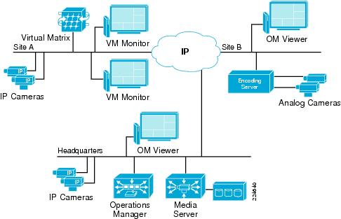
Figure 1 shows the Cisco Video Surveillance Manager solution using an Intelligent IP infrastructure as a transport.
Figure 1 Cisco Video Surveillance Solution
Solution Components
The following components make up the Cisco Video Surveillance Solution:
•
•
•
•
•
Cisco 2800/3800 ISR IP Video Surveillance Network Modules
In addition to the standalone dedicated implementation of the Cisco Video Surveillance Solution on Linux servers, the Cisco 2800 and Cisco 3800 ISRs support the necessary components of the solution to implement a self-contained instance at the branch location.
The Cisco Video Management and Storage System (VMSS) Network Module implements the Operatons Manager and Media Server functions for the branch. It supports IP based video cameras as well as analog cameras attached to the Analog Video Gateway Module.
The Analog Video Gateway Module installed in the Cisco ISR branch router provides support for analog cameras, analog Pan Tilt Zoom (PTZ), alarm input and control relay output. It supports up to 16 analog cameras. This module supports RS-485 on two serial interfaces, which controls analog Pan Tilt Zoom (PTZ). The module also supports event alerts by way of alarm input and control-relay output serial connections. The Analog Video Gateway Module is optional if these functions are not required.
A branch with all IP cameras and no analog requirments need only the VMSS network module. The NME-VMSS-16 and NME-VMSS-HP16 support up to 16 cameras, the NME-VMSS-HP32 is licensed to support up to 32 cameras.
The Virtual Matrix component is not supported on the Cisco ISR Video Surveillance Modules.
The Operations Manager provides a web-based browser console to configure, manage, display, and control video supported at the branch location. The Operations Manager and the Media Server share the same IP address configured on the logical interface of the Integrated Services Network Module. One or more Cisco Video Surveillance Media Servers are managed through this interface. The Operations Manager web interface is where the physical security administrator configures IP and analog cameras and where video feed archives are secheduled and managed.
In this remote branch location deployment, use of the Cisco VMSS provides efficiency. Traffic only needs to traverse the network when requested by remote viewers. Branch office video remains localized and does not have to traverse wide-area connections unless requested by users. An external iSCSI device is attached to the GigabitEthernet port on the network module in order to supplement the disk storage on the VMSS module.
In this topology, physical security staff at the campus location, a third-party location at an Extranet site, a separate branch, or even a remote teleworker location can configure, manage, and display the VMSS at the branch location. Video requests and video streams are delivered to the viewer via Hypertext Transfer Protocol (HTTP) which uses Transmission Control Protocol (TCP) port 80.
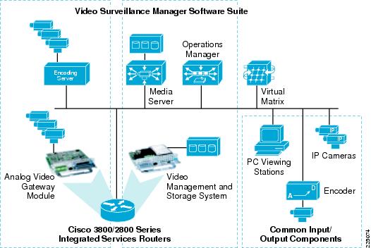
In Figure 2, the Video Surveillance Manager Software Suite components for both the Linux deployment and the Cisco ISR IP Video Surveillance Network Module deployment are shown.
Figure 2 Video Surveillance Manager Software Suite Components
At the branch location, the Analog Video Gateway Module provides a similar function to the encoding server. The Media Server and Operations Manager, along with storage, are supported on the VMSS network module. The Virtual Matrix function is not supported on the Cisco ISR Video Surveillance Modules. The IP cameras, analog cameras attached to dedicated IP encoders, and the PCs used as viewing stations are common to both implementations.
Solution Benefits
Video surveillance is a key component of the safety and security procedures of many organizations. It provides real-time monitoring of the environment, people, and assets, and provides a recorded archive for investigative purposes. The benefits of Cisco's Video Surveillance Solution include the following:
•
•
•
•
•
•
•
•
Solution Scope
This publication will be extended and updated over time as capabilities expand the addressable market. The associated design guide focuses on the following:
•
•
•
•
•
•
•
•
•
•
•
•
Other features that were not evaluated for initial revision of the associated design guide include the following:
•
•
•
•
Solution Overview and Best Practices
This section presents a high-level overview of an IP Video Surveillance deployment to give the reader a quick reference as to the capabilities of this solution. The associated design guide will then go into detail on planning, design, product selection, and implementation of an IP Video Surveillance deployment.
Deployment Model
A typical IP Video Surveillance deployment in an enterprise network consists of one or more campus locations running Cisco Video Surveillance Media Server, Video Surveillance Operations Manager, and Video Surveillance Virtual Matrix on an Intel-based Linux Enterprise Server operating system. Deployment on standalone hardware is targeted at locations with more than 32 video surveillance cameras.
Branches which have a requirement for 1-to-32 video surveillance cameras can incorporate the Cisco ISR Video Surveillance Modules to provide the Media Server and Operations Manager functionality in a network module form factor. Optionally, an Analog Video Gateway Module can be installed to support legacy analog cameras.
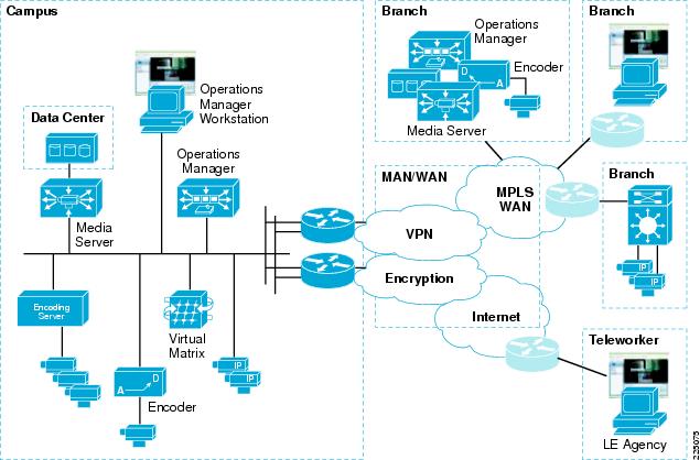
Branch offices and teleworker locations may view and administer the video surveillance system—as may external organizations connected either through an Extranet or the public Internet by way of a global IP connectivity and a web browser. Figure 3 illustrates the topology and application services deployed in an enterprise-wide implementation of IP-based video surveillance.
Figure 3 Video Surveillance Solution Master Architecture Diagram
The branch locations are connected to the enterprise campus by WAN technologies, including Metro Ethernet, private line, the public Internet, or a Layer-2 or Layer-3 MPLS VPN deployment. With a Layer-2 MPLS deployments (Pseudowire), IP cameras may be Ethernet-attached to a remote switch and have images transported through the carrier network and provisioned and managed by the Operations Manager at either a branch location or a central location. Branches attached by way of a Layer-3 MPLS network, leased line, or over the Internet can support viewing stations and IP cameras that can be managed by either the campus or branch deployment.
Cisco technologies such as DMVPN can be overlaid onto the WAN transport to provide data privacy and authentication by way of IPSec encryption. To ensure prioritization of voice, video, and mission critical applications over the WAN, QoS is deployed on the WAN. Where multiple WAN links exist, PfR can be enabled to provide intelligent path selection and the ability to route around brownouts and transient failures, thereby enhancing what can be provided by traditional routing protocols such as Enhanced Internal Gateway Routing Protocol (Enhanced IGRP).
The decision as to whether a specific environment should implement the Cisco ISR Video Surveillance Modules at a branch location and archive data at the branch—or provision cameras off the campus implementation of the Cisco Video Surveillance Manager—depends on the number of cameras, the resolution, frame or bit rate of the camera, quality factors of the cameras, and the cost and availability of bandwidth at the remote locations. In cases where implementing cameras is the only requirement, it may be practical to transport the camera feeds across the WAN for archiving. However, in most deployments, local storage is necessary due to the bandwidth required and the costs associated with this bandwidth.
Solution Characteristics
Table 1 represents the general solution characteristics for an IP video surveillance deployment
General Best Practices Guidelines
Table 2 presents a list of best practices that have been established through a combination of design experience, scalability and performance evaluation, and internal Cisco trials.
General Solution Caveats
Table 3 presents a list of caveats for the solution described in this solution overview.
References
Refer to the medianet documents at: