Table Of Contents
Branch Network Design Considerations
Distributed VPN Connectivity Designs
Centralized VPN Connectivity Designs
Branch Design Considerations
Branch Network Design Considerations
When designing the network to support one or more Mediators within a branch location, the design engineer must first determine the energy management solution deployment model. As mentioned previously, installations involving a managed service provider (MSP) partner often require VPN access to and from the Mediators within the branch back to the MSP network. In this deployment model, the VPN connectivity may be provisioned directly to each branch, referred to as distributed VPN connectivity. Alternatively, VPN connectivity may be centrally provisioned at a campus location and access allowed through the enterprise network to each branch. Each of these options is discussed separately.
Distributed VPN Connectivity Designs
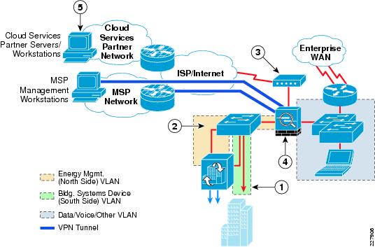
For small energy management deployments involving only a handful of locations, provisioning separate VPN connectivity to each branch location may be acceptable. VPN access can take the form of a dedicated Catalyst switch separated from the existing branch IT network through a Cisco ASA 5500 Series Security Appliance that provides both VPN termination and stateful firewalling. An example of this design for a medium-sized branch site is shown in Figure 6-1.
Figure 6-1 Branch Design with Dedicated Switch and ASA 5500 Security Appliance
The following describes the numbers in Figure 6-1:
•
1—Building systems device VLAN isolated by not trunking it to the dedicated ASA 5500 Security Appliance.
•
•
•
•
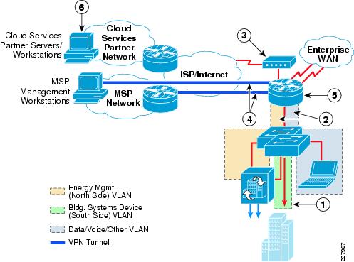
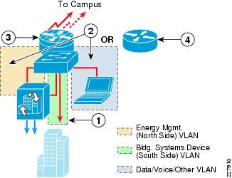
Although this type of implementation provides a high degree of isolation and access control, the duplication of the switch infrastructure, dedicated VPN router, and firewall appliance results in higher hardware and ongoing maintenance costs. The preferred approach is to provision separate VLAN segments on the existing branch Catalyst switch platform for energy management. A single Cisco ISR branch router can provide both the WAN access to the branch from the enterprise campus network, as well as the VPN access from the MSP network (with appropriate software image and licensing). An example of this type of design for a medium-sized branch site is shown in Figure 6-2.
Figure 6-2 Branch Design with VPN Access and Integrated Infrastructure
The following describes the number in Figure 6-2:
•
•
•
•
•
•
In cases where an IPSec VPN provides the enterprise WAN connectivity, an additional VPN tunnel may be provisioned to the MSP network. In the case where private enterprise WAN connectivity is provisioned, a separate Internet connection can be provisioned on the Cisco ISR branch router, as is shown in Figure 6-2. Either CBAC or ZBPF running within the branch ISR router can be used to provide stateful access control between the energy management systems VLANs and the rest of the enterprise network and the MSP. The branch Internet connectivity could also be used to directly support the periodic export of logged data points to a cloud-services partner, as well as allow client PCs access to cloud services such as energy scorecards. However, default routing issues at the branch may limit its applicability. The network administrator may instead choose to backhaul such traffic across the enterprise WAN to the campus Internet edge.
In the designs shown in Figure 6-1 and Figure 6-2, access control should be specified down to the IP addresses and protocols required between the MSP partner and/or cloud-services partner devices and the branch Mediator. Specific protocols required are discussed Chapter 2, "Deployment Models and Information Flows." In small deployments where VPN access is provisioned to each branch, the enterprise customer may completely outsource the management of the energy management solution to the MSP. In such cases, the enterprise customer may not deploy an Energy Management Operations Center (EMOC), as discussed in Chapter 5, "Data Center/Campus Service Module Design Considerations." Therefore, no inbound access from enterprise energy management workstations may be needed. Likewise no outbound access from the mediators to enterprise archiving servers for periodic exporting of logged datapoint information may be needed with a small deployment.
Even with a small deployment, enterprise client PC access within the branch to energy usage data may still be a requirement. As discussed in Chapter 5, "Data Center/Campus Service Module Design Considerations,"access to energy usage data can be accomplished in the following ways:
•
•
•
•
If business needs only require non-real-time access to historical energy usage information, enterprise client PCs may only need access outbound to the Internet in order to reach a cloud services partner energy scorecard server. This can be allowed directly at the branch, or backhauled across the corporate WAN (if a corporate WAN exists within a small deployment) to the Internet edge within the campus. Note that many enterprise organizations backhaul traffic across the corporate WAN to the Internet edge simply to implement a single point of access for all employee traffic to the Internet for monitoring and control purposes, as well as ease of implementing routing tables.
In cases where real-time access to energy usage information is needed, or the enterprise client PCs may need to override setpoints, direct access to the Mediators may be required, although this poses a greater security risk, since the Mediators may be controlling building systems devices. Again, limited access through a hierarchical Mediator deployed within an EMOC provides a more secure and single point of access to the energy management solution. However, in small deployments, if no hierarchical Mediator is deployed within an EMOC, then access may need to be allowed directly between enterprise client PCs and the branch Mediator. Where possible, access should be limited to a subset of PCs, based on IP address, and restricted to the use of secure protocols such as HTTPS. Userids and passwords should be implemented on the Mediator to restrict access as well. The network administrator may consider the deployment of remote access VPN technology on the ASA 5500 Security Appliance or ISR router as an additional security mechanism for enterprise client PC access as well. Note that with the deployment of individual VPN access to each branch, a centralized AAA service is still recommended. However, with small deployments, the enterprise customer may not have a central AAA server. Therefore, individual ASA 5500 and/or ISR routers deployed within each branch may hold local databases for MSP and enterprise client PC access to the energy management solution within that branch.
Comparing both dedicated branch VPN designs shown in Figure 6-1and Figure 6-2, the design shown in Figure 6-2 results in lower hardware and ongoing maintenance costs, but the management and reoccurring costs of an additional VPN connection for each branch location may still prohibit the scaling of this implementation.
Centralized VPN Connectivity Designs
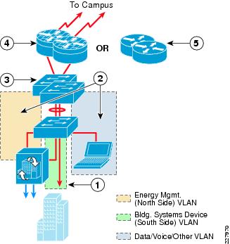
For large energy management solution implementations, centralizing the MSP VPN connectivity to a campus or data center location provides a much more scalable and manageable deployment. The headend design for this type of energy management solution is discussed in Chapter 4, "Internet Edge Design Considerations." Figure 6-3 shows an example of a large branch design for support of the energy management solution that uses the centralized VPN model.
Figure 6-3 Example Large Branch Site Design
The following describes the numbers in Figure 6-3:
•
•
•
•
•
Large branch sites often implement distribution and access-layer switches for scalability, similar to a small campus building design. The distribution layer may consist of a Layer-3 Catalyst 3750 Series switch stack, while the access layer consists of Layer-2 Catalyst 2900 Series switches. In this design, a separate energy management VLAN (north side) and a separate building systems device VLAN (south side) are provisioned on the Layer-2 access switch. The energy management VLAN, along with any data/voice/other VLANs, are trunked to the Layer-3 distribution switch. However, the building system's device VLAN is not trunked, effectively isolating it within the access-layer switch. The only devices connected to the building systems VLAN are the actual building devices that use protocols such as BACnet/IP and Modbus/TCP, as well as the building systems device (south side) interface of the Mediator. With this design, all communications to the building devices occur through the Mediator.
Within the branch, access to and from the Mediator is controlled via ACLs applied to switched virtual interface (SVI) defined for the energy management VLAN on the Layer-3 distribution switch. Access to and from the Mediator from the devices within the MSP network, as well as the enterprise Energy Management Operations Center (EMOC) located within the campus, can further be controlled via the branch router. When stateful firewalling is desired or required, either CBAC or ZBPF can be run on the branch router. Alternatively, stateless access control can be accomplished via ACLs applied on the branch ISR router.
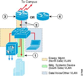
Figure 6-4 shows an example of a medium-sized branch site design for support of the energy management solution.
Figure 6-4 Example Medium Branch Site Design
The following describes the numbers in Figure 6-4:
•
•
•
•
Medium-sized branch sites often consist of just a branch ISR router and a Layer-2 Catalyst 2900 Series switch stack functioning as the access layer. In this design, a separate energy management VLAN (north side) and a separate building systems device VLAN (south side) are again provisioned on the Layer-2 access switch. The energy management VLAN, along with any data/voice/other VLANs, are trunked to a branch ISR router. However, the building systems device VLAN is not trunked, effectively isolating it within the access-layer switch stack. The only devices connected to the building systems VLAN are the actual building devices that use protocols such as BACnet/IP and Modbus/TCP, as well as the building systems device (south side) interface of the Mediator. With this design, all communications to the building devices occur through the Mediator. Example 6-1 shows a partial configuration of a Catalyst 2960 switch with this design.
Example 6-1 Partial Catalyst 2960 Configuration Showing VLANs For Mediator Management and Building System Devices
!interface FastEthernet0/18description CONNECTION TO MEDIATOR MGMT INTERFACEswitchport access vlan 192 ! Mediator management VLAN!interface FastEthernet0/19description CONNECTION TO MEDIATOR BLDG SYSTEMS INTERFACEswitchport access vlan 193 ! Mediator building device VLAN!~interface GigabitEthernet0/1description TRUNK TO ME-WESTRICH-1switchport trunk allowed vlan 1-192,194-4094 ! VLAN 193 not trunked to routerswitchport mode trunksrr-queue bandwidth share 1 30 35 5priority-queue outmls qos trust!Within the branch, access to and from the Mediator is controlled via the branch ISR VLAN interfaces. When stateful firewalling is desired or required, either CBAC or ZBPF can be run on the branch ISR router. Alternatively stateless access control can be accomplished via ACLs applied on the branch ISR router energy management VLAN interface.
Figure 6-5 shows an example of a small branch site design for support of the energy management solution.
Figure 6-5 Example Small Branch Site Design
The following describes the numbers in Figure 6-5:
•
•
•
•
Small branch sites often consist of a branch ISR router in which the Layer-2 switch has been collapsed into the router as a switch module. The overall energy management design is effectively the same as if a standalone Catalyst switch were deployed.
Extending VRFs to the Branch
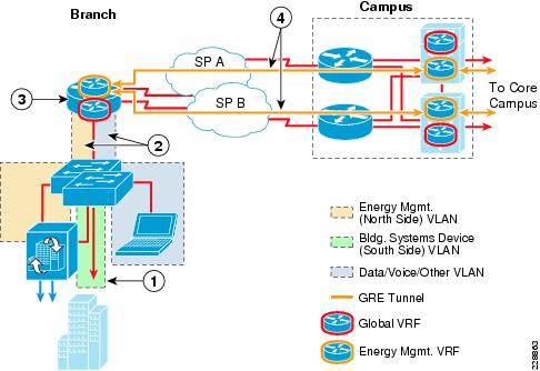
The deployment of network virtualization for energy management systems can provide the additional advantage of path isolation of the energy management solution traffic across the IP network infrastructure. When applied to the branch, an energy management Virtual Routing and Forwarding (VRF) instance is extended into the Layer-3 device. An example of this for the medium branch site design is shown in Figure 6-6.
Figure 6-6 Example of an Energy Management VRF Extended to the Branch
The following steps describe what occurs in Figure 6-6:
•
•
•
•
In this example, the energy management VLAN is defined on the Layer-2 access switch and trunked to the ISR router, where the Layer-3 interface for the energy management VLAN is defined. The VLAN is then mapped to an energy management VRF that is separate from the global VRF which supports the data/voice/other VLANs. Example 6-2 shows a partial configuration of a Cisco 3845 ISR router in this configuration, but with only a single GRE tunnel.
Example 6-2 Partial Branch ISR Router Configuration with VRF Implementation
!ip vrf bin ! Creates Building Infrastructure Network (BIN) VRFrd 192:118!~!interface Loopback2description LOOPBACK INTERFACE FOR BIN GRE TUNNELip address 10.17.252.9 255.255.255.252!interface Tunnel0 ! GRE tunnel extending BIN VRF to the campusdescription VRF FOR MEDIATOR NETWORK TO ME-WESTDIST-1ip vrf forwarding binip address 10.17.192.25 255.255.255.248tunnel source Loopback2tunnel destination 10.17.100.10!interface GigabitEthernet0/0no ip addressload-interval 30duplex autospeed automedia-type rj45!interface GigabitEthernet0/0.182 ! VLAN sub-interface for data network in global VRFdescription Employee PCsencapsulation dot1Q 182ip address 10.18.2.1 255.255.255.0!interface GigabitEthernet0/0.192 ! VLAN sub-interface for Mediator mgmt networkdescription BRANCH MEDIATOR MGMT NETWORKencapsulation dot1Q 192ip vrf forwarding bin ! Places VLAN 192 into the BIN VRFip address 10.17.192.17 255.255.255.248!~!interface Serial3/0 ! WAN interfaceip address 192.168.64.25 255.255.255.252load-interval 30dsu bandwidth 44210max-reserved-bandwidth 100!Because the traffic within the energy management VRF is isolated from traffic in other VRFs, stateful firewalling is not really required within the branch ISR itself. However, inbound and outbound ACLs may still be applied to the energy management VLAN in order to restrict access to the Mediators, if desired. The centralized VPN connectivity from the MSP to all of the enterprise energy management systems, along with the deployment of a separate energy management VRF, can provide complete path isolation of the energy management systems traffic and require only a centralized security policy.
Note
From the branch, the energy management VRF can be extended across the WAN via GRE tunnels. This method is referred to as the VRF-Lite with GRE Tunnel model. GRE tunnels can be defined from the branch ISR router to the Layer-3 distribution switches within the campus WAN Module (discussed in Chapter 3, "Campus Design Considerations"). The GRE tunnels are then mapped to the energy management VRF. These tunnels support both MSP partner VPN management as well as the periodic export of logged data to the Internet via the Campus Partner Extranet Module. Note that other methods of extending VRFs across the WAN exist as well; for example, the mapping of VRFs to an MPLS service. These have not been evaluated for this vision of the design guide.
When deploying a VRF for path isolation of the energy management solution, it is recommended that where possible, enterprise client PC access into the energy management solution should be centralized to one or more strategic locations, such as the EMOC or Partner Extranet Module. In other words, direct connectivity provided within the branch itself from enterprise client PCs to the Mediator should be avoided. Chapter 5, "Data Center/Campus Service Module Design Considerations" discusses how this may be achieved. This may include the use of a data center firewall between the energy management (BIN) VRF and the global VRF. Alternatively, the network administrator may consider the use of remote-access VPN technology within the data center firewall or via the Partner Extranet Module to provide access from enterprise client PCs into the energy management (BIN) VRF in order to access a hierarchical Mediator located within the EMOC or direct access to the branch Mediators. As before, if access to non-real-time energy usage information is all that is needed for enterprise client PCs, the network administrator should consider using an energy scorecard either via a cloud-services partner or internally deployed (possibly through a partner), as a more secure alternative to direct access to the Mediators.
QoS Within the Branch
A secondary function of the branch access switches is to provide classification and marking of Cisco Network Building Mediator traffic flows as they enter the network at the branch. The function of classification and marking is essentially the same at the branch as within the campus, but with different Catalyst switch platforms. Chapter 3, "Campus Design Considerations" presented the following two methods:
•
•
Using the first method above, classification and marking of traffic from the Mediators can be accomplished via an ingress policy-map which includes ACLs, applied to the access switch port to which the Mediator is connected. The ACLs can be configured simply to identify a particular protocol based on its TCP port number. The policy map marks all traffic corresponding to that protocol to a particular service class. Example 6-3 extends the partial configuration shown in Example 6-1 to also include an example QoS configuration a Catalyst 2960 switch using this method.
Example 6-3 Classification and Marking via ACLs Based on Protocol
!class-map match-all MGMT_TRAFFICmatch access-group name MEDIATOR_MGMTclass-map match-all DATA_EXPORT_TRAFFICmatch access-group name MEDIATOR_EXPORT!~!policy-map MEDIATOR_ENDPOINT ! QoS policy mapclass DATA_EXPORT_TRAFFICset ip dscp af11 ! Sets export traffic as AF11 (Bulk Data Service Class)class MGMT_TRAFFICset ip dscp cs2 ! Sets mgmt traffic as CS2 (OAM Service Class)class class-defaultset ip dscp default ! Marks all other traffic to default (best effort)!~interface FastEthernet0/18description CONNECTION TO MEDIATOR MGMT INTERFACEswitchport access vlan 192service-policy input MEDIATOR_ENDPOINT ! Applies ingress QoS service policy to Mediator Management VLAN!!interface FastEthernet0/19 ! Ingress traffic set to CoS 0 (best effort) on Building Systems VLANdescription CONNECTION TO BUILDING DEVICES VLANswitchport access vlan 193!~interface GigabitEthernet0/1description TRUNK TO ME-WESTRICH-1switchport trunk allowed vlan 1-192,194-4094switchport mode trunksrr-queue bandwidth share 1 30 35 5priority-queue outmls qos trust dscp ! DSCP values preserved on the trunk port!~!ip access-list extended MEDIATOR_EXPORT ! Identifies FTP control and datapermit tcp any any eq ftppermit tcp any any range 49152 49153ip access-list extended MEDIATOR_MGMT ! Identifies other management trafficpermit tcp any any eq smtppermit tcp any any eq wwwpermit tcp any eq www anypermit tcp any eq 81 anypermit tcp any any eq 22permit tcp any eq 22 anypermit tcp any any eq 443permit tcp any eq 443 anypermit udp any any eq domainpermit udp any any eq ntppermit udp any any eq bootps!In this example, the periodic data exports generated by the Mediator use the FTP protocol, which is identified and marked as AF11, corresponding to the bulk data service class. The remaining management protocols generated by the Mediator (which includes the return traffic from sessions initiated management workstations) are identified and marked as CS2, corresponding to the Operations, Administration, and Management (OAM) service class. Any other traffic is identified and marked as default, corresponding to the best-effort service class. The example above also shows that the Building Systems Device VLAN interface is set to not trust inbound DSCP markings, and no policy-map is applied to the interface. Therefore, all inbound building systems device traffic to the switch is classified as default or best-effort. The trunk port that connects the Catalyst 2960 switch to the ISR router is set to trust DSCP markings. This preserves traffic markings inbound across the trunk to the switch.
Note that this is just an example of using this method of identifying traffic. Actual deployments may vary in terms of the export protocol and management protocols supported. Alternatively, the network administrator may choose to mark all ingress traffic on the Mediator Mgmt VLAN port to a single DSCP value such as CS2, corresponding to the OAM service class. Note also that only part of the full QoS configuration of the switch is shown in the example above.