-
Voice over Wireless LAN 4.1 Design Guide
-
Voice over WLAN Introduction
-
WLAN Quality of Service
-
Voice over WLAN Radio Frequency Design
-
Voice over WLAN Security
-
Voice over WLAN Roaming
-
Voice over WLAN Campus Test Architecture
-
Voice over WLAN Unified Communications Test Architecture
-
Voice over WLAN Wireless LAN Controller Design and Configuration
-
Voice over WLAN Troubleshooting and Management Tools
-
Cisco Unified IP Phone 7921 Implementation for Voice over WLAN
-
Voice over WLAN Vocera Implementation
-
Deploying and Operating a Secure Voice over Wireless LAN Solution with Cisco Lifecycle Services
-
Glossary
-
Table Of Contents
Voice over WLAN Campus Test Architecture
Voice and Data VLAN Separation
Minimizing EIGRP Reconvergence Time
Campus Layer 2 Spanning Tree Protocol Design for Data Center
Data Center Layer Introduction
Spanning Tree Triangle Looped Topology
Lab Implementation Deviations from Standard Design Principals in the Data Center
Campus Quality of Service (QoS)
Campus QoS and Interface Queuing
Multicast Traffic Flows and Router Functions
Catalyst Integrated Security Features (CISF)
UniDirectional Link Detection (UDLD)
Software versions used in test network
Lab Network used for Configuration Examples
Campus EIGRP Routing Configuration
Campus EIGRP Routing Configuration Common to all Routers
EIGRP Configuration Specific to Core Routers
EIGRP Configuration Specific to Distribution Routers
EIGRP Configuration Specific to Access Routers
Campus Layer 2 Spanning Tree Protocol Design for Data Center Configuration
Campus Routed Multicast configuration
Campus Multicast Configuration Common to all Multicast-enabled Routers
Campus Multicast Configuration for Core Routers
Campus Multicast Configuration for Distribution Routers
Campus Multicast Configuration for Access Routers
Campus Multicast Configuration for Layer 2 Switches used for Data Center
Campus Multicast configuration for Layer 2 Distribution-Layer switches used for Datacenter
Campus Multicast Configuration for Layer 2 ACcess-Layer Switches used for Data Center
Campus Multicast Configuration for Layer 2 Switches used for Data Center Verification
Access Switch Catalyst Integrated Security Features (CISF) Configuration
Router Time Services Configuration
Uni-Directional Link Detection (UDLD) Configuration
Voice over WLAN Campus Test Architecture
This chapter describes the campus deployments of voice over wireless LAN (VoWLAN). The campus network used for the VoWLAN end-to-end testing was built based on the design recommendations documented in the existing campus CVD Routed Access Design Guide
Additional information on the existing campus CVD, including detailed test results, can be found under the campus heading at: http://www.cisco.com/en/US/netsol/ns742/networking_solutions_program_category_home.html.
Elements from the following design guides were also used and documented in the network built for this this chapter:
•
Enterprise QoS Solution Reference Network Design Guide Version 3.3— http://www.cisco.com/en/US/docs/solutions/Enterprise/WAN_and_MAN/QoS_SRND/QoS-SRND-Book.html
•
•
•
•
Campus Design Overview
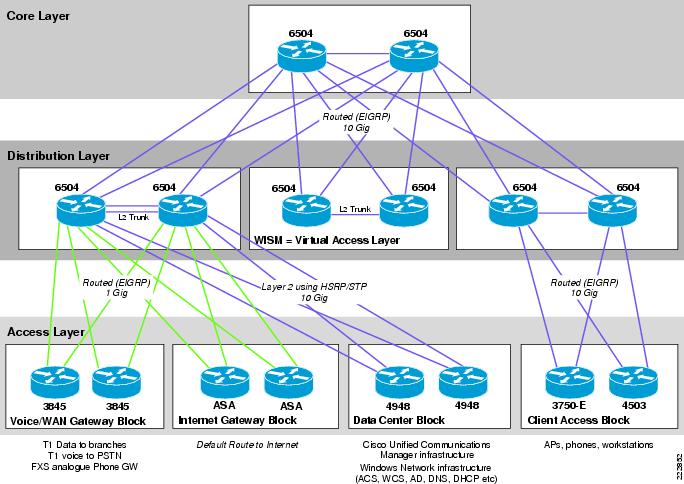
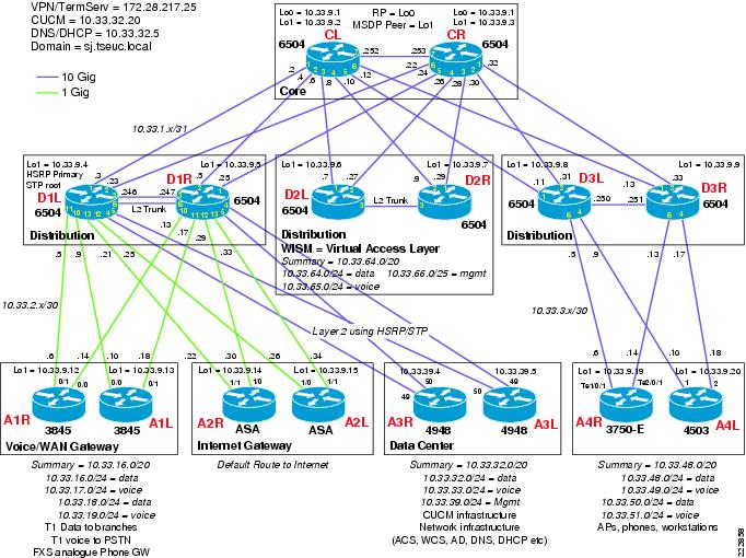
The campus design used for the VoWLAN testing is shown in Figure 6-1. Most readers will be familiar with the hierarchical, access, distribution, core design used in this network. In the past, it was common to run Layer 2 links between the access layer and the distribution layer, and to use Spanning Tree Protocol (STP) to create a redundant, loop-free topology. Current design best practice replaces this Layer 2 STP configuration with a configuration that instead routes IP packets at the access layer. Routing in the access layer allows for faster re-convergence around failure, and simplifies the network by eliminating the need for STP and Hot standby Routing Protocol (HSRP). The campus CVD design documents referenced above provide additional information and detailed test results on the advantages of a routed access layer over a Layer 2 connection.
Data center devices have some unique network connectivity requirements that make it necessary to continue to connect to the access layer using Layer 2 and not routed IP. The unique requirements of the data center network connections are described in Campus Layer 2 Spanning Tree Protocol Design for Data Center.
Figure 6-1 VoWLAN Campus Architecture
The architecture shown in Figure 6-1 differs from the existing campus CVD Routed Access Design Guide in that multiple access layer blocks are connected to a single distribution block. In a production deployment, the campus CVD Routed Access Design Guide topology should be followed. This would result in each access layer block connecting to a dedicated distribution block, where policy appropriate to that type of access layer could be applied. Following the campus CVD Routed Access Design Guide would result in the voice/WAN gateway, the Internet Gateway, and the data center access blocks all connecting to dedicated distribution blocks rather than sharing a distribution block, as is shown in Figure 6-1.
In accordance with the campus design recommendations, all router interconnections use fiber optic transport due to the superior link failure detection capabilities fiber links have when compared to wired Ethernet connections.
The Configuration section provides sample configurations that can be used as a basis for implementing the policies discussed in the following sections.
Voice and Data VLAN Separation
Separate voice and data VLANs are used for the following reasons;
•
•
•
•
Campus IP Routing Design
Most of the information in this section was taken directly from the campus CVD Routed Access Design Guide. The campus CVD Routed Access Design Guide advocates the use of Layer 3 routing to the access layer in order to obtain the highest possible network availability. Test results in the HA Campus Recovery Analysis document (available at http://www.cisco.com/en/US/netsol/ns815/networking_solutions_program_home.html) confirm the advantages of Layer 3 design over Layer 2 designs.
EIGRP Routing Protocol
The campus documents referenced above describe the use of both OSPF and EIGRP as appropriate choices for the campus routing protocol. The test results show convergence for both of these routing protocols to be essentially equivalent. For this chapter, we chose to implement EIGRP due to its superior ease of deployment.
Minimizing EIGRP Reconvergence Time
The length of time it takes for EIGRP or any routing protocol to restore traffic flows, after a network outage, within the campus is bounded by the following three main factors:
•
•
•
In the cases where the switch has redundant equal-cost paths, all three of these events are performed locally within the switch and controlled by the internal interaction of software and hardware. In the case where there is no second equal-cost path nor a feasible successor for EIGRP to use, the time required to determine the new best path is variable and primarily dependent on EIGRP query and reply propagation across the network. To minimize the time required to restore traffic in the case where a full EIGRP routing convergence is required, it is necessary to provide strict bounds on the number and range of the queries generated.
Although EIGRP provides a number of ways to control query propagation, the two main methods are route summarization and the EIGRP stub feature. In the routed access hierarchical campus design, it is necessary to use both of these mechanisms.
EIGRP Stub
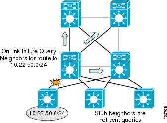
Configuring EIGRP stub on the Layer 3 access switches prevents the distribution switch from generating downstream queries.
Access Switch EIGRP Routing Process Stub Configuration
A4R-Top#sh run | beg router eigrp 100router eigrp 100passive-interface defaultno passive-interface TenGigabitEthernet1/0/1no passive-interface TenGigabitEthernet2/0/1network 10.0.0.0no auto-summaryeigrp router-id 10.33.9.19eigrp stub connectedBy configuring the EIGRP process to run in "stub connected" state, the access switch advertises all connected subnets matching the network 10.0.0.0 0.255.255.255 range. It also advertises to its neighbor routers that it is a stub or non-transit router, and thus should never be sent queries to learn of a path to any subnet other than the advertised connected routes. With the design in Figure 6-2, the impact on the distribution switch is to limit the number of queries generated to 3 or less for any link failure.
Figure 6-2 EIGRP Stub Limits the Number of Queries Generated to 3
To confirm that the distribution switch is not sending queries to the access switches, examine the EIGRP neighbor information for each access switch and look for the flag indicating queries being suppressed.
D3L#sh ip eigrp neigh det te 2/6IP-EIGRP neighbors for process 100H Address Interface Hold Uptime SRTT RTO Q Seq(sec) (ms) Cnt Num3 10.33.3.3 Te2/6 2 00:00:15 1004 5000 0 36Version 12.2/1.2, Retrans: 0, Retries: 0Stub Peer Advertising ( CONNECTED REDISTRIBUTED ) RoutesSuppressing queriesConfiguring the access switch as a stub; router enforces hierarchical traffic patterns in the network. In the campus design, the access switch is intended to forward traffic only to and from the locally connected subnets. The size of the switch and the capacity of its uplinks are specified to meet the needs of the locally-connected devices. The access switch is never intended to be a transit or intermediary device for any data flows that are not to or from locally-connected devices. The hierarchical campus is designed to aggregate the lower speed access ports into higher speed distribution uplinks, and then to aggregate that traffic up into high-speed core links. The network is designed to support redundant capacity within each of these aggregation layers of the network, but not to support the re-route of traffic through an access layer. Configuring each of the access switches as EIGRP stub routers ensures that the large aggregated volumes of traffic within the core are never forwarded through the lower bandwidth links in the access layer, and also ensures that no traffic is ever mistakenly routed through the access layer, bypassing any distribution layer policy or security controls.
Each access switch in the routed access design should be configured with the EIGRP stub feature to aid in ensuring consistent convergence of the campus by limiting the number of EIGRP queries required in the event of a route recalculation, and to enforce engineered traffic flows to prevent the network from mistakenly forwarding transit traffic through the access layer.
For more information on the EIGRP stub feature, see the following URL: http://www.cisco.com/en/US/docs/ios/12_0s/feature/guide/eigrpstb.html
Distribution Summarization
Configuring EIGRP stub on all of the access switches reduces the number of queries generated by a distribution switch in the event of a downlink failure, but it does not guarantee that the remaining queries are responded to quickly. In the event of a downlink failure, the distribution switch generates three queries; one sent to each of the core switches, and one sent to the peer distribution switch. The queries generated ask for information about the specific subnets lost when the access switch link failed. The peer distribution switch has a successor (valid route) to the subnets in question via its downlink to the access switch, and is able to return a response with the cost of reaching the destination via this path. The time to complete this event depends on the CPU load of the two distribution switches and the time required to transmit the query and the response over the connecting link. In the campus environment, the use of hardware-based CEF switching and GigE or greater links enables this query and response to be completed in less than a 100 msec.
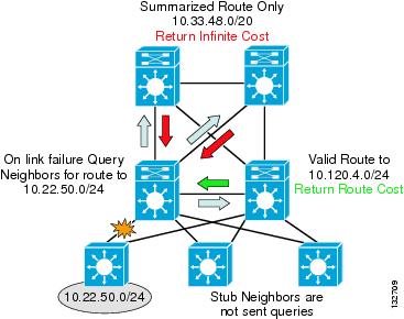
This fast response from the peer distribution switch does not ensure a fast convergence time, however, EIGRP recovery is bounded by the longest query response time. The EIGRP process has to wait for replies from all queries to ensure that it calculates the optimal loop free path. Responses to the two queries sent towards the core need to be received before EIGRP can complete the route recalculation. To ensure that the core switches generate an immediate response to the query, it is necessary to summarize the block of distribution routes into a single summary route advertised towards the core.
D3L#sh run | begin TenGigabitEthernet2/1interface TenGigabitEthernet2/1description from D3L to CLip address 10.33.1.11 255.255.255.254ip hello-interval eigrp 100 1ip hold-time eigrp 100 3ip authentication mode eigrp 100 md5ip authentication key-chain eigrp 100 eigrp-chainip pim sparse-modeip summary-address eigrp 100 10.33.48.0 255.255.240.0 5logging event link-statusload-interval 30carrier-delay msec 0mls qos trust dscpThe summary-address statement is configured on the uplinks from each distribution switch to both core nodes. In the presence of any more specific component of the 10.33.0.0/16 address space, it causes EIGRP to generate a summarized route for the 10.33.0.0/16 network, and to advertise only that route upstream to the core switches.
CL#sh ip route 10.33.50.0Routing entry for 10.33.48.0/20Known via "eigrp 100", distance 90, metric 3328, type internalRedistributing via eigrp 100Last update from 10.33.1.11 on TenGigabitEthernet2/5, 4w3d agoRouting Descriptor Blocks:* 10.33.1.13, from 10.33.1.13, 4w3d ago, via TenGigabitEthernet2/6Route metric is 3328, traffic share count is 1Total delay is 30 microseconds, minimum bandwidth is 1000000 KbitReliability 255/255, minimum MTU 1500 bytesLoading 1/255, Hops 210.33.1.11, from 10.33.1.11, 4w3d ago, via TenGigabitEthernet2/5Route metric is 3328, traffic share count is 1Total delay is 30 microseconds, minimum bandwidth is 1000000 KbitReliability 255/255, minimum MTU 1500 bytesLoading 1/255, Hops 2With the upstream route summarization in place, whenever the distribution switch generates a query for a component subnet of the summarized route, the core switches reply that they do not have a valid path (cost = infinity) to the subnet query. The core switches are able to respond within less than 100 msec if they do not have to query other routers before replying back to the subnet in question.
Figure 6-3 shows an example of summarization toward the core.
Figure 6-3 Summarization toward the Core Bounds EIGRP Queries for Distribution Block Routes
Using a combination of stub routing and summarizing the distribution block routes upstream to the core both limits the number of queries generated and bounds those that are generated to a single hop in all directions. Keeping the query period bounded to less than 100 msec keeps the network convergence similarly bounded under 200 msec for access uplink failures. Access downlink failures are the worst case scenario because there are equal-cost paths for other distribution or core failures that provide immediate convergence.
Route Filters
The discussion on EIGRP stub above noted that in the structured campus model, the flow of traffic follows the hierarchical design. Traffic flows pass from access through the distribution to the core and should never pass through the access layer unless they are destined to a locally attached device. Configuring EIGRP stub on all the access switches aids in enforcing this desired traffic pattern by preventing the access switch from advertising transit routes. As a complement to the use of EIGRP stub, Cisco recommends applying a distribute-list to all the distribution downlinks to filter the routes received by the access switches. The combination of "stub routing" and route filtering ensures that the routing protocol behavior and routing table contents of the access switches are consistent with their role, which is to forward traffic to and from the locally connected subnets only.
Cisco recommends that a default route (0.0.0.0 mask 0.0.0.0) be the only route advertised to the access switches.
D3L#sh run | begin router eigrp 100router eigrp 100...network 10.0.0.0distribute-list only-default out TenGigabitEthernet2/4distribute-list only-default out TenGigabitEthernet2/6...eigrp router-id 10.33.9.8!...!ip access-list standard only-defaultpermit 0.0.0.0remark redistribute default route to access layer stub-routersNo mask is required in the configuration of this access list because the assumed mask, 0.0.0.0, permits only the default route in the routing updates.
In addition to enforcing consistency with the desire for hierarchical traffic flows, the use of route filters also provides for easier operational management. With the route filters in place, the routing table for the access switch contains only the essential forwarding information. Reviewing the status and/or troubleshooting the campus network is much simpler when the routing tables contain only essential information.
A4L#sh ip routeCodes: C - connected, S - static, R - RIP, M - mobile, B - BGPD - EIGRP, EX - EIGRP external, O - OSPF, IA - OSPF inter areaN1 - OSPF NSSA external type 1, N2 - OSPF NSSA external type 2E1 - OSPF external type 1, E2 - OSPF external type 2i - IS-IS, su - IS-IS summary, L1 - IS-IS level-1, L2 - IS-IS level-2ia - IS-IS inter area, * - candidate default, U - per-user static routeo - ODR, P - periodic downloaded static routeGateway of last resort is 10.33.3.24 to network 0.0.0.02.0.0.0/32 is subnetted, 1 subnetsC 2.2.2.2 is directly connected, Loopback210.0.0.0/8 is variably subnetted, 5 subnets, 3 masksC 10.33.49.0/24 is directly connected, Vlan49C 10.33.48.0/24 is directly connected, Vlan48C 10.33.3.4/31 is directly connected, TenGigabitEthernet1/1C 10.33.3.24/31 is directly connected, TenGigabitEthernet1/2C 10.33.9.20/32 is directly connected, Loopback1D*EX 0.0.0.0/0 [170/3584] via 10.33.3.24, 3w4d, TenGigabitEthernet1/2[170/3584] via 10.33.3.4, 3w4d, TenGigabitEthernet1/1If the network does not contain a default route, it may be acceptable to use an appropriate full network summary route in its place; that is, 10.0.0.0/8, or a small subset of summary routes that summarize all possible destination addresses within the network.
CEF Switching
Per-destination load balancing is enabled by default when you enable CEF, and is the load balancing method of choice for most situations. Per-destination load balancing allows the router to use multiple paths to achieve load sharing. Packets for a given source-destination host pair are guaranteed to take the same path, even if multiple paths are available.
When you enable CEF or dCEF globally, all interfaces that support CEF are enabled by default.
Adjusting EIGRP timers
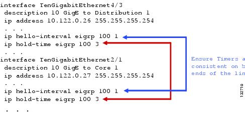
The recommended best practice for campus design is to use point-to-point fiber connections for all links between switches. Link failure detection via 802.3z and 802.3ae remote fault detection mechanism provide for recovery from most campus switch component failures. Cisco recommends in the Layer 3 campus design that the EIGRP hello and dead timers be reduced to 1 and 3 seconds, respectively (see Figure 6-4). The loss of hellos and the expiration of the dead timer provides a backup to the L1/2 remote fault detection mechanisms. Reducing the EIGRP hello and hold timers from defaults of 5 and 15 seconds provides for a faster routing convergence in the rare event that L1/2 remote fault detection fails to operate, and hold timer expiration is required to trigger a network convergence because of a neighbor failure.
Figure 6-4 Reducing EIGRP Hello and Dead Timers
Campus Layer 2 Spanning Tree Protocol Design for Data Center
Much of the information in this section is summarized from the Data Center Infrastructure 2.5 Design Guide. For details, refer to this guide at: http://www.cisco.com/en/US/docs/solutions/Enterprise/Data_Center/DC_Infra2_5/DCI_SRND_2_5_book.html.
Data Center Layer Introduction
In the test network used for this document, the data center is used to connect network infrastructure devices such as Cisco Unified Communications Manager, Cisco Unified Unity, ACS, WCS, DNS, DHCP.
While the rest of the campus network uses Layer 3 routing (EIGRP) all the way to the access layer, the unique requirements of data center deployments require a Layer 2 connection to the data center. A Layer 2 access topology provides the following unique capabilities required in the data center:
•
•
•
•
Spanning Tree Triangle Looped Topology
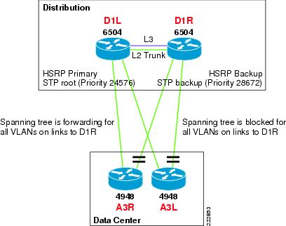
The triangle looped topology utilized in the network used for this document is currently the most widely implemented in the enterprise data center. This topology provides a deterministic design that makes it easy to troubleshoot while providing a high level of flexibility (see Figure 6-5).
Figure 6-5 Triangle Looped Access Topology
In a triangle looped access layer design, it is desirable to align the spanning tree root, HSRP default gateway, and active service modules on the same aggregation switch, as shown in Figure 6-5. Aligning the access layer switch uplink that is in the forwarding state directly to the same switch that is the primary default gateway and active service module/appliance optimizes the traffic flows. Otherwise, traffic flows can hop back and forth between aggregation switches, creating undesirable conditions and difficulty in troubleshooting.
Lab Implementation Deviations from Standard Design Principals in the Data Center
In the network used for this chapter, multiple access layer blocks are connected to a single distribution block. This was done to reduce the number of distribution layer switches required. In a production deployment, the data center access-block would connect to a dedicated distribution block. In a production network, the distribution block dedicated to the data center access-block would run a variety of service modules supporting data center access. Example service modules include:
•
•
•
•
•
•
While some combination of these would be expected in a production distribution layer block, our test network is not specifically focused on data center testing, and we have implement the network without any of these service modules.
Campus Quality of Service (QoS)
Much of the information in this section is summarized from the Enterprise QoS Solution Reference Network Design Guide Version 3.3. For details refer to this guide at: http://www.cisco.com/en/US/docs/solutions/Enterprise/WAN_and_MAN/QoS_SRND/QoS-SRND-Book.html.
QoS refers to the set of tools and techniques used to manage network resources. QoS technologies allow different types of traffic to contend inequitably for network resources. Using QoS, some network traffic such as Voice, video, or critical data may be granted priority or preferential services from network devices; this prevents lower priority background traffic from degrading the quality of these strategic applications.
Until recently, QoS was not a great concern in the enterprise campus due to the large amount of available bandwidth as well as the asynchronous nature of data traffic and the ability of applications to tolerate the effects of buffer overflows and packet loss. However, with new applications such as voice and video, which are sensitive to packet loss and delay it is important to utilize quality of service features to protect high priority traffic.
Campus QoS Services Required
Access switches require the following QoS policies:
•
•
•
Distribution and core switches require the following QoS policies:
•
•
•
These recommendations are summarized in Figure 6-6.
Figure 6-6 Typical Campus Oversubscription Ratios
Campus QoS and Interface Queuing
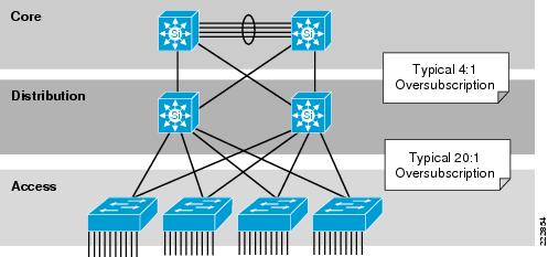
Many campus links are underutilized. Some studies have shown that 95 percent of campus access layer links are used at less than 5 percent of their capacity. This means that you can design campus networks to accommodate oversubscription between access, distribution and core layers. Oversubscription allows for uplinks to be used more efficiently and more importantly, reduces the overall cost of building the campus network.
Common campus oversubscription values are 20:1 for the access-to-distribution layers and 4:1 for the distribution-to-core layers, as shown in Figure 6-7.
Figure 6-7 QoS Requirement within the Campus
The potential for congestion exists in campus uplinks because of oversubscription ratios and speed mismatches in campus downlinks (for example, GigabitEthernet to FastEthernet links). The only way to provision service guarantees in these cases is to enable advanced interface queuing at these points.
For a given input or output interface, Cisco IOS can manage multiple queues. Traffic of a particular priority is mapped into the appropriate queue for that traffic class. Cisco IOS queue scheduling algorithms can then be configured to service those queues, giving more priority to servicing the queues containing higher priority traffic. In this way, higher priority traffic is protected from queue overruns caused by lower priority traffic.
QoS and Wired IP Phones
This section is specific to wired Ethernet-attached IP phone. Wireless LAN IP phones such as the Cisco 7921G use a different QoS procedure and are discussed in Chapter 10, "Cisco Unified IP Phone 7921 Implementation for Voice over WLAN."
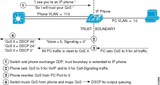
Cisco wired IP phones perform an intelligent exchange of information between the phone and the switchport it is plugged into using Cisco Discovery Protocol (CDP). When the switch discovers a Cisco IP phone, it can extend QoS trust to it dynamically.
Figure 6-8 shows a conditional trust boundary extension granted to an IP phone that has passed a CDP exchange.
Figure 6-8 Conditionally Trusted Endpoint Trust Boundary Extension and Operation
The sequence shown in Figure 6-8 is the following:
Step 1
Step 2
Step 3
Step 4
AutoQoS and VoIP
When the main business objective of the QoS deployment is to enable QoS for IP Telephony only (i.e., without Scavenger-class QoS), then the network administrator may choose to take advantage of the Cisco AutoQoS VoIP feature.
AutoQoS VoIP is essentially an intelligent macro that enables an administrator to enter one or two simple AutoQoS commands to enable all the appropriate features for the recommended QoS settings for VoIP and IP telephony for a specific platform and/or a specific interface.
AutoQoS VoIP automatically configures the best-practice QoS configurations (based on previous Cisco Enterprise QoS SRNDs) for VoIP on Cisco Catalyst switches and IOS routers. By entering one global and/or one interface command (depending on the platform), the AutoQoS VoIP macro then would expand these commands into the recommended VoIP QoS configurations (complete with all the calculated parameters and settings) for the platform and interface on which the AutoQoS VoIP macro is applied.
For example, on Cisco Catalyst switches, AutoQoS performs the following automatically:
•
•
•
•
•
•
QoS Policing
At the time of writing, classification using a port trust state (for example, mls qos trust [cos | dscp | ip-precedence] and a policy map (for example, service-policy input policy-map-name) are mutually exclusive on the Catalyst 2970/3560/3750. The last one configured overwrites the previous configuration. This limitation is to be addressed; consult the latest Catalyst 2970/3560/3750 QoS documentation for updates on this limitation.
Because of the above limitation, policing will not be discussed in the configuration section of this document. For detailed guidance on policing configuration, refer to the Enterprise QoS Solution Reference Network Design Guide Version 3.3 at the following URL: http://www.cisco.com/en/US/docs/solutions/Enterprise/WAN_and_MAN/QoS_SRND/QoS-SRND-Book.html
Campus Multicast
For complete details on the recommended campus multicast design, see the Cisco AVVID Network Infrastructure IP Multicast Design SRND at the following URL: http://www.cisco.com/application/pdf/en/us/guest/tech/tk363/c1501/ccmigration_09186a008015e7cc.pdf.
When designing multicast networking, a routed access design has advantages over a design that has Layer 2 to the distribution layer. In the Layer 2 design, there are two routers on the same subnet as the multicast hosts. This results in the following;
•
•
•
For each specific VLAN The root bridge, the HSRP active node, and the PIM DR should all be on the same distribution switch.
In the routed access design, this need for synchronized configuration is removed because there is only one router on the local segment, which by default results in synchronization of the unicast and multicast traffic flows. Additionally, with the migration of the multicast router from the distribution to the access, there is no longer a need to tune the PIM hello timers to ensure rapid convergence between the distribution nodes in the case of a failure. The same remote fault indicator mechanisms that trigger rapid unicast convergence drive the multicast software and hardware recovery processes, and there is no need for Layer 3 detection of path or neighbor failure across the Layer 2 access switch. The presence of a single router for each access VLAN also removes the need to consider non-reverse path forwarding (non-RPF) traffic received on the access side of the distribution switches. A multicast router drops any multicast traffic received on a non-RPF interface. If there are two routers for a subnet, the DR forwards the traffic to the subnet, and the non-DR receives that traffic on its own VLAN interface where it fails the RPF check and so must be dropped
Multicast Traffic Flows and Router Functions
In the Layer 3 access design, there is a single router on the access subnet and no non-RPF traffic flows. Although the current generation of Cisco Catalyst switches can process and discard all non-RPF traffic in hardware with no performance impact or access list configuration required, the absence of non-RPF traffic simplifies operation and management.
The following summarizes the campus multicast configuration implementation:
•
•
•
•
•
•
•
Campus Security
The Campus Security section is focused on the Catalyst Integrated Security Features (CISF) features found in the access layer switches connecting end-user devices to the network.
Much of the information in this section is summarized from Cisco Unified Communications SRND Based on Cisco Unified Communications Manager 6.x at the following URL: http://www.cisco.com/en/US/docs/voice_ip_comm/cucm/srnd/6x/uc6_0.html
Refer to the above document as well as the relevant access-layer switch documentation for more details.
Catalyst Integrated Security Features (CISF)
Layer 2 switched environments can prove easy targets for security attacks. These attacks exploit normal protocol processing such as a switches' ability to learn MAC addresses, end-station Media Access Control (MAC) address resolution through Address Resolution Protocol (ARP) or Dynamic Host Configuration Protocol (DHCP) IP address assignments.
The rich set of integrated security features on Cisco Catalyst Switches (CISF) protect your critical network infrastructure with easy-to-use tools that effectively prevent the most common—and potentially damaging— Layer 2 security threats.
Port Security
Function
Shuts down MAC address-flooding attacks .
How It Works
A classic attack on a switched network is a MAC content-addressable memory (CAM) flooding attack. This type of attack floods the switch with so many MAC addresses that the switch does not know which port an end station or device is attached to. When the switch does not know which port a device is attached to, it broadcasts the traffic destined for that device to the entire VLAN. In this way, the attacker is able to see all traffic that is coming to all the users in a VLAN.
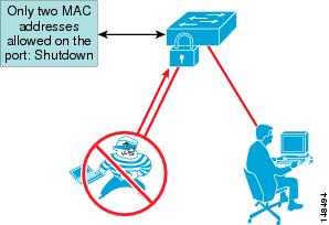
Port security limits the number of MAC addresses allowed to access individual switch ports thus protecting against MAC flooding attacks from hacker tools such as macof (see Figure 6-9).
Figure 6-9 Limited Number of MAC Addresses Prevents Rogue Network Extensions
DHCP Snooping
Function
Prevent rogue DHCP server attacks, DHCP starvation attacks, create client binding information used by additional CISF tools
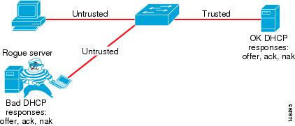
Figure 6-10 Using DHCP Snooping
DHCP Snooping: Prevent Rogue DHCP Server Attacks
How It Works
Dynamic Host Configuration Protocol (DHCP) Snooping prevents a non-approved DHCP or rouge DHCP server from handing out IP addresses on a network by blocking all replies to a DHCP request unless that port is allowed to reply. When enabled, DHCP Snooping treats all ports in a VLAN as untrusted by default. An untrusted port is a user-facing port that should never make any reserved DHCP responses. If an untrusted DHCP-snooping port makes a DHCP server response, it will be blocked from responding. Therefore, rogue DHCP servers will be prevented from responding. However, legitimately attached DHCP servers or uplinks to legitimate servers must be trusted.
DHCP Snooping: Prevent DHCP Starvation Attacks
How It Works
DHCP address scope starvation attacks from tools such as Gobbler are used to create a DHCP denial-of-service (DoS) attack. Because the Gobbler tool makes DHCP requests from different random source MAC addresses, you can prevent it from starving a DHCP address space by using port security to limit the number of MAC addresses. However, a more sophisticated DHCP starvation tool can make the DHCP requests from a single source MAC address and vary the DHCP payload information. With DHCP Snooping enabled, untrusted ports will make a comparison of the source MAC address to the DHCP payload information and fail the request if they do not match
DHCP Snooping: Binding Information
How It Works
Another function of DHCP Snooping is to record the DHCP binding information for untrusted ports that successfully get IP addresses from the DHCP servers. The binding information is recorded in a table on the Cisco Catalyst switch. The DHCP binding table contains the IP address, MAC address, lease length, port, and VLAN information for each binding entry. The binding information from DHCP Snooping remains in effect for the length of the DHCP binding period set by the DHCP server (that is, the DHCP lease time). The DHCP binding information is used to create dynamic entries for Dynamic ARP Inspection (DAI) to limit ARP responses for only those addresses that are DHCP-bound. The DHCP binding information is also used by the IP source guard to limit sourcing of IP packets to only those addresses that are DHCP-bound.
Dynamic ARP Inspection
Function
Adds security to ARP using DHCP snooping table.
How It Works
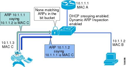
Dynamic Address Resolution Protocol (ARP) Inspection (DAI) is a feature used on the switch to prevent Gratuitous ARP attacks on the devices plugged into the switch and on the router.
Gratuitous ARP can be exploited by malicious programs that want to illegitimately take on the identity of another station. When a malicious station redirects traffic to itself from two other stations that were talking to each other, the hacker who sent the GARP messages becomes the man-in-the-middle. Hacker programs such as ettercap do this with precision by issuing "private" GARP messages to specific MAC addresses rather than broadcasting them. In this way, the victim of the attack does not see the GARP packet for its own address. Ettercap also keeps its ARP poisoning in effect by repeatedly sending the private GARP messages every 30 seconds.
Dynamic ARP Inspection (DAI) is used to inspect all ARP requests and replies (gratuitous or non-gratuitous) coming from untrusted (or user-facing) ports to ensure that they belong to the ARP owner. The ARP owner is the port that has a DHCP binding which matches the IP address contained in the ARP reply. ARP packets from a DAI trusted port are not inspected and are bridged to their respective VLANs.
Figure 6-11 Using DHCP Snooping and DAI to Block ARP Attacks:
IP Source Guard
Function
Prevents IP host spoofing.
How It Works
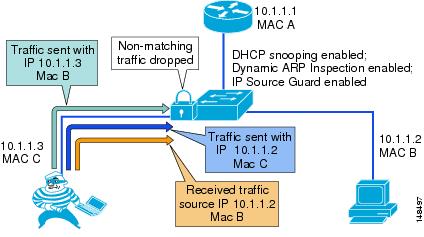
IP address spoofing is commonly used to perform DoS attacks on a second party. A simple example of this occurs when an attacker pings a third-party system while sourcing the IP address of the second party that is being attacked (see Figure 6-12). The ping response will be directed to the second party from the third-party system. Aggressive SYN-flooding originating from spoofed IP addresses is another common type of attack used to overwhelm a server with TCP half-sessions.
The IP Source Guard (IPSG) feature, when invoked, dynamically creates an ACL based on the contents of the DHCP Snooping binding table. This ACL ensures that traffic is sourced from the IP address issued at DHCP binding time and prevents any traffic from being forwarded by other spoofed addresses. While DHCP Snooping is a prerequisite for IP Source Guard, DAI is not. However, Cisco recommend that you enable DAI in addition to IP Source Guard to prevent ARP-poisoning man-in-the-middle attacks in addition to IP address spoofing.
Figure 6-12 Using IP Source Guard to Prevent Address Spoofing:
Network Time Services
An essential element of network management, troubleshooting, and security operations is to have all network elements (including routers switches and servers) synchronized to a common clock source.
Network Time Protocol (NTP) is most commonly used to synchronize clocks in network equipment. NTP provides accuracies typically within a millisecond on LANs and up to a few tens of milliseconds on WANs.
By synchronizing the clocks across the network it is possible to examine the exact sequence in which events occurred. This ability to analyze and correlate the sequence of events across multiple network elements makes it much easier to determine the root cause of network problems or security issues.
The configuration section of this document shows the commands used in our network to have NTP synchronize to an external time source. In most production the external time source used would be redundant, dedicated hardware that synchronizes via a GPS receiver to a clock source that is itself directly synchronized to an atomic clock.
NTP links
•
•
•
•
•
UniDirectional Link Detection (UDLD)
Use UDLD to protect against one-way up/up connections. In fiber topologies where fiber optic interconnections are used, which is common in a campus environment, physical misconnections can occur that allow a link to appear to be up/up when there is a mismatched set of transmit/receive pairs. When such a physical misconfiguration occurs, protocols such as EIGRP or STP can cause network instability. UDLD detects these physical misconfigurations and disables the ports in question
Configuration
Software versions used in test network
Lab Network used for Configuration Examples
Throughout the configuration section of this chapter, many configuration examples are shown from actual routers and switches used in the lab build-out used to test and write this document. Figure 6-13 provides a detailed view of the lab network, that will assist in understanding the configuration examples below.
Figure 6-13 TSE VoWLAN campus Architecture Detailed
Campus EIGRP Routing Configuration
Campus EIGRP Routing Configuration Common to all Routers
Table 6-2 shows the configuration commands that are common to all routers/switches in the example network. The IP addressing is based on the network diagram shown in Figure 6-1.
Note
EIGRP Configuration Specific to Core Routers
There is no special routing policy applied to the core routers; their configuration is left as simple as possible so as to not interfere with their primary function of routing packets.
EIGRP Configuration Specific to Distribution Routers
EIGRP Configuration Specific to Access Routers
Campus Layer 2 Spanning Tree Protocol Design for Data Center Configuration
Campus QoS Configuration
The auto qos voip commands shown below are macros. They generate many configuration statements that configure CoS-to-DSCP mappings, interface queue discard thresholds, the mapping of specific CoS and DSCP values to a particular queue and threshold, and queue buffer sizes as well as generating the specific interface QoS trust policies. The commands generated can be observed by entering the debug auto qos command before beginning the configuration.
Campus Routed Multicast configuration
This section provides the configuration required for the campus network with the exception of the connection to the datacenter where slightly different configuration is required for the Layer 2 connections from the distribution to the access layers.
Campus Multicast Configuration Common to all Multicast-enabled Routers
The voice/WAN Gateway routers and the Internet Gateway routers are not multicast enabled.
Campus Multicast Configuration for Core Routers
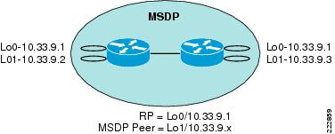
Figure 6-14 provides a logical view of the MSDP configuration of the core switches.
Figure 6-14 Logical View of MSDP Configuration
Campus Multicast Configuration for Distribution Routers
No multicast-specific configuration is required on distribution routers.
Campus Multicast Configuration for Access Routers
Campus Multicast Configuration for Layer 2 Switches used for Data Center
This section provides the configuration required for the datacenter where slightly different configuration is required for the Layer 2 connections from the distribution to the access layers.
Campus Multicast configuration for Layer 2 Distribution-Layer switches used for Datacenter
Campus Multicast Configuration for Layer 2 ACcess-Layer Switches used for Data Center
No multicast-specific configuration is required on L2 access layer switches.
Campus Multicast Configuration for Layer 2 Switches used for Data Center Verification
Access Switch Catalyst Integrated Security Features (CISF) Configuration
The configuration below is applied to all access layer switches that will have end-users or APs connected to them. The port security configuration permits a maximum of 2 MAC addresses; this is enough for a Cisco IP phone with an attached PC to be connected. An LWAPP AP tunnels all client traffic to the LWAPP controller, so the switch it is connected to will only ever see the MAC and IP address of the AP on that port.
Router Time Services Configuration
Uni-Directional Link Detection (UDLD) Configuration
Table 6-16 UniDirectional Link Detection (UDLD) Configuration
UDLD is not supported on the ASAs or 3800s used in this document, and is enabled by default on the 4948s.