-
Medium Enterprise Design Profile Reference Guide
-
Medium Enterprise Design Profile(MEDP)—Service Fabric Design Considerations
-
Medium Enterprise Design Profile (MEDP)—LAN Design
-
Medium Enterprise Design Profile (MEDP)—WAN Design
-
Medium Enterprise Design Profile (MEDP)—Mobility Design
-
Medium Enterprise Design Profile (MEDP)—Network Security Design
-
Reference Documents
-
Table Of Contents
Medium Enterprise Design Profile (MEDP)—WAN Design
WAN Aggregation Platform Selection in the Medium Enterprise Design Profile
Main Site WAN Aggregation Platform Selection
Large Remote Site WAN Aggregation Platform Selection
Medium Remote Site WAN Aggregation Platform Selection
Small Remote Site WAN Aggregation Platform Selection
Implementation of WAN Reference Design
QoS Implementation at WAN Aggregation Router 1
Implementation Steps for QoS Policy at WAN Aggregation Router 1
QoS Policy Implementation for WAN Aggregation Router 2
QoS Policy Between the Main Site and Large Remote Site
QoS Policy Between the Main Site and Medium Remote Site Location
QoS Policy Between Main Site and Small Remote Site Location
QoS Policy Implementation Between the Main Site and Core
QoS Policy Between Large Remote Site and Main Site Location
QoS Policy Between Remote Medium Site and Main Site Location
QoS Policy Implementation Between Small Remote Site and Main Site Location
Medium Enterprise Design Profile (MEDP)—WAN Design
WAN Design
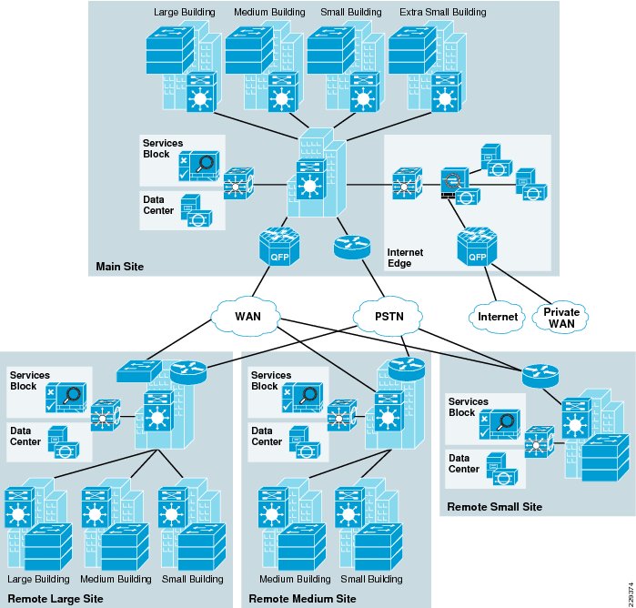
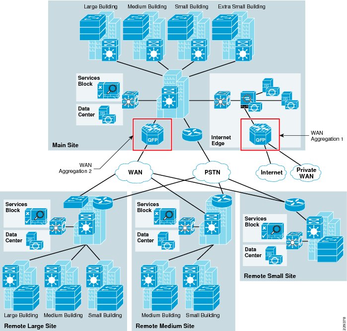
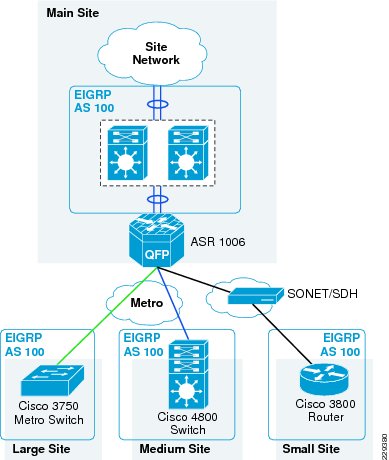
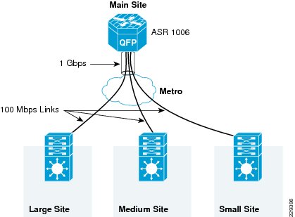
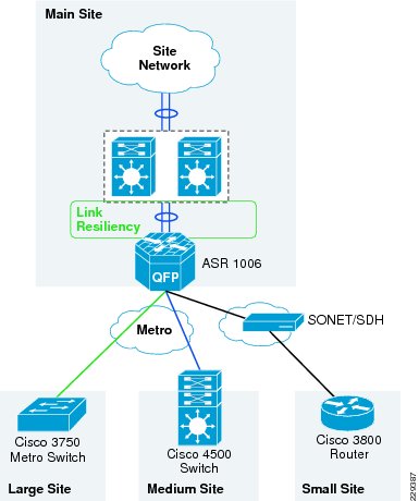
The Medium Enterprise WAN Design Profile is a multi-site design where a site consists of multiple buildings and services. The sites are interconnected through various WAN transports as shown in Figure 3-1.
Figure 3-1 Medium Enterprise WAN Design Diagram
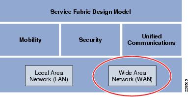
Within the Medium Enterprise Design Profile, the service fabric network provides the foundation on which all the solutions and services are built upon to solve the business challenges. This service fabric consists of four distinct components as shown in Figure 3-2.
Figure 3-2 The Service Fabric Design Model
This chapter discusses the WAN design component of the Medium Enterprise Design Profile. This section discusses how the WAN design is planned for medium enterprises, the assumptions made, the platforms chosen, and the justification for choosing a platform. The WAN design is highly critical to provide network access for remote sites to the main site, as well as connectivity to other networks, and general Internet access for the entire enterprise. The WAN design should not be viewed merely for providing access, but mainly to see how the business requirements can be met. Therefore, it is important for communication to exist between the employees, customers, and partners. This communication could be with voice, video, or data applications. Moreover, the video applications, may possess, flavors ranging from desktop video to real-time video. To provide this collaborative environment, highly resilient and, highly performing WAN designs are required.
The main components of Medium Enterprise Design Profile for WAN architecture are as follows:
•
WAN transport
•
•
WAN Transport
This section discusses the different WAN transports present in the Medium Enterprise Design Profile.
Private WAN Service
The Medium Enterprise Design Profile consists of several locations. These locations have similar architecture as the main site. However, these sites need to collaborate with each other to meet the business objectives. Therefore, a WAN network that can support the following requirements is needed:
•
•
•
•
•
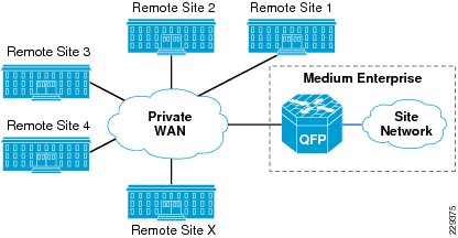
To support these requirements enterprises need to have a private WAN service to provide connectivity between remote sites, and main site. See Figure 3-3.
Figure 3-3 Medium Enterprise Connectivity to Other Remote Sites Using Private WAN
Internet Service
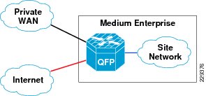
The physical connection for reaching the Internet and the private WAN network is same; however, both circuits are logically separated using different subinterfaces. Therefore, it is similar to a situation where a customer is connected to different service providers. See Figure 3-4.
Figure 3-4 Medium Enterprise Internet Service
Metro Service
Metro Ethernet is one of the fastest growing WAN transport technologies in the telecommunications industry. The advantages of using this WAN transport are as follows:
•
–
–
•
–
–
–
•
–
•
–
–
There are two popular methods of service for Metro Ethernet:
1.
2.
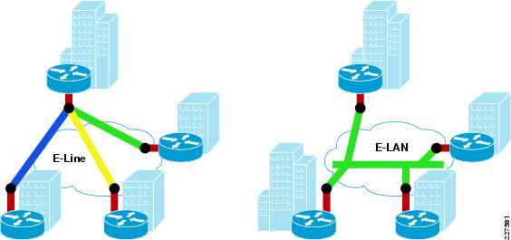
EVPL, like Frame Relay, provides for multiplexing multiple point-to-point connections over a single physical link. In the case of Frame Relay, the access link is a serial interface to a Frame Relay switch with individual data-link connection identifiers (DLCIs), identifying the multiple virtual circuits or connections. In the case of EVPL, the physical link is Ethernet, typically FastEthernet or Gigabit Ethernet, and the multiple circuits are identified as VLANs by way of an 802.1q trunk.
E-LAN, also known as Virtual Private LAN Services (VPLS), provides any-to-any connectivity within the Metro area, which allows flexibility. It passes 802.q trunks across the SP network known as Q-in-Q.
Figure 3-5 shows the difference between these services.
Figure 3-5 Different Services Available
This section discusses how the Metro service is designed in the Medium Enterprise Design Profile. The Metro service is used to provide connectivity between the remote sites to the main site. The key reasons for recommending Metro service for Medium Enterprise are as follows:
•
•
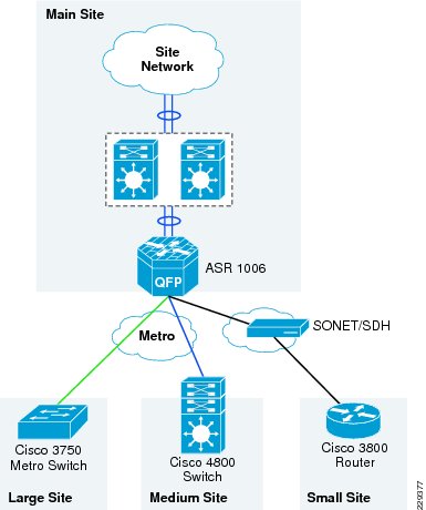
Therefore, in this design, it is recommended that the remote large and medium remote site locations use E-line service to connect to the main site. Figure 3-6 shows how the remote site locations are connected to main site using Metro service.
Figure 3-6 The Metro Transport Deployment in Medium Enterprise WAN Design
Leased-Line Service
The WAN bandwidth requirement for a small remote site is assumed to be 20Mbps. Cisco recommends that the small remote site connect to the main site using a private leased-line service. The leased-line service is more readily available for these type of locations and the bandwidth is sufficient for the small remote site application requirements.
WAN Aggregation Platform Selection in the Medium Enterprise Design Profile
In addition to selecting the WAN service for connectivity between remote site locations and access to the Internet, choosing the appropriate WAN aggregation router is essential. For each location in the Medium Enterprise Design Profile various WAN aggregation platforms are selected based on the requirements.
Main Site WAN Aggregation Platform Selection
A WAN aggregation router aggregates all the incoming WAN circuits from various locations in the network as well as the Internet and also provides the proper QoS required for application delivery. Cisco recommends the Cisco ASR family of routers as the WAN aggregation platform for the main site location.
The Cisco ASR 1000 Series Router family consists of three different models:
•
•
•
In Medium Enterprise Design Profile, there are two places where the WAN aggregation occurs in the main site location. The first place is where the main site location connects to outside world using private WAN and Internet networks. The second place is where all the remote sites connect to the main site. Figure 3-7 shows the two different WAN aggregation devices.
Figure 3-7 The WAN Aggregation Points in Medium Enterprise WAN Design
WAN Aggregation 1
A Cisco ASR 1004 Series router is recommended as the WAN aggregation platform for private WAN/Internet connectivity. This choice was made considering the cost and required features—performance, QoS, routing, and resiliency—that are essential requirements for WAN aggregation router. Moreover, this platform contains built-in resiliency capabilities such as ISSU and IOS-based redundancy.
WAN Aggregation 2
The second WAN aggregation device provides connectivity to the large and medium remote sites to the main site. To perform this aggregation, the Cisco ASR 1006 router with redundant route processors and redundant ESP's has been recommended for the following reasons:
•
•
•
Large Remote Site WAN Aggregation Platform Selection
The WAN connectivity between the large remote site to the main site is fairly simpler because of the lack of requirements of advanced encryption technologies. Therefore, the main purpose is to reduce the cost and try to consolidate the WAN functionality into the distribution device at the large site. However, at the large remote site, as per the site LAN design document, VSS has been chosen as technology on the distribution switch, and VSS does not support WAN functionality. Therefore, a dedicated WAN aggregation device is needed to perform that functionality, which can be an ASR, 7200, or 3750ME switches. Out of these choices, considering the cost/performance criteria, the Cisco 3750ME switch was selected to perform the WAN aggregation. The Cisco 3750 Metro switch has the following features/capabilities to adequately meet the requirements:
•
•
•
•
Medium Remote Site WAN Aggregation Platform Selection
As discussed in Chapter 2, "Medium Enterprise Design Profile (MEDP)—LAN Design," the medium remote site collapses the WAN edge and core-layer LAN functionality into a single switch to provide cost effectiveness to meet the budget needs for this size location. The remote medium site is connected to the main site location through Metro service. At the remote medium site, the WAN and LAN aggregation platform is the Cisco Catalyst 4507 switch. This switch has the necessary features to perform as WAN router. However, if there is the need for advanced WAN features such as MPLS, the Cisco Catalyst 3750 ME, Cisco ISR Series router or upgrading to the Cisco Catalyst 6500 series could be explored as an option. For this design, the Cisco Catalyst 4500 Series switches has been chosen to perform the dual functionality as WAN router, in addition to its role as core-layer LAN switch.
Small Remote Site WAN Aggregation Platform Selection
The small remote site is connected to main site using a private leased-line service. The WAN speed between the small remote site and the main site location is assumed to be around 20Mbps, and this service is provided by a traditional leased line. Since it is a leased-line circuit, WAN devices such as Cisco 3750 Metro or 4507 switch cannot be used. Therefore, an integrated services router is needed to meet the requirement. For this reason, the Cisco 3845 Series router is chosen as the WAN platform for the small remote site. The main advantages of using the Cisco 3845 Series router are as follows:
•
•
•
•
•
Implementation of WAN Reference Design
The following section discusses the implementation details for the Medium Enterprise Design Profile. The major components of the implementation are the following:
•
•
•
•
•
WAN Infrastructure Design
As explained in the design considerations (where??? in chapter 1??), the Medium Enterprise Design Profile uses two different services to connect the remote site locations to the main site location. The large remote site and medium remote site would connect to main site using Metro Ethernet services. The small remote site uses a leased-line service to connect to the main site location. The large remote site, due to its size, is recommended to have 1Gbps Metro service to the main site where as the small remote site location is recommended to have at least 20Mbps of bandwidth to main site. The following section provides the configuration details of all the WAN devices needed to establish the WAN connectivity.
Configuration of WAN Interfaces at WAN Aggregation Router 2
The following is configuration of WAN interfaces on WAN aggregation router 2, which aggregates all the connections from the remote site locations to the main site:
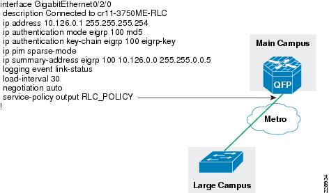
interface GigabitEthernet0/2/0description Connected to cr11-3750ME-RLCip address 10.126.0.1 255.255.255.254!interface GigabitEthernet0/2/1description Connected to cr11-4507-RMCdampeningno ip addressload-interval 30carrier-delay msec 0negotiation autocdp enableservice-policy output PARENT_POLICYhold-queue 2000 inhold-queue 2000 out!interface GigabitEthernet0/2/1.102encapsulation dot1Q 102ip address 10.126.0.3 255.255.255.254!!Configuration of WAN Interface at 3750 Large Remote Site
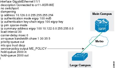
The following is configuration of WAN interface at the 3750 large remote site switch, which is connected to main site:
interface GigabitEthernet1/1/1description Connected to cr11-ASR-WEno switchportdampeningip address 10.126.0.0 255.255.255.254Configuration of WAN interface at 4500 Medium Remote Site
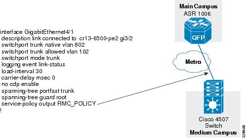
The following is the configuration of WAN interface at the medium remote site connected to the main site:
interface GigabitEthernet4/1description link connected to cr13-6500-pe2 gi3/2switchport trunk native vlan 802switchport trunk allowed vlan 102switchport mode trunklogging event link-statusload-interval 30carrier-delay msec 0no cdp enablespanning-tree portfast trunkspanning-tree guard root!interface Vlan102description Connected to cr11-ASR-WEdampeningip address 10.126.0.2 255.255.255.254load-interval 30carrier-delay msec 0Leased-Line Service
The WAN bandwidth requirement for a small remote site is assumed to be 20Mbps. Cisco recommends that the small remote site connect to the main site using a private leased-line service. The leased-line service is more readily available for these type of locations and the bandwidth is sufficient for the small remote site application requirements. To implement this design, a serial SPA is needed on the ASR 1006 WAN aggregation router at the main site and this SPA needs to be enabled for T3 interface type. The configuration below illustrates how to enable and configure the T3 interface.
The following configuration steps are needed to build the lease-line service between the main site and small remote site:
Step 1
card type t3 0 3Step 2
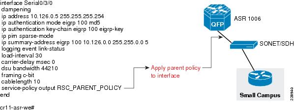
interface Serial0/3/0dampeningip address 10.126.0.5 255.255.255.254Configuration of WAN Interface at Small Remote Site Location
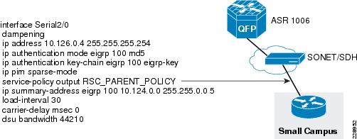
The following is configuration of WAN interface at the small remote site location:
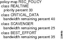
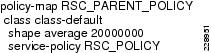
interface Serial2/0dampeningip address 10.126.0.4 255.255.255.254ip authentication mode eigrp 100 md5ip authentication key-chain eigrp 100 eigrp-keyip pim sparse-modeservice-policy output RSC_PARENT_POLICYip summary-address eigrp 100 10.124.0.0 255.255.0.0 5load-interval 30carrier-delay msec 0dsu bandwidth 44210Routing Design
This section discusses how routing is designed and implemented in the Medium Enterprise Design Profile. As indicated in the WAN transport design, the Medium Enterprise Design Profile has multiple transports—Private WAN, Internet, Metro Service, and leased-line services. The private network would provide access to reach other remote sites globally. Internet service would help the medium enterprise to reach Internet. Metro/leased-line service would help to connect remote site locations to the main site. To provide connectivity using these transport services we have designed two distinct routing domains - external and internal. The external routing domain is where the medium enterprise would connect with external autonomous system, and the internal routing domain is where the entire routing domain is within single autonomous system. The following section discusses about the external routing domain design, and the internal routing domain design.
External Routing Domain
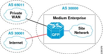
As indicated above, the external routing domain would connect with different service providers, Private WAN, and the Internet service. This is applicable only to the WAN aggregation router 1, which interfaces with both Private WAN, and the Internet service, because it the only router which interfaces with the external domain.
The main design considerations for routing for the Internet/private WAN edge router are as follows:
•
•
•
To meet the above requirements, BGP has is chosen as the routing protocol because of the following reasons:
•
•
Figure 3-8 BGP Design in Medium Enterprise
For more information on designing and configuring BGP on the Internet border router, refer to the SAFE Reference Design at the following link:
http://www.cisco.com/en/US/netsol/ns954/index.html#~five
Internal Routing Domain
EIGRP is chosen as the routing protocol for designing the internal routing domain, which is basically connecting all the devices in the site network. EIGRP is a balanced hybrid routing protocol that builds neighbor adjacency and flat routing topology on per autonomous-system (AS)-basis. It is important to design EIGRP routing domain in site infrastructure with all the design principles defined earlier in this section. The Medium Enterprise Design Profile network infrastructure must be deployed in recommended EIGRP protocol design to secure, simplify, and optimize the network performance. Figure 3-9 depicts the design of EIGRP for internal network.
Figure 3-9 EIGRP Design Diagram
EIGRP Configuration on WAN Aggregation Router2 -ASR1006
The EIGRP is used on the following links:
1.
2.
3.
4.
Step 1
interface Port-channel1ip address 10.125.0.23 255.255.255.254ip authentication mode eigrp 100 md5ip authentication key-chain eigrp 100 eigrp-key!interface GigabitEthernet0/2/0description Connected to cr11-3750ME-RLCip address 10.126.0.1 255.255.255.254ip authentication mode eigrp 100 md5ip authentication key-chain eigrp 100 eigrp-key!interface GigabitEthernet0/2/1description Connected to cr11-4507-RMCdampeningno ip addressload-interval 30carrier-delay msec 0negotiation autocdp enablehold-queue 2000 inhold-queue 2000 out!interface GigabitEthernet0/2/1.102encapsulation dot1Q 102ip address 10.126.0.3 255.255.255.254ip authentication mode eigrp 100 md5ip authentication key-chain eigrp 100 eigrp-key!interface Serial0/3/0dampeningip address 10.126.0.5 255.255.255.254ip authentication mode eigrp 100 md5ip authentication key-chain eigrp 100 eigrp-keyStep 2
interface Port-channel1ip address 10.125.0.23 255.255.255.254ip summary-address eigrp 100 10.126.0.0 255.255.0.0 5!interface GigabitEthernet0/2/0description Connected to cr11-3750ME-RLCip address 10.126.0.1 255.255.255.254ip summary-address eigrp 100 10.126.0.0 255.255.0.0 5!interface GigabitEthernet0/2/1description Connected to cr11-4507-RMC!interface GigabitEthernet0/2/1.102encapsulation dot1Q 102ip address 10.126.0.3 255.255.255.254ip summary-address eigrp 100 10.126.0.0 255.255.0.0 5!interface Serial0/3/0ip address 10.126.0.5 255.255.255.254ip summary-address eigrp 100 10.126.0.0 255.255.0.0 5Step 3
router eigrp 100network 10.0.0.0eigrp router-id 10.125.200.24no auto-summarypassive-interface defaultno passive-interface GigabitEthernet0/2/0no passive-interface GigabitEthernet0/2/1.102no passive-interface Serial0/3/0no passive-interface Port-channel1nsfThe ASR1006 router is enabled with nonstop forwarding feature. The following command is used to verify the status:
cr11-asr-we#show ip protocols*** IP Routing is NSF aware ***Routing Protocol is "eigrp 100"Outgoing update filter list for all interfaces is not setIncoming update filter list for all interfaces is not setDefault networks flagged in outgoing updatesDefault networks accepted from incoming updatesEIGRP metric weight K1=1, K2=0, K3=1, K4=0, K5=0EIGRP maximum hopcount 100EIGRP maximum metric variance 1Redistributing: eigrp 100EIGRP NSF-aware route hold timer is 240sEIGRP NSF enabledNSF signal timer is 20sNSF converge timer is 120sTime since last restart is 2w1dAutomatic network summarization is not in effectAddress Summarization:10.126.0.0/16 for Port-channel1, GigabitEthernet0/2/0, GigabitEthernet0/2/1.102Serial0/3/0Summarizing with metric 2816Maximum path: 4Routing for Networks:10.0.0.0Passive Interface(s):GigabitEthernet0/2/1GigabitEthernet0/2/2GigabitEthernet0/2/3GigabitEthernet0/2/4Serial0/3/1Group-Async0Loopback0Tunnel0Routing Information Sources:Gateway Distance Last Update(this router) 90 2w1d10.125.0.22 90 1d17h10.126.0.4 90 1d17h10.126.0.0 90 1d17h10.126.0.2 90 1d17hDistance: internal 90 external 170cr11-asr-we#EIGRP Configuration on 3750 Large Remote Site Switch
The EIGRP configuration at the 3750 large remote site also has similar steps compared to main site.
Step 1
interface GigabitEthernet1/1/1description Connected to cr11-ASR-WEno switchportdampeningip address 10.126.0.0 255.255.255.254ip authentication mode eigrp 100 md5ip authentication key-chain eigrp 100 eigrp-keyrouter eigrp 100network 10.0.0.0passive-interface defaultno passive-interface Port-channel1no passive-interface GigabitEthernet1/1/1eigrp router-id 10.122.200.1Step 2
interface GigabitEthernet1/1/1description Connected to cr11-ASR-WEno switchportdampeningip address 10.126.0.0 255.255.255.254ip summary-address eigrp 100 10.122.0.0 255.255.0.0Step 3
router eigrp 100network 10.0.0.0passive-interface defaultno passive-interface Port-channel1no passive-interface GigabitEthernet1/1/1eigrp router-id 10.122.200.1!EIGRP Configuration at 4750 Medium Site Switch
Step 1
interface Vlan102description Connected to cr11-ASR-WEdampeningip address 10.126.0.2 255.255.255.254ip authentication mode eigrp 100 md5ip authentication key-chain eigrp 100 eigrp-keyStep2) Enable summarization on the WAN linksinterface Vlan102ip summary-address eigrp 100 10.123.0.0 255.255.0.0 5load-interval 30carrier-delay msec 0Step 2
router eigrp 100passive-interface defaultno passive-interface Vlan102no auto-summaryeigrp router-id 10.123.200.1network 10.98.0.1 0.0.0.0network 10.123.0.0 0.0.255.255network 10.126.0.0 0.0.255.255nsf!EIGRP Configuration at 3800 Small Remote Site Router
Step 1
interface Serial2/0dampeningip address 10.126.0.4 255.255.255.254ip authentication mode eigrp 100 md5ip authentication key-chain eigrp 100 eigrp-keyStep2) Configure Summarizationinterface Serial2/0dampeningip summary-address eigrp 100 10.124.0.0 255.255.0.0 5load-interval 30carrier-delay msec 0dsu bandwidth 44210Step 2
router eigrp 100network 10.0.0.0no auto-summaryeigrp router-id 10.124.200.1!To obtain more information about EIGRP design, refer to the "Designing an End-to-End EIGRP Routing Network" section on page 2-52.
QoS
QoS is a part of foundation services, which is very critical to the application performance. The traditional applications such as voice, video, and data together with newer applications such as broadcast video, real-time video, video surveillance, and many other applications have all converged into IP networks. Moreover, each of these applications require different performance characteristics on the network. For example, data applications may need only high throughput, but are tolerant to delay and loss. Similarly, voice applications need constant low bandwidth and low delay performance. To cater to these performance characteristics, Cisco IOS has several robust QoS tools such as classification and marking, queuing, WRED, policing, shaping, and many other tools to effect the traffic characteristics. Before discussing the QoS design, the following subsection provides a brief introduction on these characteristics.
Traffic Characteristics
The main traffic characteristics are bandwidth, delay, loss, and jitter.
•
Figure 3-10 Bandwidth Constraint Due to Difference in Speeds
•
•
•
QoS Design for WAN Devices
For any application regardless of whether it is video, voice, or data, the traffic characteristics discussed above need to be fully understood before making any decisions on WAN transport or the platforms needed to deploy these services. Cisco QoS tools help to optimize these characteristics so that voice, video, and data applications performance is optimized. The voice and video applications are highly delay-and drop-sensitive, but the difference lies in the bandwidth requirement. The voice applications have a constant and low bandwidth requirement, but the video applications have variable bandwidth requirements. Therefore, it is important to have a good QoS policy to accommodate these applications.
Regardless of the WAN transport chosen, QoS design is the most significant factor in determining the success of network deployment. There are many benefits in deploying a consistent, coherent QoS scheme across all network layers. It helps not only in optimizing the network performance, it helps to mitigate network attacks and manage the control plane traffic. Therefore, when the platforms are selected at each network layer, QoS must always be considered in the design choice.
In the WAN links, the congestion can occur when there are speed mismatches. This may occur because there is significant difference between LAN speeds and WAN speeds. To prevent that from occurring, the following two major tools can be used:
•
•
The general guidelines for deploying the WAN edge device considerations are as follows:
•
•
When designing the QoS for WAN architecture, there are two main considerations to start with:
•
•
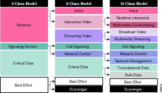
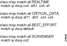
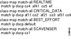
This document assumes that the service provider will support at least 4 classes of traffic such as REAL_TIME, GOLD, SILVER, and DEFAULT. The Medium Enterprise site LAN supports 12 classes of traffic, which will be mapped to 4 classes of traffic on the WAN side. Figure 3-11 illustrates the recommended markings for different application traffic.
Figure 3-11 Mapping of 12-Class Model to 4-Classes
Once the QoS policy is designed, the next pertinent question is the appropriate allocation of bandwidth for the 4 classes of traffic. Table 3-1 describes the different classes, the percentage, and actual bandwidth allocated for each class of traffic.
QoS Implementation
This section discusses how QoS is implemented in Medium Enterprise Design Profile. As explained in the QoS design considerations, the main objective of the QoS implementation is to ensure that the 12 classes of LAN traffic is mapped into 4 classes of WAN traffic. Each class should receive the adequate bandwidth, and during congestion, each class must received the guaranteed minimum bandwidth. To accomplish this objective, the following methods are used to implement QoS policy:
•
•
•
This section describes detailed implementation of QoS policies at various parts of the network. The devices that need QoS design are as follows:
•
•
•
•
•
QoS Implementation at WAN Aggregation Router 1
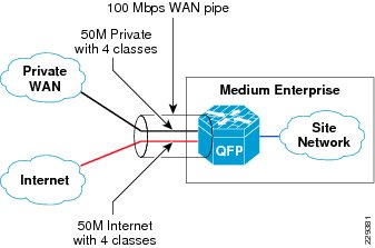
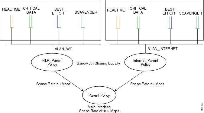
The WAN aggregation router 1 connects to two different providers: private WAN network and Internet. It is assumed that the aggregate bandwidth is 100Mbps that should be shared between both services—50Mbps is dedicated for private WAN network and 50Mbps is dedicated for Internet traffic. As explained in the previous section, to implement this granular policy, a three-layer hierarchical QoS design needs to be used.
Figure 3-12 depicts the bandwidth allocation at the WAN aggregation router 1.
Figure 3-12 The Bandwidth Allocation at WAN Aggregation Router 1
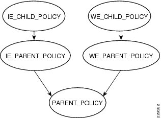
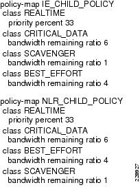
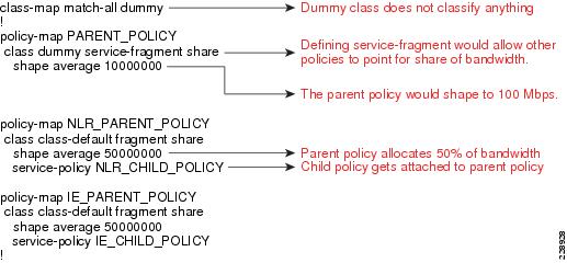
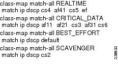
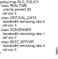
To implement a three-layer hierarchical QoS policy on the WAN aggregation1 router, a higher-level parent policy is defined that would shape the aggregate WAN speed to 100Mbps, then subparent policies are defined, which would further shape it to 50Mbps. Within each of the subparent policies, there are four defined classes: REALTIME, CRITICAL_DATA, BEST_EFFORT, and SCAVENGER classes. Figure 3-13 depicts this hierarchical QoS design.
Figure 3-13 Hierarchical QoS Design
The hierarchical three-layer QoS policy is implemented in three steps as follows:
Step 1
Step 2
Step 3
Implementation Steps for QoS Policy at WAN Aggregation Router 1
This section would describes the detailed steps needed to implement the three-layer QoS policy in the WAN_Aggregation_router1.
Step 1
Step 2
Step 3
Step 4
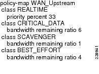
QoS Policy Implementation for WAN Aggregation Router 2
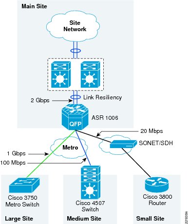
QoS configuration at WAN aggregation router 2 is more complex than the QoS configuration of WAN aggregation router 1 because of different speeds connected to the router. Figure 3-14 depicts the different types of WAN speeds
Figure 3-14 WAN Link Speeds at WAN Aggregation Router 2 Device
The requirements of the QoS design at the WAN aggregation router 2 are as follows:
•
•
•
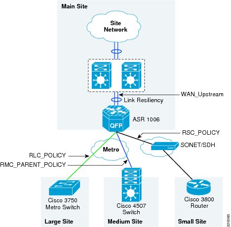
Table 3-2 describes the different QoS policy names applied at the WAN aggregation router 2.
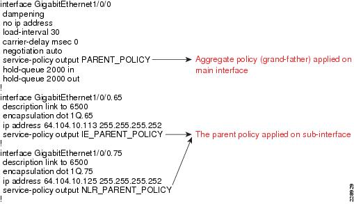
Figure 3-15 depicts the various points where QoS policies are applied.
Figure 3-15 The allocation of QoS Policy at Different Places on WAN Aggregation Router 2
QoS Policy Between the Main Site and Large Remote Site
The WAN physical link speed is 1Gbs. Also, the actual SLA between the main site and the large remote site is assumed to be 1Gbps. Therefore, a single-layer QoS policy is implemented in this scenario.
Step 1
Step 2
Step 3
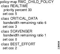
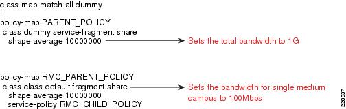
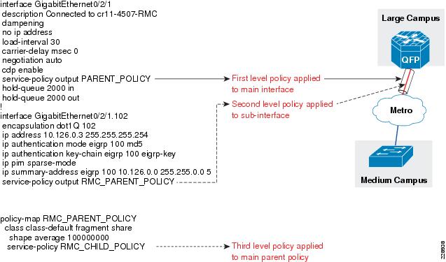
QoS Policy Between the Main Site and Medium Remote Site Location
A three-layer QoS design is needed between the main site and large remote medium site location, because there could be a couple of remote medium site locations connected on a single metro link to the main site. Figure 3-16 shows how this design looks like when there are more than one remote medium site.
Figure 3-16 The WAN Link Design for Connectivity Between Main Site and Medium Remote Site
Here, the implementation details are provided for only a single medium site location; however, more medium site locations could be added, if desired.
The following are implementation steps for this QoS policy:
Step 1
Step 2
Step 3
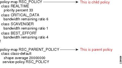
QoS Policy Between Main Site and Small Remote Site Location
The following is the QoS policy implementation steps between main site and small remote site location. The actual WAN speed is 44Mbps; however, the SLA is assumed to be 20Mbps. Therefore, a two-layer hierarchical QoS design is needed to implement the above policy.
Step 1
Step 2
QoS Policy Implementation Between the Main Site and Core
The following is the QoS policy implementation between main site and core. There are two links between the ASR 1006 and core, which is VSS. QoS policy needs to be configured on both links.
Step 1
Step 2
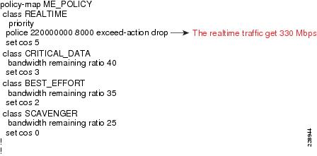
QoS Policy Between Large Remote Site and Main Site Location
The WAN interface between the large remote site and main site is 1 Gbps, which is also equal to the link speed; therefore, a single-layer QoS policy map can be created.
Step 1
Step 2
Step 3
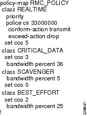
QoS Policy Between Remote Medium Site and Main Site Location
The remote medium site location uses 4500 as WAN device, which uses 4500-E supervisor. The physical link speed is 100Mbps and the actual SLA is also 100Mbps. Therefore, a single-layer QoS policy meets the requirement.
Step 1
Step 2
Step 3
QoS Policy Implementation Between Small Remote Site and Main Site Location
This section describes the QoS policy implementation between the small remote site location and the main site. The physical link speed is T3, which is 45Mbps, but the SLA is 20 Mbps. Therefore, a hierarchical two-layer QoS policy is implemented. The parent policy shapes the link speed to 20Mbps and the child policy would queue and allocate the bandwidth within the 20Mbps.
Step 1
Step 2
Step 3
Step 4
Redundancy
Redundancy must be factored into the WAN design for a number of reasons. Since the WAN may span across several service provider networks, it is likely that network will be subjected to different kinds of failures occurring all the time. Some of the following failures can occur over a period of time: route flaps, brownouts, fibers being cut, and device failures. The probability of these occurring over a short period of time is low, but the occurrence is highly likely over a long period of time. To meet these challenges, different kind of redundancy should be planned. The following are some of the ways to support redundancy:
•
•
•
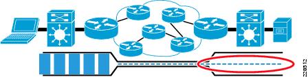
Figure 3-17 Link Resiliency
Table 3-3 shows the various WAN devices that are designed for resiliency.
Table 3-3 WAN Devices
WAN aggregation 1
Private WAN/Internet
ISSU, IOS based redundancy
WAN aggregation 2
Metro
Redundant ESP, RP
This section discusses how to incorporate the resiliency principle in Cisco Medium Enterprise Design Profile for the WAN design. Enabling resiliency adds cost and complexity to the design. Therefore, resiliency has been added at certain places where it is absolutely critical to the network architecture rather than designing redundancy at every place of the network.
In the Cisco Medium Enterprise Design Profile, the redundancy is planned at both WAN aggregation router1 and WAN aggregation router 2 in the main site location. As explained in the "WAN Aggregation Platform Selection in the Medium Enterprise Design Profile" section, ASR routers have been selected at both WAN aggregation locations. However, there are different models at both WAN aggregation locations. When the ASR router interfaces with the private WAN, Internet networks the ASR 1004 with IOS-based redundancy. Similarly, for the ASR router that interfaces with Metro connections, the ASR 1006 with dual RP and dual ESP has been chosen to provide for hardware-based redundancy. Both of these models support In Service Software Upgrade (ISSU) capabilities to allow a user to upgrade Cisco IOS XE Software while the system remains in service. To obtain more information on ASR resiliency capabilities, see the ASR page at following URL: http://www.cisco.com/go/asr1000
Implementing IOS-based Redundancy at WAN Aggregation Router 1
The key requirement for implementing software-based redundancy on the ASR1004 is that it must have 4GB DRAM on ASR1004. The following are steps for implementing the IOS-based redundancy:
Step 1
CR11-ASR-IE#show versionCisco IOS Software, IOS-XE Software (PPC_LINUX_IOSD-ADVENTERPRISE-M), Version 12.2(33)XND3, RELEASE SOFTWARE (fc1)Technical Support: http://www.cisco.com/techsupportCopyright (c) 1986-2010 by Cisco Systems, Inc.Compiled Tue 02-Mar-10 09:51 by mcpreCisco IOS-XE software, Copyright (c) 2005-2010 by cisco Systems, Inc.All rights reserved. Certain components of Cisco IOS-XE software arelicensed under the GNU General Public License ("GPL") Version 2.0. Thesoftware code licensed under GPL Version 2.0 is free software that comeswith ABSOLUTELY NO WARRANTY. You can redistribute and/or modify suchGPL code under the terms of GPL Version 2.0. For more details, see thedocumentation or "License Notice" file accompanying the IOS-XE software,or the applicable URL provided on the flyer accompanying the IOS-XEsoftware.ROM: IOS-XE ROMMONCR11-ASR-IE uptime is 3 weeks, 6 days, 2 hours, 4 minutesUptime for this control processor is 3 weeks, 6 days, 2 hours, 6 minutesSystem returned to ROM by SSO Switchover at 14:41:38 UTC Thu Mar 18 2010System image file is "bootflash:asr1000rp1-adventerprise.02.04.03.122-33.XND3.bin"Last reload reason: redundancy force-switchovercisco ASR1004 (RP1) processor with 736840K/6147K bytes of memory.5 Gigabit Ethernet interfaces32768K bytes of non-volatile configuration memory.4194304K bytes of physical memory.937983K bytes of eUSB flash at bootflash:.39004543K bytes of SATA hard disk at harddisk:.15641929K bytes of USB flash at usb1:.Configuration register is 0x2102CR11-ASR-IE#Step 2
redundancymode sso!Step 3
CR11-ASR-IE#show redunCR11-ASR-IE#show redundancyRedundant System Information :------------------------------Available system uptime = 3 weeks, 6 days, 2 hours, 11 minutesSwitchovers system experienced = 3Standby failures = 0Last switchover reason = active unit removedHardware Mode = DuplexConfigured Redundancy Mode = ssoOperating Redundancy Mode = ssoMaintenance Mode = DisabledCommunications = UpCurrent Processor Information :-------------------------------Active Location = slot 7Current Software state = ACTIVEUptime in current state = 3 weeks, 6 days, 2 hours, 0 minutesImage Version = Cisco IOS Software, IOS-XE Software (PPC_LINUX_IOSD-ADVENTERPRISE-M), Version 12.2(33)XND3, RELEASE SOFTWARE (fc1)Technical Support: http://www.cisco.com/techsupportCopyright (c) 1986-2010 by Cisco Systems, Inc.Compiled Tue 02-Mar-10 09:51 by mcpreBOOT = bootflash:asr1000rp1-adventerprise.02.04.03.122-33.XND3.bin,1;CONFIG_FILE =Configuration register = 0x2102Peer Processor Information :----------------------------Standby Location = slot 6Current Software state = STANDBY HOTUptime in current state = 3 weeks, 6 days, 1 hour, 59 minutesImage Version = Cisco IOS Software, IOS-XE Software (PPC_LINUX_IOSD-ADVENTERPRISE-M), Version 12.2(33)XND3, RELEASE SOFTWARE (fc1)Technical Support: http://www.cisco.com/techsupportCopyright (c) 1986-2010 by Cisco Systems, Inc.Compiled Tue 02-Mar-10 09:51 by mcpreBOOT = bootflash:asr1000rp1-adventerprise.02.04.03.122-33.XND3.bin,1;CONFIG_FILE =Configuration register = 0x2102CR11-ASR-IE#Implementation of Hardware-based Redundancy at WAN Aggregation Router 2
As explained in the design considerations documents, the WAN aggregation router 2 has redundant RPs and redundant ESPs. Therefore, with this configuration, we nonstop forwarding of data can be achieved even when there are failures with either ESP or RPs. The following steps are needed to enable hardware redundancy on WAN aggregation router 2:
Step 1
redundancymode ssoStep 2
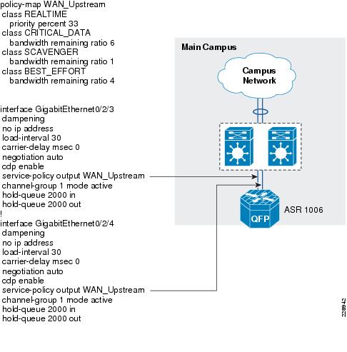
cr11-asr-we#show redundancyRedundant System Information :------------------------------Available system uptime = 3 weeks, 6 days, 3 hours, 32 minutesSwitchovers system experienced = 4Standby failures = 0Last switchover reason = active unit removedHardware Mode = DuplexConfigured Redundancy Mode = ssoOperating Redundancy Mode = ssoMaintenance Mode = DisabledCommunications = UpCurrent Processor Information :-------------------------------Active Location = slot 6Current Software state = ACTIVEUptime in current state = 2 weeks, 1 day, 19 hours, 3 minutesImage Version = Cisco IOS Software, IOS-XE Software (PPC_LINUX_IOSD-ADVENTERPRISEK9-M), Version 12.2(33)XND2, RELEASE SOFTWARE (fc1)Technical Support: http://www.cisco.com/techsupportCopyright (c) 1986-2009 by Cisco Systems, Inc.Compiled Wed 04-Nov-09 18:53 by mcpreBOOT =CONFIG_FILE =Configuration register = 0x2102Peer Processor Information :----------------------------Standby Location = slot 7Current Software state = STANDBY HOTUptime in current state = 2 weeks, 1 day, 18 hours, 52 minutesImage Version = Cisco IOS Software, IOS-XE Software (PPC_LINUX_IOSD-ADVENTERPRISEK9-M), Version 12.2(33)XND2, RELEASE SOFTWARE (fc1)Technical Support: http://www.cisco.com/techsupportCopyright (c) 1986-2009 by Cisco Systems, Inc.Compiled Wed 04-Nov-09 18:53 by mcpreBOOT =CONFIG_FILE =Configuration register = 0x2102cr11-asr-we#Implementation of Link Resiliency Between the WAN Aggregation Router 2 and VSS Core
The following are the implementation steps to deploy link resiliency:
Step 1
interface GigabitEthernet0/2/3dampeningno ip addressload-interval 30carrier-delay msec 0negotiation autocdp enableservice-policy output WAN_Upstreamchannel-group 1 mode activehold-queue 2000 inhold-queue 2000 out!interface GigabitEthernet0/2/4dampeningno ip addressload-interval 30carrier-delay msec 0negotiation autocdp enableservice-policy output WAN_Upstreamchannel-group 1 mode activehold-queue 2000 inhold-queue 2000 out!Step 2) Configure the port-channel interfaceinterface Port-channel1ip address 10.125.0.23 255.255.255.254ip authentication mode eigrp 100 md5ip authentication key-chain eigrp 100 eigrp-keyip pim sparse-modeip summary-address eigrp 100 10.126.0.0 255.255.0.0 5logging event link-statusload-interval 30carrier-delay msec 0negotiation auto!Multicast
The main design considerations for multicast are as follows:
•
•
•
•
In the Medium Enterprise Design Profile, it is assumed that multicast traffic would be present only within the site, and not external enterprise/WAN networks. Therefore, the multicast design looks at only between the main site and small remote site locations. The implementation section in the document shows how to enable multicast on the WAN device only. Therefore, to obtain more information about multicast design for site, refer to the"Multicast for Application Delivery" section on page 2-64.
Multicast Configuration on WAN Aggregation Router 2
This section shows how to enable multicast routing, and what interfaces to be enabled with PIM-Sparse mode on the WAN aggregation router 2 that connects to different remote sites.
Step 1
ip multicast-routing distributedStep 2
–
–
–
–
interface Port-channel1ip address 10.125.0.23 255.255.255.254ip pim sparse-modenegotiation auto!interface GigabitEthernet0/2/0description Connected to cr11-3750ME-RLCip address 10.126.0.1 255.255.255.254ip pim sparse-modelogging event link-statusload-interval 30negotiation auto!interface GigabitEthernet0/2/1description Connected to cr11-4507-RMCdampeningno ip addressload-interval 30carrier-delay msec 0negotiation autocdp enablehold-queue 2000 inhold-queue 2000 out!interface GigabitEthernet0/2/1.102encapsulation dot1Q 102ip address 10.126.0.3 255.255.255.254ip pim sparse-mode!!interface Serial0/3/0dampeningip address 10.126.0.5 255.255.255.254ip pim sparse-modeload-interval 30carrier-delay msec 0dsu bandwidth 44210framing c-bitcablelength 10!Step 3) Configure the RP locationip pim rp-address 10.100.100.100Configuration of Multicast on Large Remote Site
This section discusses how to implement multicast on large remote site. The following are implementation steps:
Step 1
ip multicast-routing distributedStep 2
interface GigabitEthernet1/1/1description Connected to cr11-ASR-WEno switchportdampeningip address 10.126.0.0 255.255.255.254ip pim sparse-modehold-queue 2000 inhold-queue 2000 out!Configuration of Multicast on Medium Remote Site
This section discusses on how to implement multicast on medium remote site.
Step 1
ip multicast-routingStep 2
interface Vlan102description Connected to cr11-ASR-WEdampeningip address 10.126.0.2 255.255.255.254ip pim sparse-modeload-interval 30carrier-delay msec 0Configuration of Multicast on Small Remote Site
This section discusses on how to implement multicast on small remote site.
Step 1
ip multicast-routingStep 2
interface Serial2/0dampeningip address 10.126.0.4 255.255.255.254ip pim sparse-modeload-interval 30carrier-delay msec 0dsu bandwidth 44210Step 3
ip pim rp-address 10.100.100.100 Allowed_MCAST_Groups overrideStep 4
ip pim spt-threshold infinityip pim accept-register list PERMIT-SOURCES!ip access-list standard Allowed_MCAST_Groupspermit 224.0.1.39permit 224.0.1.40permit 239.192.0.0 0.0.255.255deny anyip access-list standard Deny_PIM_DM_Fallbackdeny 224.0.1.39deny 224.0.1.40permit any!ip access-list extended PERMIT-SOURCESpermit ip 10.125.31.0 0.0.0.255 239.192.0.0 0.0.255.255deny ip any any!Summary
Designing the WAN network aspects for the Cisco Medium Enterprise Design Profile interconnects the various LAN locations as well as lays the foundation to provide safety and security, operational efficiencies, virtual learning environments, and secure classrooms.
This chapter reviewed the WAN design models recommended by Cisco and where to apply these models within the various locations within a medium enterprise network. Key WAN design principles such as WAN aggregation platform selection, QoS, multicast, and redundancy best practices are discussed for the entire Medium Enterprise Design Profile. Designing the WAN network of a medium enterprise using these recommendations and best practices will establish a network that is resilient in case of failure, scalable for future grown, simplified to deploy and manage, and cost efficient to meet the budget needs of a medium enterprise.