Table Of Contents
Deploying Enhanced Secure Multi-Tenancy into Virtualized Data Centers
Enhanced Secure Multi-Tenancy Overview
Deploying the Cisco Nexus 7000
Hardening the Cisco Nexus 7000
Deploying the Services Chassis
Deploying Services with Redundancy
Integration of Services Chassis
Hardening the Services Chassis
Deploying the Cisco Nexus 5000
QoS Configuration on the Cisco Nexus 5000
Hardening the Cisco Nexus 5000
Deploying the Cisco Nexus 1010 and 1000V
Classification Using the Cisco Nexus 1000V
Deploying Traffic Engineering with MAC-Pinning
Deploying the Cisco Firewall Switching Module in the Network
Deploying the Cisco Adaptive Security Device Manager for Management of Firewall Module
Deploying the Cisco Intrusion Prevention System
Hardening the Cisco Intrusion Prevention System
Installing and Using Cisco IPS Manager Express
Deploying the Cisco Application Control Engine
Hardening the Cisco Application Control Engine
Managing Cisco ACE with Cisco Application Networking Manager
Deploying the Cisco Network Access Module
Configuring the Cisco Virtual Network Access Module as a NetFlow Collector
Deploying Cisco Unified Computing System
Active/Active Configuration Example
Deploying NetApp Operations Manager and Provisioning Manager
Deploying NetApp Virtual Storage Console
Installing and Configuring VMware vSphere
Installing and Configuring Additional VMware Components for ESMT
Add Protection for Virtual Storage Console
Securing VMware vSphere vCenter Server
Virtual Machine OS and Application Binaries
VMware Site Recovery Manager (SRM)
System Monitoring Capabilities
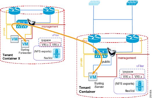
Deploying a Centralized Syslog Server Monitoring
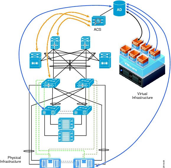
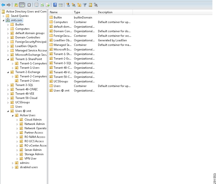
Deploying Centralized Authentication and Access Monitoring
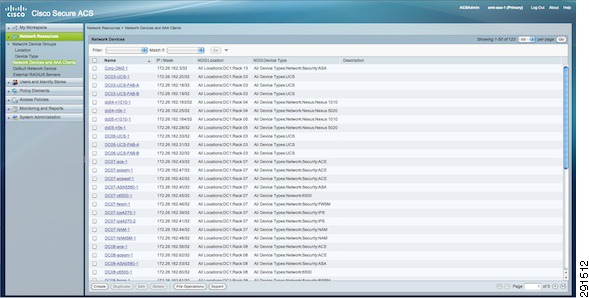
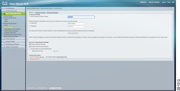
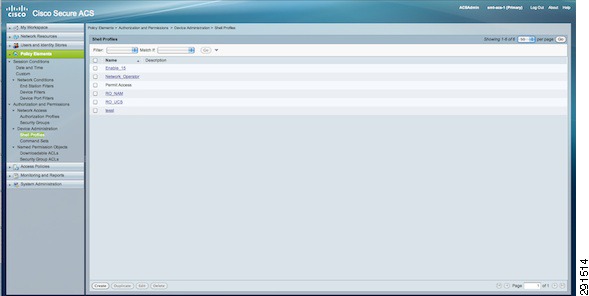
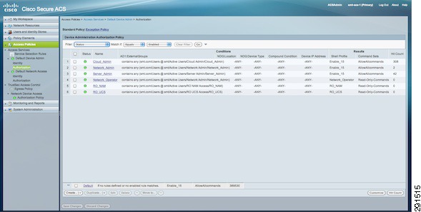
Deploying the Cisco Access Control System
Monitoring Capability with Network Access Module
Monitoring Capability with the Cisco Virtual Network Access Module
Monitoring Traffic Flow through Physical Firewall
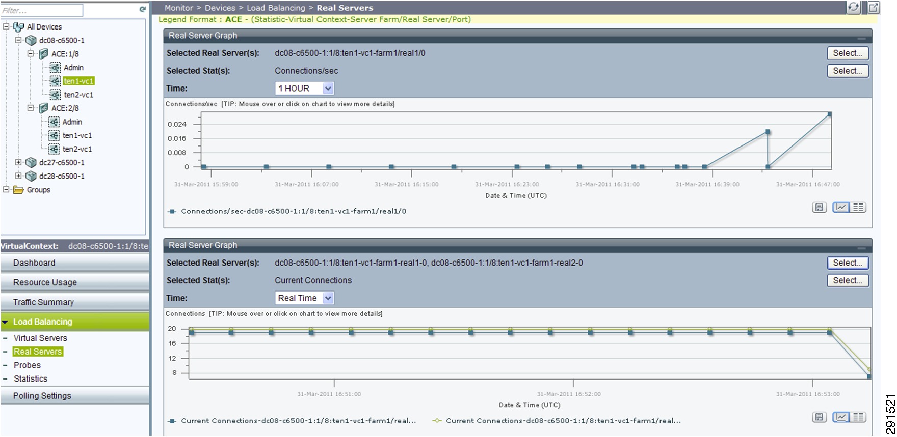
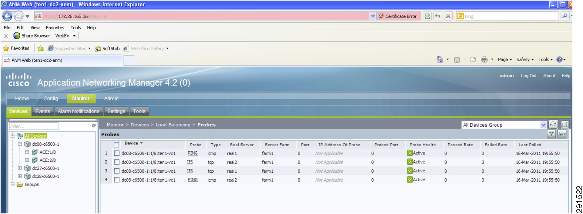
Monitoring Capability of ACE Load Balancer
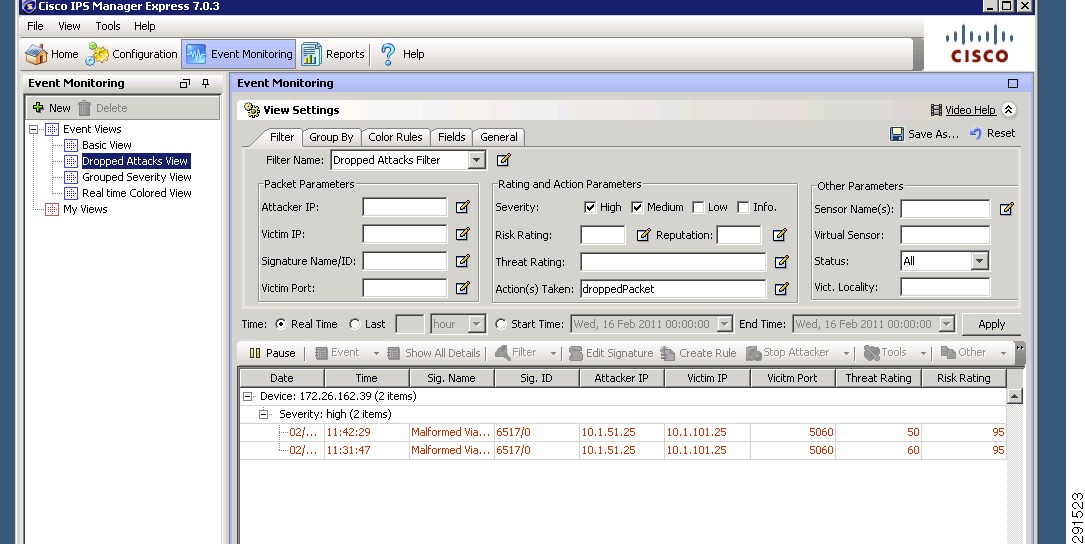
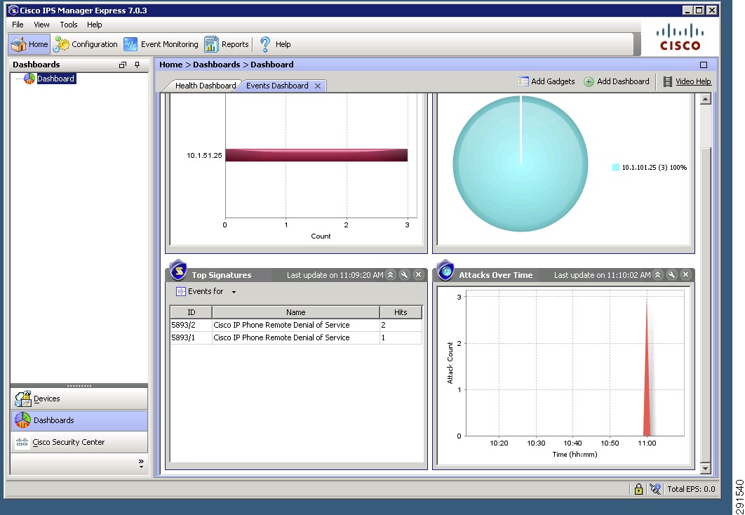
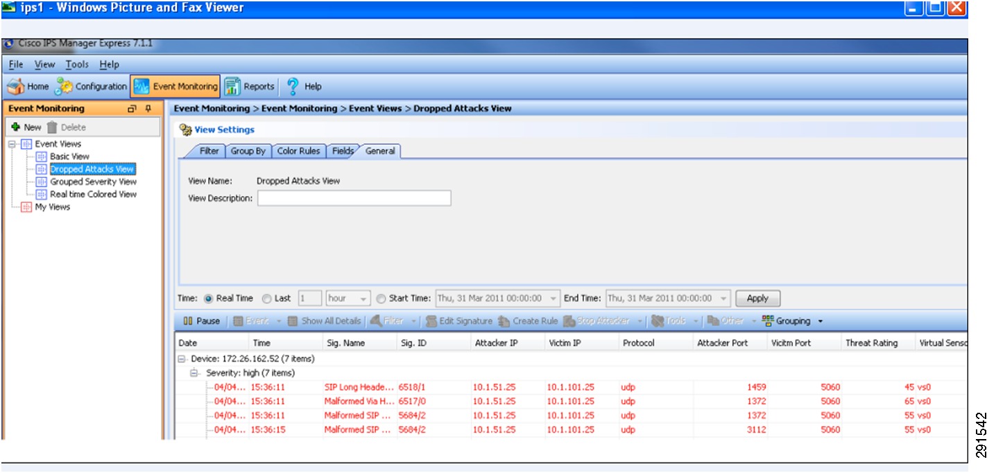
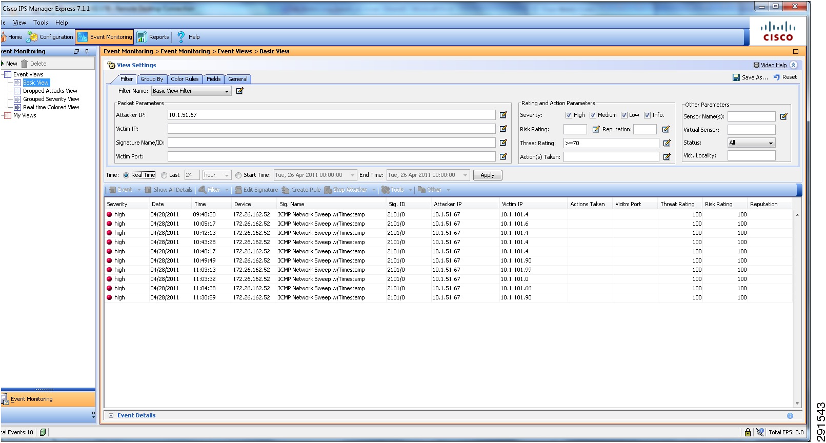
Cisco Intrusion Prevention System Monitoring and Mitigation
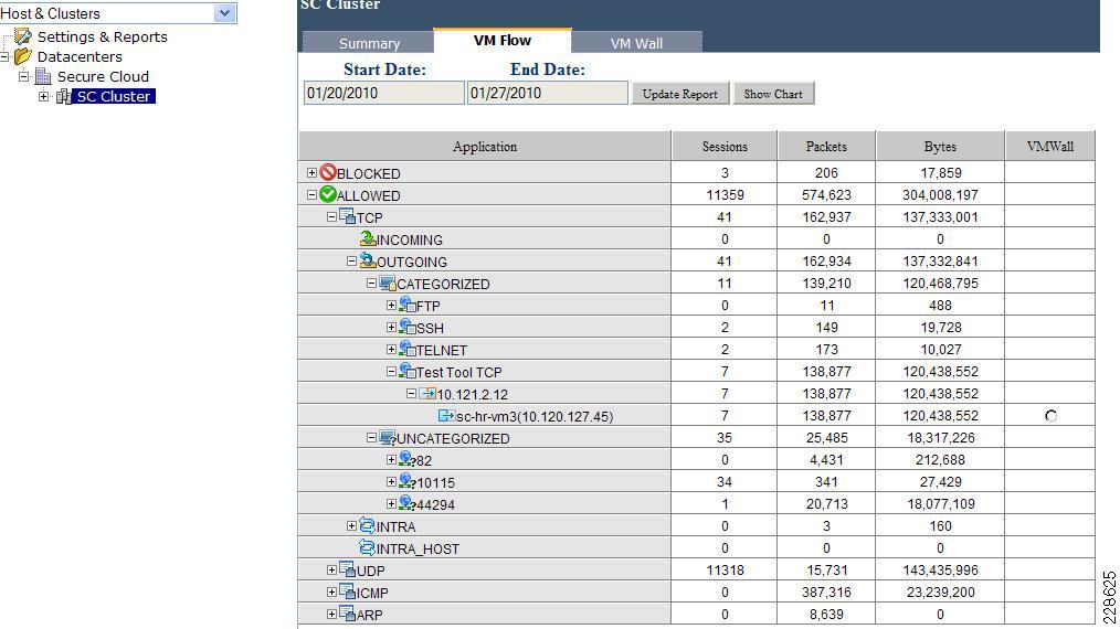
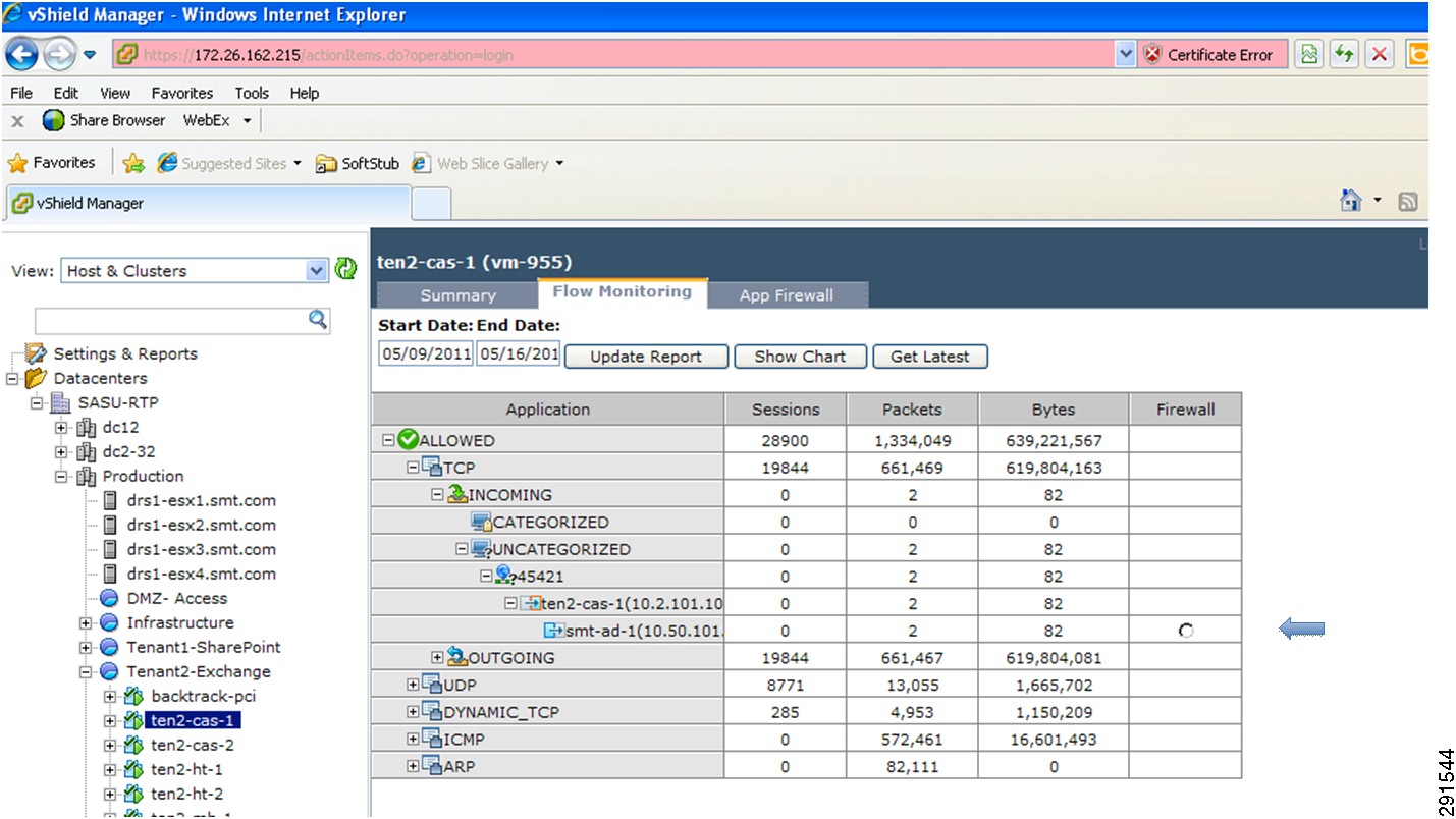
Monitoring Capability Within vShield
Deploying Tenant Resources and Security
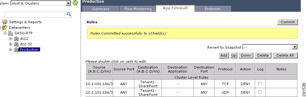
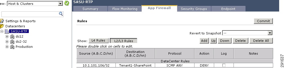
Intra- and Inter-Tenant Traffic Rules
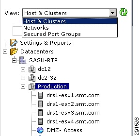
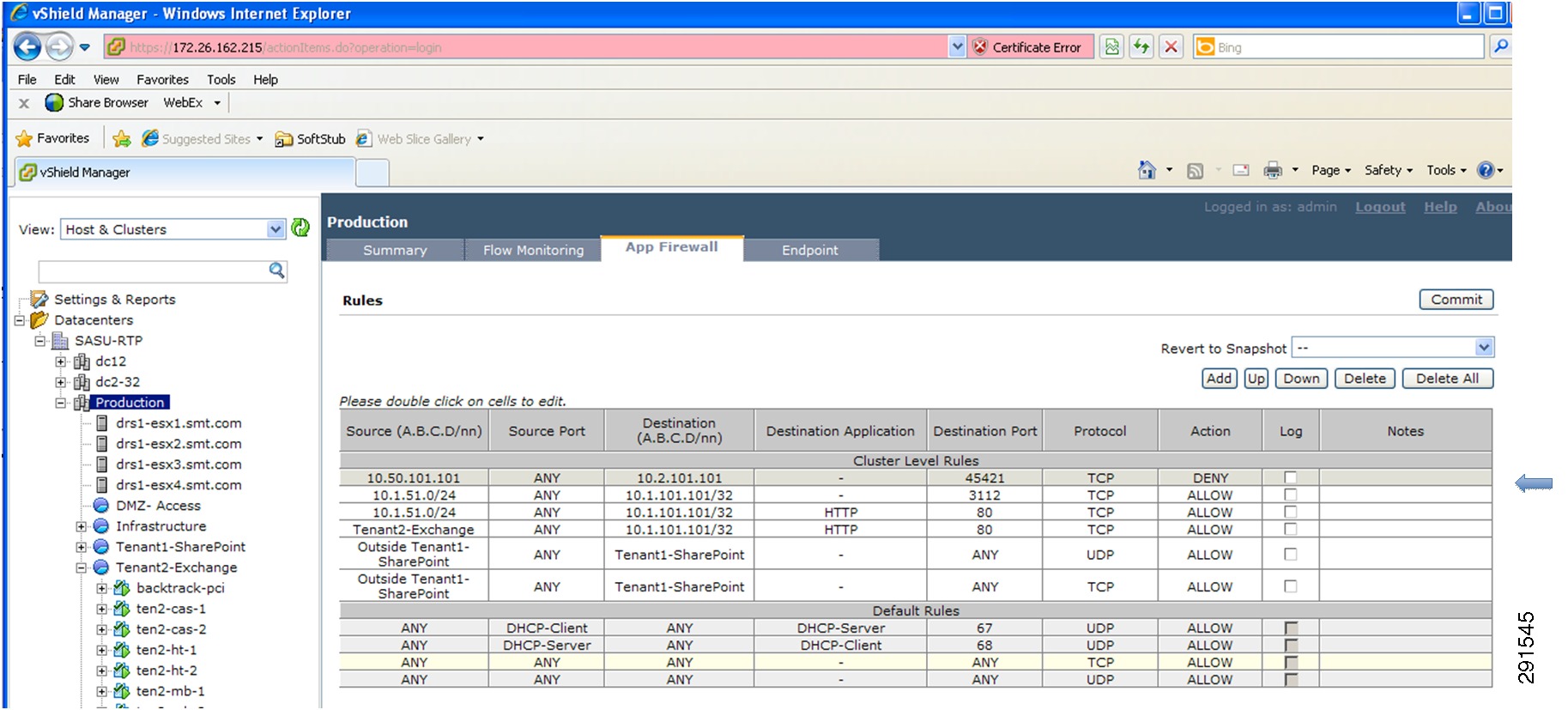
Deploying vShield—Implementing Security Rules at the Access Layer
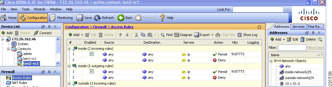
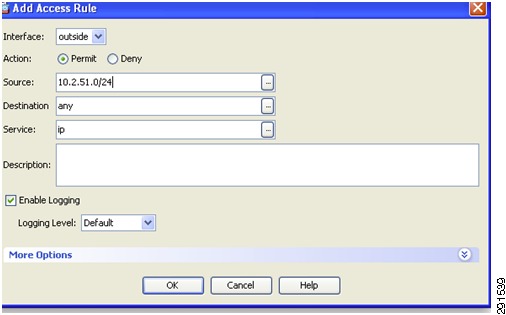
Deploying the Cisco Firewall Switching Module—Implementing Security Rules at Services Layer
Summary of PCI DSS Requirements
Requirement 1—Install and Maintain a Firewall Configuration to Protect Cardholder Environment
Requirement 2—Do Not Use Vendor-Supplied Defaults for System Passwords and other Security Parameters
Requirement 3—Protect Stored Cardholder Data
Requirement 4—Encrypt Transmission of Cardholder Data Across Open, Public Networks
Requirement 5—Use and Regularly Update Anti-Virus Programs
Requirement 6—Develop and Maintain Secure Systems and Applications
Requirement 7—Restrict Access to Cardholder Data by Business Need to Know
Requirement 8—Assign a Unique ID to Each Person with Computer Access
Requirement 9—Restrict Physical Access to Cardholder Data
Requirement 10—Track and Monitor All Access to Network Resources and Cardholder Data
Requirement 11—Regularly Test Security Systems and Processes
Requirement 12—Maintain a Policy that Addresses Information Security for All Personnel
Deploying Enhanced Secure Multi-Tenancy into
Virtualized Data CentersLast Updated: July 7, 2011
Building Architectures to Solve Business Problems
About the Authors
Aeisha Duncan, Technical Marketing Engineer, Systems Architecture and Strategy, Cisco SystemsAeisha Duncan, CCIE #13455, is a Technical Marketing Engineer for data center technologies in Cisco's Systems Architecture and Strategy group. Prior to joining the SASU team, Aeisha spent 4 years as a Customer Support Engineer in Cisco's Technical Assistance Center where she supported LAN switching, VPN and Firewall technologies. She earned a B.S. in Computer Science from the University of Maryland at Baltimore County and an M.S. in Computer Networking from North Carolina State University.
Alex Nadimi, Solutions Architect, Systems Architecture and Strategy, Cisco SystemsAlex has been with Cisco for the past 15 years and is currently working as a Solutions Architect in Cisco Systems Architecture and Strategy group. Prior to this role, he worked as a Technical Marketing Engineer in the Cisco Central Marketing Organization. He has developed solutions and technical guidance on various technologies such as security, VPN networks, WAN transport technologies, data center solutions, and virtualization. Prior to Cisco, he has worked at Hughes LAN Systems and Northern Telecom. He holds a masters of science in electrical engineering from Louisiana State University.
John George, Reference Architect, Infrastructure and Cloud Engineering, NetAppJohn George is a Reference Architect in NetApp's Infrastructure and Cloud Engineering team and is focused on developing, validating, and supporting cloud infrastructure solutions that include NetApp products. Before his current role, he supported and administered Nortel's worldwide training network and VPN infrastructure. John holds a master's degree in computer engineering from Clemson University.
Lindsey Street, Reference Architect, Infrastructure and Cloud Engineering, NetAppLindsey Street is a systems architect in the NetApp Infrastructure and Cloud Engineering team. She focuses on the architecture, implementation, compatibility, and security of innovative vendor technologies to develop competitive and high-performance end-to-end cloud solutions for customers. Lindsey started her career in 2006 at Nortel as an interoperability test engineer, testing customer equipment interoperability for certification. Lindsey has her Bachelors of Science degree in Computer Networking and her Master's of Science in Information Security from East Carolina University.
Mike Zimmerman, Reference Architect, Infrastructure and Cloud Engineering, NetAppMike Zimmerman is a reference architect in NetApp's Infrastructure and Cloud Engineering team. He focuses on the implementation, compatibility, and testing of various vendor technologies to develop innovative end-to-end cloud solutions for customers. Zimmerman started his career at NetApp as an architect and administrator of Kilo Client, NetApp's internal cloud infrastructure, where he gained extensive knowledge and experience building end-to-end shared architectures based upon server, network, and storage virtualization.
Wen Yu, Senior Infrastructure Technologist, VMwareWen Yu is a Sr. Infrastructure Technologist at VMware, with a focus on partner enablement and evangelism of virtualization solutions. Wen has been with VMware for six years during which time four years have been spent providing engineering level escalation support for customers. Wen specializes in virtualization products for continuous availability, backup recovery, disaster recovery, desktop, and vCloud. Wen Yu is VMware, Red Hat, and ITIL certified.
About Cisco Validated Design (CVD) Program
The CVD program consists of systems and solutions designed, tested, and documented to facilitate faster, more reliable, and more predictable customer deployments. For more information visit http://www.cisco.com/go/designzone.
ALL DESIGNS, SPECIFICATIONS, STATEMENTS, INFORMATION, AND RECOMMENDATIONS (COLLECTIVELY, "DESIGNS") IN THIS MANUAL ARE PRESENTED "AS IS," WITH ALL FAULTS. CISCO AND ITS SUPPLIERS DISCLAIM ALL WARRANTIES, INCLUDING, WITHOUT LIMITATION, THE WARRANTY OF MERCHANTABILITY, FITNESS FOR A PARTICULAR PURPOSE AND NONINFRINGEMENT OR ARISING FROM A COURSE OF DEALING, USAGE, OR TRADE PRACTICE. IN NO EVENT SHALL CISCO OR ITS SUPPLIERS BE LIABLE FOR ANY INDIRECT, SPECIAL, CONSEQUENTIAL, OR INCIDENTAL DAMAGES, INCLUDING, WITHOUT LIMITATION, LOST PROFITS OR LOSS OR DAMAGE TO DATA ARISING OUT OF THE USE OR INABILITY TO USE THE DESIGNS, EVEN IF CISCO OR ITS SUPPLIERS HAVE BEEN ADVISED OF THE POSSIBILITY OF SUCH DAMAGES.
THE DESIGNS ARE SUBJECT TO CHANGE WITHOUT NOTICE. USERS ARE SOLELY RESPONSIBLE FOR THEIR APPLICATION OF THE DESIGNS. THE DESIGNS DO NOT CONSTITUTE THE TECHNICAL OR OTHER PROFESSIONAL ADVICE OF CISCO, ITS SUPPLIERS OR PARTNERS. USERS SHOULD CONSULT THEIR OWN TECHNICAL ADVISORS BEFORE IMPLEMENTING THE DESIGNS. RESULTS MAY VARY DEPENDING ON FACTORS NOT TESTED BY CISCO.
The Cisco implementation of TCP header compression is an adaptation of a program developed by the University of California, Berkeley (UCB) as part of UCB's public domain version of the UNIX operating system. All rights reserved. Copyright © 1981, Regents of the University of California.
Cisco and the Cisco Logo are trademarks of Cisco Systems, Inc. and/or its affiliates in the U.S. and other countries. A listing of Cisco's trademarks can be found at http://www.cisco.com/go/trademarks. Third party trademarks mentioned are the property of their respective owners. The use of the word partner does not imply a partnership relationship between Cisco and any other company. (1005R)
Any Internet Protocol (IP) addresses and phone numbers used in this document are not intended to be actual addresses and phone numbers. Any examples, command display output, network topology diagrams, and other figures included in the document are shown for illustrative purposes only. Any use of actual IP addresses or phone numbers in illustrative content is unintentional and coincidental.
Deploying Enhanced Secure Multi-Tenancy into Virtualized Data Centers
© 2011 Cisco Systems, Inc. All rights reserved.
Deploying Enhanced Secure Multi-Tenancy into Virtualized Data Centers
Introduction
Enhanced Secure Multi-Tenancy Overview
The biggest obstacle to adoption of IT as a service (ITaaS) has been lack of confidence that data and applications are securely isolated in a cloud-based infrastructure, where servers, networks, and storage are all shared resources. Cisco®, VMware®, and NetApp® have jointly designed a best-in-breed Enhanced Secure Multi-Tenancy (ESMT) architecture and have validated this design in a lab environment. For more information, see the Enhanced Secure Multi-Tenancy Design Guide (http://www.cisco.com/en/US/docs/solutions/Enterprise/Data_Center/Virtualization/securecldg_V2.html).
This document provides detailed implementation information and examples from a lab-validated reference design. It is structured to provide server, network, and storage architects and engineers with the implementation details to deploy and secure multi-tenant environments on four pillars:
•
Secure separation
•
•
•
Note
FlexPod Overview
FlexPod for VMware is a validated "POD-like" configuration built with technologies and best practices from Cisco, NetApp, and VMware. FlexPod for VMware serves as a base infrastructure platform for many of the applications and solutions that customers deploy today. ESMT is one example of a solution that can be layered on top of FlexPod for VMware. For more information on FlexPod for VMware and the other solutions that can be built on the infrastructure, see FlexPod for VMware Deployment Model (http://www.cisco.com/en/US/docs/solutions/Enterprise/Data_Center/Virtualization/flexpod_vmware.html).
Note
Security Framework
Secure separation within this architecture is implemented at all layers and within most devices. This "defense in depth" approach follows the methodology outlined in Cisco SAFE: A Security Reference Architecture (http://www.cisco.com/en/US/solutions/collateral/ns170/ns896/ns954/white_paper_c11-527476.html).
Deployment Procedures
This section outlines the deployment procedures for the various components and devices of the ESMT architecture. The lab implementation used to validate the ESMT deployment included four tenants:
•
•
•
•
These applications were used to create tenants, however this document does not describe application deployment procedures. The Infrastructure tenant includes commonly shared resources such as Microsoft Active Directory® (AD) and a centralized syslog server.
Deploying the Cisco Nexus 7000
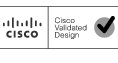
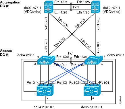
Figure 1 Layer 2 Deployment
Layer 2 Deployment
The Cisco Nexus® 7000 acts as the aggregation layer in the ESMT deployment, so it needs trunked links toward the access layer and the services chassis (Figure 1). The two Cisco Nexus 7000s deployed should be configured as virtual port channel (vPC) peers, with an EtherChannel acting as the vPC peer link. The following configuration snippet is for one peer in the vPC domain:
vpc domain 10role priority 50peer-keepalive destination 10.1.30.102 source 10.1.30.101 vrf vpc-mgmtpeer-gatewayinterface port-channel1description *** Port Channel Between Aggregation - VPC Peer-Link; E1/17, E1/18 ***switchportswitchport mode trunkswitchport trunk native vlan 2switchport trunk allowed vlan 2-3967,4048-4093spanning-tree port type networkmtu 9000vpc peer-linkOnce vPC peering is established, a vPC should be configured going toward the access layer and the services chassis:
interface port-channel45description *** Port Channel Between Aggregation and Access Switches E1/25, E1/26 ***switchportswitchport mode trunkswitchport trunk native vlan 2switchport trunk allowed vlan 2,101,105-111,113,115,119-124,129-130switchport trunk allowed vlan add 132,140,161-162,481,490-493,499-500switchport trunk allowed vlan add 581-586,588-592,599-600,900-902switchport trunk allowed vlan add 905mtu 9000service-policy type queuing input ingress-queuingservice-policy type queuing output egress-policyvpc 45interface port-channel78description *** Port Channel Between Agg and Services - E1/9, E/10 ***switchportswitchport mode trunkswitchport trunk native vlan 2switchport trunk allowed vlan 2,51-53,57,90,99-102,111,116,125switchport trunk allowed vlan add 131-132,161,166,494,586-587,594switchport trunk allowed vlan add 597,902logging event port link-statuslogging event port trunk-statusmtu 9000service-policy type queuing input ingress-queuingservice-policy type queuing output egress-policyvpc 78Layer 3 Deployment
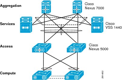
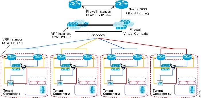
Figure 2 Tenant 1 Topology
The Cisco Nexus 7000 acts as the Layer 3 gateway for all of the tenants. To ensure secure separation between the tenants, a Virtual Routing and Forwarding (VRF) instance is configured for each tenant. There may be multiple Layer 3 interfaces in a VRF instance to service different services and VLANs within a tenant.
vrf context vrf-ten1ip route 0.0.0.0/0 10.1.100.1 ---' Inter-tenant routing goes through FWSM in services chassisinterface Vlan101vrf member vrf-ten1no ip redirectsip address 10.1.101.3/24ip router ospf 1 area 0.0.0.0hsrp version 2hsrp 101authentication text c1sc0preempt delay minimum 180priority 110timers 1 3ip 10.1.101.1no shutdownmtu 9216description **SVI for ten1**interface Vlan102vrf member vrf-ten1no ip redirectsip address 10.1.100.252/24hsrp version 2hsrp 102authentication text c1sc0preempt delay minimum 180timers 1 3ip 10.1.100.254no shutdownmtu 9216description ** FireWall Inside ***interface Vlan106vrf member vrf-ten1no ip redirectsip address 10.1.102.3/24ip ospf passive-interfaceip router ospf 1 area 0.0.0.0hsrp version 2hsrp 106authentication text c1sc0preempt delay minimum 180timers 1 3ip 10.1.102.1no shutdowndescription ** SVI for Tenant 1 Storage Services **interface Vlan107vrf member vrf-ten1no ip redirectsip address 10.1.107.3/25hsrp version 2hsrp 107authentication text c1sc0preempt delay minimum 180priority 110timers 1 3ip 10.1.107.1no shutdowndescription ** SVI for ten1 mgmt **Figure 3 Tenant Model External Traffic Patterns
Inter-tenant routes are not propagated to the tenant VRF instances. Inter-tenant routing is handled by the Cisco Firewall Switching Module (FWSM) deployed in the services chassis. Packets destined to another VRF instance or tenant are routed to the FWSM which, in turn, routes them to the global routing table. Static routes to each VRF instance are added to the global routing table. The routes point to the outside interface of the virtual context on the FWSM that belongs to that particular tenant.
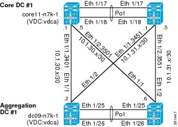
ip route 10.1.101.0/25 10.51.32.1   ---' 10.51.32.1 is the outside interface of the
ten1-vc on the FWSM
Figure 4 Core-Aggregation Connections
To reach clients that are in the VRF instance but not in the local subnets, routing to the core is needed. A trunk with Layer 3 point-to-point links is configured on the links going to both cores. Each point-to-point link belongs to a particular VRF instance/tenant and is used as the gateway to these clients.
interface Ethernet1/1.3401description *** Connection to CORE11-N7K-1 vrf-ten1 ***encapsulation dot1q 3401vrf member vrf-ten1ip flow monitor NETFLOW inputip flow monitor NETFLOW outputip address 10.1.30.2/30ip ospf authenticationip ospf authentication key-chain RoutingAuthip router ospf 1 area 0.0.0.0no shutdownFor most cases, static routing is sufficient for intra- and inter-tenant traffic. For tenants requiring a more robust routing protocol, OSPF is used.
router ospf 1vrf vrf-ten1area 0.0.0.0 range 10.1.101.0/25Hardening the Cisco Nexus 7000
In the following example, the Cisco Nexus 7000 can be hardened to allow access only through SSH, FTP, and ICM in the inbound access list. The outbound access list allows access only to the OOB management network and the inside network. More information on the Cisco Nexus 7000 security capabilities and general hardening guidance can be found at: http://www.cisco.com/en/US/docs/switches/datacenter/sw/4_2/nx-os/security/configuration/guide/Cisco_Nexus_7000_NX-OS_Security_Configuration_Guide__Release_4.2.pdf.
ip access-list OBB-inbound3 permit tcp 172.26.162.216/32 172.26.162.68/329 permit ip 172.26.162.214/32 172.26.162.68/3210 permit icmp 172.26.162.0/16 172.26.162.68/32 ttl-exceeded20 permit icmp 172.26.162.0/16 172.26.162.68/32 port-unreachable30 permit icmp 172.26.162.0/16 172.26.162.68/32 echo-reply40 permit icmp 172.26.162.0/16 172.26.162.68/32 echo50 permit tcp 172.26.0.0/16 172.26.162.68/32 eq 2260 permit tcp 64.102.0.0/16 172.26.162.68/32 eq 2261 permit tcp 64.0.0.0/8 172.26.162.68/32 eq 2262 permit tcp 10.0.0.0/8 172.26.162.68/32 eq 2270 permit tcp 172.26.162.10/32 eq ftp 172.26.162.68/32 gt 1023 established80 permit tcp 172.26.162.10/32 eq ftp-data 172.26.162.68/32 gt 102390 permit tcp 172.26.162.0/32 gt 1023 172.26.162.68/32 gt 1023 established100 permit udp 172.26.162.0/16 gt 1023 172.26.162.68/32 gt 1023102 permit udp 172.26.162.6/32 any eq ntp103 permit udp 172.26.162.9/32 any eq ntp110 deny ip any any logip access-list OBB-outbound10 permit ip 172.26.162.68/32 172.26.0.0/1620 permit ip 172.26.162.68/32 64.102.0.0/1621 permit ip 172.26.162.68/32 64.0.0.0/822 permit ip 172.26.162.68/32 10.0.0.0/8The access list can be applied to the management interface as follows:
interface mgmt0ip access-group OBB-inbound inip access-group OBB-outbound outvrf member managementip address 172.26.162.68/16Service Assurance Deployment
Queuing and bandwidth control on the Cisco Nexus 7000 is implemented in much the same way as it is implemented on the Cisco Nexus 5000. Egress queuing is used, however ingress queuing can be employed where it is understood that the traffic coming in is marked correctly and trusted. This is the case for this deployment. For bridged traffic CoS is untouched, while for routed traffic DSCP is copied to the CoS value.
You may also have to change the default mapping of cos-to-queue for this platform, as is the case in this deployment. It is changed to more closely resemble the mapping in the Cisco Unified Computing SystemTM (UCS) and Cisco Nexus 5000 so bandwidth allocation can be consistent among the different platforms. The cos-to-queue map must be configured in the default VDC of the Cisco Nexus 7000. Queue names beginning with 8q2t-in-q correspond to ingress queues for 10Gbps ports, while queue names beginning with 1p7q4t-out-q correspond to egress queues for these ports:
DC09-N7K-1# show class-map type queuingType queuing class-maps========================class-map type queuing match-any 8q2t-in-q2Description: Classifier for ingress queue 2 of type 8q2tmatch cos 2class-map type queuing match-any 8q2t-in-q3Description: Classifier for ingress queue 3 of type 8q2tclass-map type queuing match-any 8q2t-in-q4Description: Classifier for ingress queue 4 of type 8q2tmatch cos 4class-map type queuing match-any 8q2t-in-q5Description: Classifier for ingress queue 5 of type 8q2tmatch cos 5class-map type queuing match-any 8q2t-in-q6Description: Classifier for ingress queue 6 of type 8q2tmatch cos 6class-map type queuing match-any 8q2t-in-q7Description: Classifier for ingress queue 7 of type 8q2tclass-map type queuing match-any 8q2t-in-q-defaultDescription: Classifier for ingress default queue of type 8q2tmatch cos 0-1,3class-map type queuing match-any 1p7q4t-out-q2Description: Classifier for egress queue 2 of type 1p7q4tmatch cos 2class-map type queuing match-any 1p7q4t-out-q3Description: Classifier for egress queue 3 of type 1p7q4tclass-map type queuing match-any 1p7q4t-out-q4Description: Classifier for egress queue 4 of type 1p7q4tmatch cos 4class-map type queuing match-any 1p7q4t-out-q5Description: Classifier for egress queue 5 of type 1p7q4tmatch cos 5class-map type queuing match-any 1p7q4t-out-q6Description: Classifier for egress queue 6 of type 1p7q4tmatch cos 6class-map type queuing match-any 1p7q4t-out-q7Description: Classifier for egress queue 7 of type 1p7q4tclass-map type queuing match-any 1p7q4t-out-q-defaultDescription: Classifier for egress default queue of type 1p7q4tmatch cos 0-1,3These class maps can then be used for queuing and bandwidth control service polices to be applied to selected ports:
DC09-N7K-1-vdcA# sh policy-map type queuing ingress-queuingType queuing policy-maps========================policy-map type queuing ingress-queuingclass type queuing 8q2t-in-q2bandwidth percent 25class type queuing 8q2t-in-q4bandwidth percent 15class type queuing 8q2t-in-q5bandwidth percent 20class type queuing 8q2t-in-q6bandwidth percent 15class type queuing 8q2t-in-q-defaultbandwidth percent 25DC09-N7K-1-vdcA# sh policy-map type queuing egress-policyType queuing policy-maps========================policy-map type queuing egress-policyclass type queuing 1p7q4t-out-q2bandwidth percent 25class type queuing 1p7q4t-out-q4bandwidth percent 15class type queuing 1p7q4t-out-q5bandwidth percent 20class type queuing 1p7q4t-out-q-defaultbandwidth percent 25These policies are then applied to ports attaching to the access layer and the core layer:
interface port-channel45description *** Port Channel Between Aggregation and Access Switches E1/25, E1/26 ***switchportswitchport mode trunkswitchport trunk native vlan 2switchport trunk allowed vlan 2,101,105-111,113,115,119-124,129-130switchport trunk allowed vlan add 132,140,161-162,481,490-493,499-500switchport trunk allowed vlan add 581-586,588-592,599-600,900-902switchport trunk allowed vlan add 905mtu 9000service-policy type queuing input ingress-queuingservice-policy type queuing output egress-policyvpc 45DC09-N7K-1-vdcA# sh run int e1/1!Command: show running-config interface Ethernet1/1!Time: Wed May 25 23:32:49 2011version 5.1(3)interface Ethernet1/1description *** DC09-N7K-1 E1/1 To CORE11-N7K-1 E1/1 ***rate-mode dedicated forceudld disableservice-policy type queuing output egress-policyservice-policy type queuing input ingress-queuingno shutdownDeploying the Services Chassis
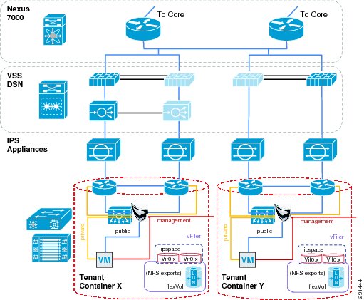
In a multi-tenant environment, different tenants may require different levels of network services security protection. Tenants with very stringent security requirements require a host of virtual and physical appliances to satisfy their needs, while other tenants may require basic network protection. This architecture implements Cisco FWSM, Cisco Application Control Engine (ACE), and Cisco Intrusion Prevention System (IPS) within the services segment of the architecture. It is important to note the flexible nature of this architecture, where the network architect can use any combination of security appliances to create their own security offerings. Some of these offerings are foundational, while the others are optional. Cisco ACE load balancer is considered optional, while it is recommended that IPS and FWSM firewall module be implemented for every tenant, as shown in Figure 5.
Figure 5 Tenant Container Logical Topology
The ACE/FWSM and IPS services are employed external to each tenant's VRF instances. All these services are deployed in Layer 2 transparent mode. Additional information about services integration includes:
•
•
•
•
More information on the specific deployment steps for FWSM, IPS, and ACE are outlined in Deploying the Cisco Firewall Switching Module in the Network, Deploying the Cisco Intrusion Prevention System, and Deploying the Cisco Application Control Engine.
Deploying Services with Redundancy
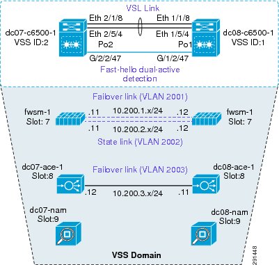
Services can be deployed in a redundant manner. ACE and FWSM can be deployed by using a separate logical link between them within a VSS domain. A VSS domain is used to provide a single services domain with redundant chassis, as shown in Figure 6.
Figure 6 Single Services Domain with VSS
•
•
This allows multiple VLAN interfaces to support multiple virtual contexts.
•
Use this feature when multiple paths exist for the VLAN.
The relevant configuration is:
svclc autostatesvclc multiple-vlan-interfacessvclc switch 1 module 8 vlan-group 8,116,162svclc switch 2 module 8 vlan-group 8,116,162svclc vlan-group 8 2,101-103,111,2003svclc vlan-group 116 116,117svclc vlan-group 162 162firewall autostatefirewall multiple-vlan-interfacesfirewall switch 1 module 7 vlan-group 7,9,116,162firewall switch 2 module 7 vlan-group 7,9,116,162firewall vlan-group 7 51-53,90,99,100,104,125,2001,2002firewall vlan-group 9 57,166,494,586,587,594,597analysis switch 1 module 9 management-port access-vlan 162analysis switch 2 module 9 management-port access-vlan 162Integration of Services Chassis
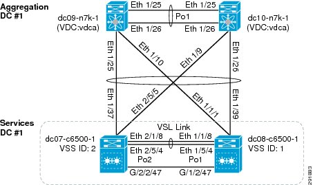
The services chassis is connected to the aggregation layer, as shown in Figure 7.
Figure 7 Aggregation-Services Chassis Connectivity
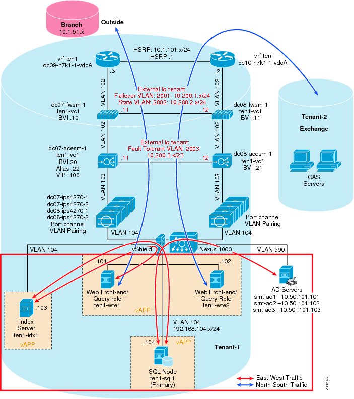
The specific network topology used for validation of the network and services chassis is shown in Figure 8.
Figure 8 SharePoint Tenant Logical Topology
Hardening the Services Chassis
The security hardening deployment steps and general hardening guidelines are defined in:
•
http://www.cisco.com/en/US/solutions/collateral/ns170/ns896/ns954/white_paper_c11-527476.html•
http://www.cisco.com/en/US/docs/solutions/Enterprise/Security/Baseline_Security/securbase.pdfDeploying the Cisco Nexus 5000
The basic Cisco Nexus 5000 configuration can be found in FlexPod for VMware Deployment Model (http://www.cisco.com/en/US/docs/solutions/Enterprise/Data_Center/Virtualization/flexpod_vmware.html). Cisco Nexus 5000 configurations for QoS and security hardening are shown in the sections that follow.
QoS Configuration on the Cisco Nexus 5000
For storage traffic originating on the Cisco Nexus 5000, classification is required to guarantee an acceptable service level for the traffic. This traffic can be classified with a global QoS policy on the Cisco Nexus 5000 and assigned to a system class:
ip access-list classify_COS_510 permit ip 192.168.98.100/32 any20 permit ip 10.49.32.10/32 any30 permit ip any 192.168.98.100/3240 permit ip any 10.49.32.10/32class-map type qos match-any Platinum_Trafficmatch access-group name classify_COS_5policy-map type qos Global_Classify_NFS_Applicationclass Platinum_Trafficset qos-group 2The other CoS values that are configured via port-profiles on the Cisco Nexus 1000V must be put into system classes on the Cisco Nexus 5000 to allow for bandwidth control and queuing within the Cisco Nexus 5000 switching fabric.
class-map type qos match-any Platinum_Trafficmatch access-group name classify_COS_5class-map type qos match-any Gold_Transactionalmatch cos 6class-map type qos match-any Bronze_Transactionalmatch cos 2class-map type qos match-any Silver_Transactionalmatch cos 4class-map type qos match-any Platinum_Transactionalmatch cos 5policy-map type qos Global_Classify_NFS_Applicationclass Platinum_Trafficset qos-group 2class Platinum_Transactionalset qos-group 2class Gold_Transactionalset qos-group 3class Silver_Transactionalset qos-group 4class Bronze_Transactionalset qos-group 5On the Cisco Nexus 5000, a queuing policy is applied globally to the output of all interfaces on the switch. Classification for each qos-group or system class is done by the aforementioned policy-map Global_Classify_NFS_Application.
class-map type queuing Gold_Traffic_Qmatch qos-group 3class-map type queuing class-all-floodmatch qos-group 2class-map type queuing Bronze_Traffic_Qmatch qos-group 5class-map type queuing Silver_Traffic_Qmatch qos-group 4class-map type queuing Platinum_Traffic_Qmatch qos-group 2class-map type queuing class-ip-multicastmatch qos-group 2policy-map type queuing Global_BW_Queuingclass type queuing Platinum_Traffic_Qprioritybandwidth percent 20class type queuing Gold_Traffic_Qbandwidth percent 20class type queuing Silver_Traffic_Qbandwidth percent 20class type queuing Bronze_Traffic_Qbandwidth percent 15class type queuing class-fcoebandwidth percent 15class type queuing class-defaultbandwidth percent 10system qosservice-policy type queuing output Global_BW_QueuingHardening the Cisco Nexus 5000
In the following example, the Cisco Nexus 5000V can be hardened to allow access only through SSH, FTP, and ICM in the inbound access list. The outbound access list allows access only to the OOB management network and the inside network. More information on the Cisco Nexus 5000 security capabilities and general hardening guidance can be found at: http://www.cisco.com/en/US/docs/switches/datacenter/nexus5000/sw/security/502_n2_1m/b_Cisco_n5k_security_config_gd_rel_502_n2_1.pdf.
ip access-list OBB-inbound3 permit tcp 172.26.162.216/32 172.26.162.28/329 permit ip 172.26.162.214/32 172.26.162.28/3210 permit icmp 172.26.162.0/16 172.26.162.28/32 ttl-exceeded20 permit icmp 172.26.162.0/16 172.26.162.28/32 port-unreachable30 permit icmp 172.26.162.0/16 172.26.162.28/32 echo-reply40 permit icmp 172.26.162.0/16 172.26.162.28/32 echo50 permit tcp 172.26.0.0/16 172.26.162.28/32 eq 2260 permit tcp 64.102.0.0/16 172.26.162.28/32 eq 2261 permit tcp 10.0.0.0/8 172.26.162.28/32 eq 2270 permit tcp 172.26.162.10/32 eq ftp 172.26.162.28/32 gt 1023 established80 permit tcp 172.26.162.10/32 eq ftp-data 172.26.162.28/32 gt 102390 permit tcp 172.26.162.0/32 gt 1023 172.26.162.28/32 gt 1023 established100 permit udp 172.26.162.0/16 gt 1023 172.26.162.28/32 gt 1023120 permit tcp 172.26.162.214/32 eq tacacs 172.26.162.28/32ip access-list OBB-outbound10 permit ip 172.26.162.28/32 172.26.0.0/1620 permit ip 172.26.162.28/32 64.102.0.0/1630 permit ip 172.26.162.28/32 10.0.0.0/8The access list can be applied to the management interface as follows
interface mgmt0ip access-group OBB-inbound inip access-group OBB-outbound outip address 172.26.162.28/16Deploying the Cisco Nexus 1010 and 1000V
In this deployment the combination of Cisco Nexus 1010 and Cisco Nexus 1000V are used to implement virtual switching at the access layer. For redundancy a pair of Cisco Nexus 1010 virtual appliances were configured. An active/passive pair of Cisco Nexus 1000V virtual service modules were configured within the Cisco Nexus 1010. All vSphereTM networking is configured to use a Cisco Nexus 1000V virtual switch, including VM, NFS, and vMotion traffic. The Cisco Nexus 1010s are logically connected to the Cisco Nexus 5000 access layer switches, as shown in Figure 9.
Figure 9 Cisco Nexus 1010 Integration and Logical Connectivity
Classification Using the Cisco Nexus 1000V
In this deployment, classification is done on the Cisco Nexus 1000V. Certain port-profiles are marked with a designated CoS value through a service policy attached to the service profile. Any marking done by the host is ignored. This CoS value is in turn trusted by the virtual interface card on the Cisco UCS server blade. CoS values were assigned in the following fashion:
drs1-vsm1# show policy-map Silver_CoS_4Type qos policy-maps====================policy-map type qos Silver_CoS_4class class-defaultset cos 4port-profile type vethernet vMotion_192_168_1vmware port-groupswitchport mode accessswitchport access vlan 901ip flow monitor NFMonitor inputip flow monitor NFMonitor outputservice-policy type qos input Silver_CoS_4no shutdownstate enabledDeploying Traffic Engineering with MAC-Pinning
Mac-pinning is implemented on the Cisco Nexus 1000V to fully utilize the redundant fabric uplinks. Port-profiles assigned to the same CoS value are split evenly between the two uplinks with static mac-pinning.
port-profile type vethernet Exch_NFS_192_168_120vmware port-groupswitchport mode accessswitchport access vlan 120ip flow monitor NFMonitor inputip flow monitor NFMonitor outputservice-policy type qos input Platinum_CoS_5pinning id 0 fl------ Fabric Ano shutdownstate enabledport-profile type vethernet Infra_NFS_192_168_100vmware port-groupswitchport mode accessswitchport access vlan 600ip flow monitor NFMonitor inputip flow monitor NFMonitor outputservice-policy type qos input Platinum_CoS_5pinning id 1 fl-------- Fabric Bno shutdownstate enabledThe uplink port-profile must be configured to honor the mac-pinning and implement dynamic mac-pinning when necessary:
port-profile type ethernet VIC-vm-data-uplinkvmware port-groupswitchport mode trunkswitchport trunk allowed vlan 101,105-107,111,113,115,122,124,132,161,592-593channel-group auto mode on mac-pinning fl------- Mac-pinning enabledno shutdownstate enabledDeploying the Cisco Firewall Switching Module in the Network
The FWSM is logically located between the global interface and the VRF interfaces for each tenant. FWSM is deployed in a bridged mode with different contexts for each tenant. Figure 10 shows the FWSM implemented within the services layer.
Figure 10 Integration of FWSM within Services Layer
The following design principles are implemented in FWSM in the ESMT topology:
•
Each tenant has its own VLAN and associated subnet assignments. For example:
–
–
–
•
Additional services may be positioned but not detailed.
•
•
The basic configuration for tenant-1 (SharePoint) is:
hostname ten1-vc1!interface Vlan104nameif insidesecurity-level 100ip address 10.1.100.1 255.255.255.0 standby 10.1.100.101!interface Vlan51nameif outsidesecurity-level 0ip address 10.51.32.1 255.255.255.0 standby 10.51.32.2!mtu outside 1500mtu inside 1500icmp permit any outsideicmp permit any insideno asdm history enablearp timeout 14400nat-controlstatic (inside,outside) 10.1.101.0 10.1.101.0 netmask 255.255.255.128static (inside,outside) 10.1.100.0 10.1.100.0 netmask 255.255.255.0route outside 0.0.0.0 0.0.0.0 10.51.32.254 1route inside 10.1.101.0 255.255.255.128 10.1.100.254 1Deploying the Cisco Adaptive Security Device Manager for Management of Firewall Module
For information on the steps necessary to deploy the Cisco Adaptive Security Device Manager (ASDM) to mange the firewall module, see: http://www.cisco.com/en/US/docs/security/asdm/6_2/user/guide/asdmug.pdf.
Deploying the Cisco Intrusion Prevention System
The Cisco IPS is deployed as an inline device and a separate context is used for each tenant. The IPS location within the services network is shown in Figure 8. The IPS can be configured using the CLI or the Cisco IPS Device Manager (IDM). In the configuration below, VLAN 103 and 104 are used by the IPS to provide inline intrusion protection within the SharePoint tenant. The CLI configuration is:
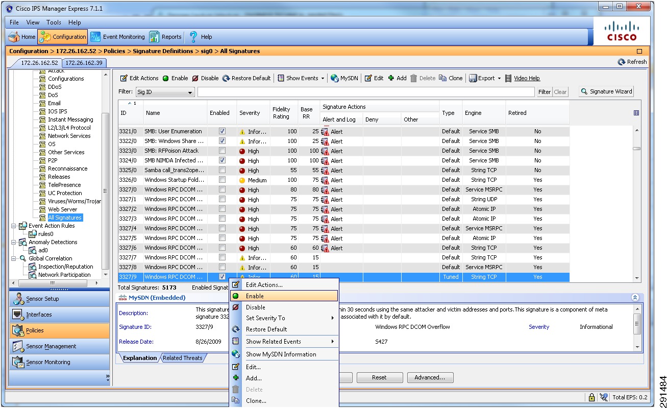
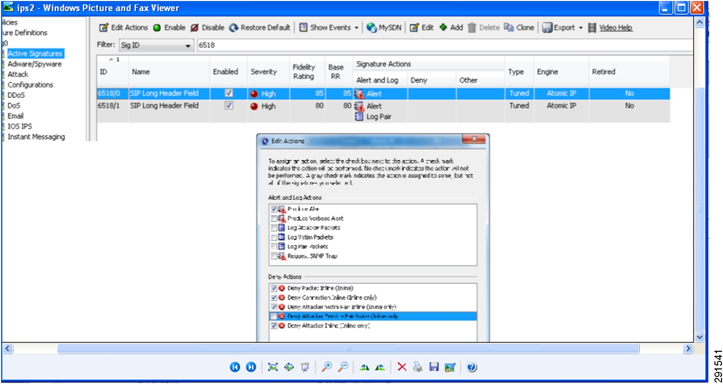
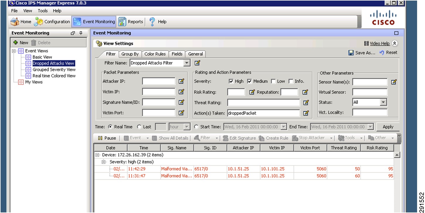
subinterface-type inline-vlan-pairsubinterface 1description to dc07-c6500-1 ten1/2vlan1 103vlan2 104exitexitexitphysical-interfaces TenGigabitEthernet7/1description to dc08-c6500-1 ten1/2admin-state enabledduplex autospeed autodefault-vlan 1alt-tcp-reset-interface nonesubinterface-type inline-vlan-pairsubinterface 1description to dc08-c6500-1 ten1/2vlan1 103vlan2 104exitservice analysis-enginevirtual-sensor vs0description Tenant1 Virtual Sensoranomaly-detectionoperational-mode detectexitphysical-interface TenGigabitEthernet7/0 subinterface-number 1physical-interface TenGigabitEthernet7/1 subinterface-number 1inline-TCP-session-tracking-mode virtual-sensorinline-TCP-evasion-protection-mode strictOnce basic IPS networking parameters are configured, the IPS signatures can be tuned. Figure 11 shows how signatures can be tuned using Cisco IPS Manager Express (IME).
1.
2.
3.
Figure 11 Tuning Signatures Using Cisco IPS Manager Express
For more information on configuring IPS using Cisco IME or CLI, see: http://www.cisco.com/en/US/docs/security/ips/7.0/configuration/guide/ime/ime_interfaces.html.
Hardening the Cisco Intrusion Prevention System
Telnet can be disabled on the management interface and management access can be limited to certain subnets, as shown below.
network-settingshost-ip 172.26.162.52/23,172.26.162.1host-name dc08-ips4270-1telnet-option disabledaccess-list 10.0.0.0/8access-list 64.0.0.0/8access-list 172.0.0.0/8SSH should be configured as a means to access the CLI on IPS4270. The following link outlines the steps to configure SSH and other security parameters: http://www.cisco.com/en/US/docs/security/ips/7.0/configuration/guide/cli/cli_setup.html#wp1035869.
Installing and Using Cisco IPS Manager Express
For information on installing and using Cisco IPS Manager Express, see: http://www.cisco.com/en/US/docs/security/ips/trash/book_files/CLI7_1.pdf.
Deploying the Cisco Application Control Engine
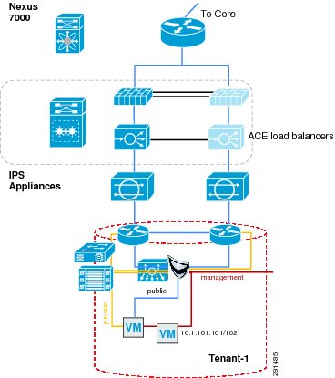
The Cisco ACE module provides load balancing capability. In this deployment, ACE is configured to load balance between two front end servers 10.1.101.101 and 10.1.101.102 within the tenant-1 SharePoint tenant. The virtual interface address (VIP) is 10.1.100.100. ACE is also bridging between VLAN 102 and 103. The configuration for context ten1-vc-1 is shown in Figure 12.
Figure 12 Integration of ACE within Services Layer
The CLI for the ACE configuration is:
dc08-ace-1/Admin# changeto ten1-vc1dc08-ace-1/ten1-vc1# sh running-configGenerating configuration....logging enablelogging buffered 7access-list BPDU ethertype permit bpduaccess-list IPANYANY line 5 extended permit ip any anyaccess-list IPANYANY line 6 extended permit icmp any anyprobe tcp IISinterval 2faildetect 2passdetect interval 10passdetect count 2probe icmp PINGinterval 2faildetect 2rserver host real1ip address 10.1.101.101inservicerserver host real2ip address 10.1.101.102inserviceserverfarm host farm1predictor leastconnsprobe IISprobe PINGrserver real1inservicerserver real2inserviceparameter-map type http PM-REUSEserver-conn reusecase-insensitiveparameter-map type connection timeoutsset tcp timeout embryonic 10set tcp ack-delay 400sticky ip-netmask 255.255.255.255 address both group1timeout 720timeout activeconnsreplicate stickyserverfarm farm1class-map match-all sp-vip2 match virtual-address 10.1.100.100 anypolicy-map type loadbalance first-match lbpolclass class-defaultsticky-serverfarm group1policy-map multi-match LBPOLclass sp-viploadbalance vip inserviceloadbalance policy lbpolloadbalance vip icmp-reply activeconnection advanced-options timeoutsservice-policy input LBPOLinterface vlan 102bridge-group 1access-group input BPDUaccess-group input IPANYANYno shutdowninterface vlan 103bridge-group 1access-group input BPDUaccess-group input IPANYANYno shutdowninterface bvi 1ip address 10.1.100.21 255.255.255.0alias 10.1.100.22 255.255.255.0peer ip address 10.1.100.20 255.255.255.0no shutdownip route 10.1.101.0 255.255.255.0 10.1.100.254ip route 0.0.0.0 0.0.0.0 10.1.100.1Hardening the Cisco Application Control Engine
The ACE management interface can be hardened by implementing a policy map and assigning it to the interface, as shown below. More information on security hardening commands on the ACE module can be found in the Cisco Application Control Engine Administration Guide (http://www.cisco.com/en/US/docs/interfaces_modules/services_modules/ace/vA2_3_0/configuration/administration/guide/ace_adgd.pdf).
class-map type management match-any MANAGEMENT2 match protocol ssh source-address 172.26.0.0 255.255.0.03 match protocol ssh source-address 10.0.0.0 255.0.0.04 match protocol ssh source-address 64.0.0.0 255.0.0.05 match protocol icmp source-address 172.26.0.0 255.255.0.06 match protocol https source-address 64.0.0.0 255.0.0.07 match protocol https source-address 172.0.0.0 255.0.0.08 match protocol https source-address 10.0.0.0 255.0.0.09 match protocol snmp source-address 172.26.0.0 255.255.0.0class-map type management match-all class-Query2 match protocol icmp source-address 10.8.99.0 255.255.255.0policy-map type management first-match MANAGEMENTclass MANAGEMENTpermitpolicy-map type management first-match QUERYclass class-Querypermitinterface vlan 162ip address 172.26.162.56 255.255.0.0peer ip address 172.26.162.43 255.255.0.0service-policy input MANAGEMENTno shutdownAdditional commands configured on the Admin console that pertain to peering and defining tenant contexts are:
interface vlan 162ip address 172.26.162.56 255.255.0.0peer ip address 172.26.162.43 255.255.0.0access-group input IPANYANYservice-policy input MANAGEMENTno shutdownft interface vlan 2003ip address 10.200.3.12 255.255.254.0peer ip address 10.200.3.11 255.255.254.0no shutdownft peer 1heartbeat interval 100heartbeat count 10ft-interface vlan 2003ft group 1peer 1priority 150peer priority 50associate-context Admininservicerole Operatorip route 0.0.0.0 0.0.0.0 172.26.162.1resource-class dc-goldlimit-resource all minimum 0.00 maximum unlimitedlimit-resource sticky minimum 10.00 maximum unlimitedresource-class dc-silverlimit-resource all minimum 0.00 maximum unlimitedresource-class rc-ten1limit-resource all minimum 0.00 maximum unlimitedcontext ten1-vc1description Tenant 1allocate-interface vlan 101-103member dc-goldcontext ten2-vc1description Tenant 2allocate-interface vlan 116-117snmp-server contact "ANM"snmp-server location "ANM"snmp-server community public group Network-Monitorsnmp-server host 172.26.165.36 traps version 2c publicft group 2peer 1priority 150peer priority 50associate-context ten1-vc1inserviceft group 3peer 1priority 150peer priority 50associate-context ten2-vc1inserviceusername admin password 5<>. role Admin domaindefault-domainusername www password 5 <> role Admin domain default-domainssh key rsa 1024 forceManaging Cisco ACE with Cisco Application Networking Manager
For information on Cisco Application Networking Manager (ANM) 4.2, see: http://www.cisco.com/en/US/docs/app_ntwk_services/data_center_app_services/application_networking_manager/4.2/user/guide/ug-book.pdf.
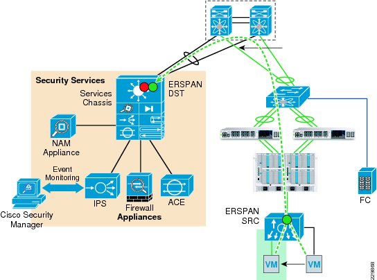
Deploying the Cisco Network Access Module
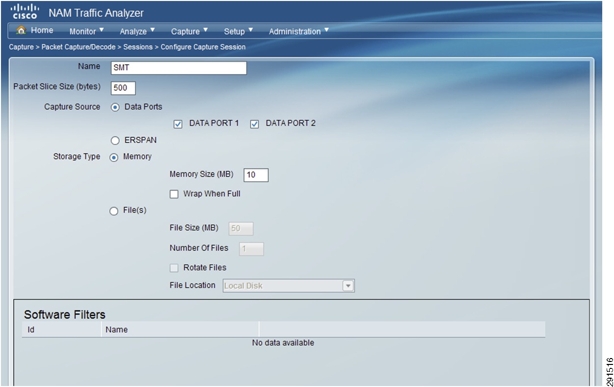
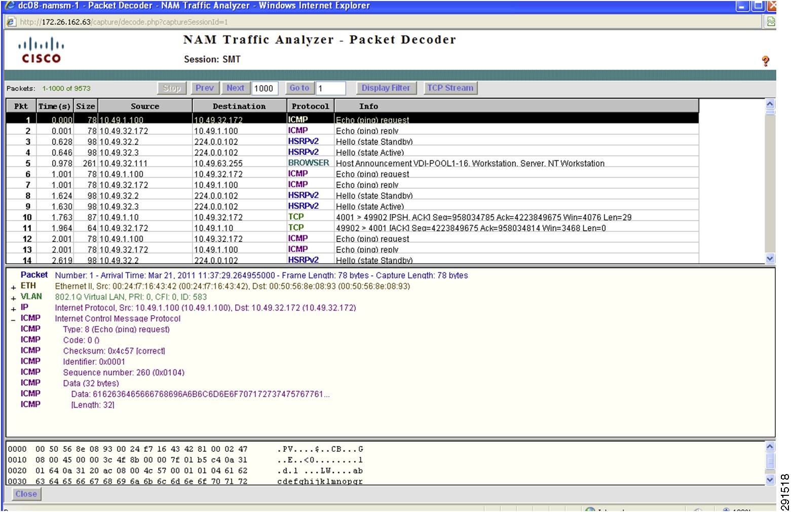
The Cisco Network Access Module (NAM) provides the capability to terminate Encapsulated Remote Switch Port Analyzer (ERSPAN) sessions and NetFlow connections. The Cisco Nexus 1000V can be configured to initiate ERSPAN sessions to the NAM, where the NAM can be used to capture packets and look at packet statistics. ERSPAN/NAM traffic flow is shown in Figure 13.
Figure 13 ERSPAN/NAM Traffic Flow
To configure ERSPAN between the Nexus 1000V and the services chassis:
1.
monitor session 1 type erspan-sourcedescription ** to NAM dc08-namsm-1 **source vlan 101-110 rxdestination ip 10.202.101.200erspan-id 1ip ttl 64ip prec 0ip dscp 0mtu 1500header-type 2monitor session 50 type erspan-sourcedescription ** INFRA to NAM dc08-namsm-1 **source vlan 590-600 rxdestination ip 10.202.101.200erspan-id 50ip ttl 64ip prec 0ip dscp 0mtu 1500header-type 22.
drs1-vsm1(config)# monitor session 50 type erspan-sourcedrs1-vsm1(config-erspan-src)# no shut3.
drs1-vsm1# sh monitorSession State Reason Description------- ----------- ---------------------- --------------------------------1 down Session admin shut ** to NAM dc08-namsm-1 **2 down Session admin shut ** to NAM dc07-namsm-1 **3 down Session admin shut ** to NAM dc08-namsm-1 **4 down Session admin shut ** to NAM dc07-namsm-1 **50 up The session is up ** INFRA to NAM dc08-namsm-1 **The following steps must be configured on the Catalyst 6500 for each ERSPAN session (only sessions 3, 4, and 50 are shown below):
monitor session 50 type erspan-destinationdescription ** N1k ERSPAN #50 - Tenant 50 INFRA **destination switch 1 analysis-module 9 data-port 2sourceerspan-id 50ip address 10.202.101.200monitor session 3 type erspan-destinationdescription ** N1k ERSPAN #1 - Tenanat 1 **destination switch 1 analysis-module 9 data-port 1sourceerspan-id 1ip address 10.202.101.200!!monitor session 4 type erspan-destinationdescription ** N1k ERSPAN #2 - Tenanat 2 **destination switch 2 analysis-module 9 data-port 1sourceerspan-id 2ip address 10.202.101.200Configuring the Cisco Virtual Network Access Module as a NetFlow Collector
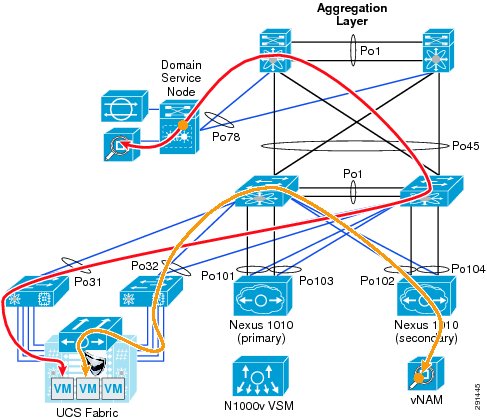
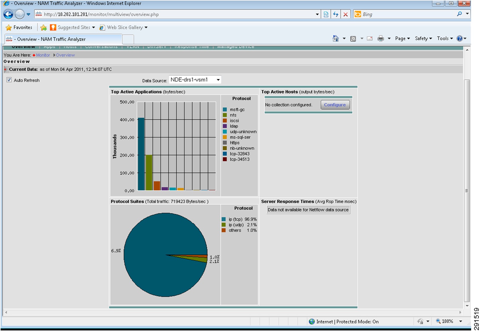
The Cisco Virtual Network Access Module (vNAM) is a virtual service blade on the Cisco Nexus 1010 that acts as a NetFlow collector. The traffic flow for the NAM and vNAM is shown in Figure 14.
Figure 14 NAM and vNAM Integration and Traffic Flow
You can use the vNAM as a NetFlow collector by performing the following steps:
1.
flow exporter vNAMdestination 10.202.101.201transport udp 3000source mgmt0version 9template data timeout 18002.
drs1-vsm1# show flow exporterflow monitor NFMonitorrecord netflow-originalexporter namsm-1exporter vNAMtimeout active 1800cache size 40963.
port-profile type vethernet Management_172_26_162vmware port-groupvmware max-ports 64switchport mode accessswitchport access vlan 162ip flow monitor NFMonitor inputip flow monitor NFMonitor outputservice-policy type qos input Gold_CoS_6no shutdownsystem vlan 162state enabledFlow exporter vNAM:
Destination: 10.202.101.201VRF: default (1)Destination UDP Port 3000Source Interface mgmt0 (172.26.163.109)Export Version 9Exporter StatisticsNumber of Flow Records Exported 50186128Number of Templates Exported 4313Number of Export Packets Sent 2239180Number of Export Bytes Sent 2262224948The following steps must be performed to configure vNAM:
smt-n1010-1(config)# virtual-service-blade NAMsmt-n1010-1(config-vsb-config)# enable primaryEnter vsb image: [nam-4-2-1.iso]Enter Management IPV4 address: 10.202.101.201Enter Management subnet mask: 255.255.255.0IPv4 address of the default gateway: 10.202.101.200Enter HostName: smt-1010-namSetting Web user/passwd will enable port 80. Enter[y|n]: [n] yWeb User name: [admin]Web User password: **********smt-n1010-1(config-vsb-config)# interface data vlan 902The configuration in the Cisco Nexus 1010 looks like this:
virtual-service-blade NAMvirtual-service-blade-type name NAM-1.0interface data vlan 902ramsize 2048disksize 53no shutdown secondaryDeploying Cisco Unified Computing System
The basic Cisco UCS configuration can be found in FlexPod for VMware Deployment Model (http://www.cisco.com/en/US/docs/solutions/Enterprise/Data_Center/Virtualization/flexpod_vmware.html). Details of the queuing and bandwidth control configuration used for ESMT are shown in Queuing and Bandwidth Control.
Queuing and Bandwidth Control
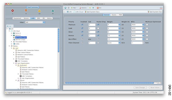
Queuing and bandwidth control are implemented within the Cisco UCS and at the access layer (Cisco Nexus 5000). Within the Cisco UCS, CoS values are assigned to a system class and given a certain percentage of the effective bandwidth. This is configured under the LAN tab in the Cisco UCS Manager (Figure 15).
Figure 15 Cisco UCS Manager—LAN Tab
The settings for the system classes are applied to traffic leaving the Cisco UCS 6100 fabric interconnects toward users and storage.
Deploying NetApp Storage
Deploying NetApp Data ONTAP
Each NetApp controller shares a unified storage architecture based on the Data ONTAP® 7G operating system and uses an integrated suite of application-aware manageability software. This provides an efficient consolidation of storage area network (SAN), network-attached storage (NAS), primary storage, and secondary storage on a single platform while allowing concurrent support for block and file protocols using Ethernet and Fibre Channel interfaces. These interfaces include Fibre Channel over Ethernet (FCoE), Network File System (NFS), Common Internet File System protocol (CIFS), and iSCSI. This common architecture allows businesses to start with an entry-level storage platform and easily migrate to the higher-end platforms as storage requirements increase, without learning a new OS, management tools, or provisioning processes.
To provide resilient system operation and high data availability, Data ONTAP 7G is tightly integrated into the hardware systems. The FAS systems use redundant, hot-swappable components. Combined with the patented dual-parity RAID-DP® (high-performance RAID 6), the net result can be superior data protection with little or no performance loss. For a higher level of data availability, Data ONTAP provides optional mirroring, backup, and disaster recovery solutions.
Active/Active Configuration
A NetApp active/active configuration keeps data available in the unlikely event of a controller failure or when controller maintenance might be necessary. Although this NetApp feature is highlighted in the "FlexPod for VMware Implementation Guide," it is important to understand some of the rules pertaining to a properly configured active/active controller pair and how the configuration can be tested to enable proper failover if an event should occur.
The Data ONTAP 7.3 Active/Active Configuration Guide details the complete rules and procedures that should be followed to keep the controller configuration consistent with proper active/active controller operation (https://now.netapp.com/NOW/knowledge/docs/ontap/rel7351/pdfs/ontap/aaconfig.pdf).
A component of NetApp Data Fabric® Manager (DFM), Operations Manager can be used to check the active/active configuration on both controllers in the high-availability (HA) pair. This tool provides a detailed list of items that are not in compliance with a proper active/active configuration as well as the actions that should be taken to correct such issues.
To run the active/active configuration check tool within Operations Manager:
1.
2.
3.
4.
5.
6.
7.
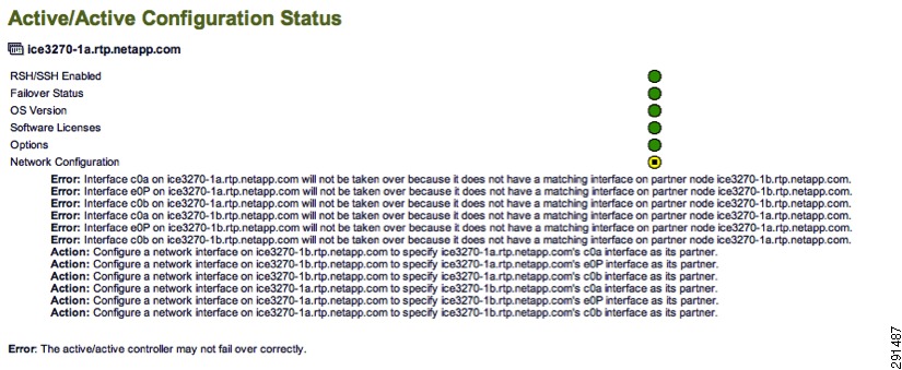
Several checks are performed during the active/active configuration check. Potential issues or configuration errors are presented in list format and appropriate actions should be taken to mitigate these items.
Figure 16 shows an active-active configuration status.
Figure 16 Active/Active Configuration Status
Active/Active Configuration Example
The following example details a proper active/active configuration as it pertains to the implementation of vFiler® units and their associated attributes. Note that other advanced settings are also either required or recommended to be identical on both controllers. The list of advanced settings can be found in the Data ONTAP 7.3 Active/Active Configuration Guide (https://now.netapp.com/NOW/knowledge/docs/ontap/rel7351/pdfs/ontap/aaconfig.pdf).
NetApp1> ifconfig -a<subsection of output>vif0: flags=0xa3d0a863<BROADCAST,RUNNING,MULTICAST,TCPCKSUM,VLAN> mtu 9000ether 02:a0:98:0b:b0:81 (Enabled virtual interface)vif0-106: flags=0x310a862<BROADCAST,RUNNING,MULTICAST,TCPCKSUM> mtu 9000partner vif0-106 (not in use)ether 02:a0:98:0b:b0:82 (Enabled virtual interface)vif0-109: flags=0x394a863<BROADCAST,RUNNING,MULTICAST,TCPCKSUM> mtu 9000partner vif0-109 (not in use)ether 02:a0:98:0b:b0:83 (Enabled virtual interface)vif0-110: flags=0x310a862<BROADCAST,RUNNING,MULTICAST,TCPCKSUM> mtu 9000partner vif0-110 (not in use)ether 02:a0:98:0b:b0:84 (Enabled virtual interface)vif0-115: flags=0x394a863<BROADCAST,RUNNING,MULTICAST,TCPCKSUM> mtu 9000partner vif0-115 (not in use)ether 02:a0:98:0b:b0:85 (Enabled virtual interface)vif0-119: flags=0x310a862<BROADCAST,RUNNING,MULTICAST,TCPCKSUM> mtu 9000partner vif0-119 (not in use)ether 02:a0:98:0b:b0:86 (Enabled virtual interface)vif0-120: flags=0x310a862<BROADCAST,RUNNING,MULTICAST,TCPCKSUM> mtu 9000partner vif0-120 (not in use)ether 02:a0:98:0b:b0:87 (Enabled virtual interface)vif0-124: flags=0x394a863<UP,BROADCAST,RUNNING,MULTICAST,TCPCKSUM> mtu 9000inet 10.3.102.100 netmask-or-prefix 0xffffff00 broadcast 10.3.102.255partner vif0-124 (not in use)ether 02:a0:98:0b:b0:88 (Enabled virtual interface)vif0-129: flags=0x394a863<UP,BROADCAST,RUNNING,MULTICAST,TCPCKSUM> mtu 9000inet 192.168.129.101 netmask-or-prefix 0xffffff00 broadcast 192.168.129.255partner vif0-129 (not in use)ether 02:a0:98:0b:b0:89 (Enabled virtual interface)vif0-130: flags=0x394a863<UP,BROADCAST,RUNNING,MULTICAST,TCPCKSUM> mtu 9000inet 192.168.130.100 netmask-or-prefix 0xffffff00 broadcast 192.168.130.255partner vif0-130 (not in use)ether 02:a0:98:0b:b0:8a (Enabled virtual interface)vif0-592: flags=0x394a863<UP,BROADCAST,RUNNING,MULTICAST,TCPCKSUM> mtu 9000inet 10.50.102.100 netmask-or-prefix 0xffffff00 broadcast 10.50.102.255partner vif0-592 (not in use)ether 02:a0:98:0b:b0:8b (Enabled virtual interface)vif0-599: flags=0x394a863<UP,BROADCAST,RUNNING,MULTICAST,TCPCKSUM> mtu 9000inet 192.168.99.101 netmask-or-prefix 0xffffff00 broadcast 192.168.99.255partner vif0-599 (not in use)ether 02:a0:98:0b:b0:8c (Enabled virtual interface)vif0-600: flags=0x394a863<UP,BROADCAST,RUNNING,MULTICAST,TCPCKSUM> mtu 9000inet 192.168.100.100 netmask-or-prefix 0xffffff00 broadcast 192.168.100.255partner vif0-600 (not in use)ether 02:a0:98:0b:b0:8d (Enabled virtual interface)</subsection of output>NetApp2> ifconfig -a<subsection of output>vif0: flags=0xa3d0a863<BROADCAST,RUNNING,MULTICAST,TCPCKSUM,VLAN> mtu 9000ether 02:a0:98:0b:b0:91 (Enabled virtual interface)vif0-106: flags=0x310a862<UP,BROADCAST,RUNNING,MULTICAST,TCPCKSUM> mtu 9000inet 10.1.102.100 netmask-or-prefix 0xffffff00 broadcast 10.1.102.255partner vif0-106 (not in use)ether 02:a0:98:0b:b0:92 (Enabled virtual interface)vif0-109: flags=0x394a863<UP,BROADCAST,RUNNING,MULTICAST,TCPCKSUM> mtu 9000inet 192.168.109.101 netmask-or-prefix 0xffffff00 broadcast 192.168.109.255partner vif0-109 (not in use)ether 02:a0:98:0b:b0:93 (Enabled virtual interface)vif0-110: flags=0x310a862<UP,BROADCAST,RUNNING,MULTICAST,TCPCKSUM> mtu 9000inet 192.168.110.100 netmask-or-prefix 0xffffff00 broadcast 192.168.110.255partner vif0-110 (not in use)ether 02:a0:98:0b:b0:94 (Enabled virtual interface)vif0-115: flags=0x394a863<UP,BROADCAST,RUNNING,MULTICAST,TCPCKSUM> mtu 9000inet 10.2.102.100 netmask-or-prefix 0xffffff00 broadcast 10.2.102.255partner vif0-115 (not in use)ether 02:a0:98:0b:b0:95 (Enabled virtual interface)vif0-119: flags=0x310a862<UP,BROADCAST,RUNNING,MULTICAST,TCPCKSUM> mtu 9000inet 192.168.119.101 netmask-or-prefix 0xffffff00 broadcast 192.168.119.255partner vif0-119 (not in use)ether 02:a0:98:0b:b0:96 (Enabled virtual interface)vif0-120: flags=0x310a862<UP,BROADCAST,RUNNING,MULTICAST,TCPCKSUM> mtu 9000inet 192.168.120.100 netmask-or-prefix 0xffffff00 broadcast 192.168.120.255partner vif0-120 (not in use)ether 02:a0:98:0b:b0:97 (Enabled virtual interface)vif0-124: flags=0x394a863<BROADCAST,RUNNING,MULTICAST,TCPCKSUM> mtu 9000partner vif0-124 (not in use)ether 02:a0:98:0b:b0:98 (Enabled virtual interface)vif0-129: flags=0x394a863<BROADCAST,RUNNING,MULTICAST,TCPCKSUM> mtu 9000partner vif0-129 (not in use)ether 02:a0:98:0b:b0:99 (Enabled virtual interface)vif0-130: flags=0x394a863<BROADCAST,RUNNING,MULTICAST,TCPCKSUM> mtu 9000partner vif0-130 (not in use)ether 02:a0:98:0b:b0:9a (Enabled virtual interface)vif0-592: flags=0x394a863<BROADCAST,RUNNING,MULTICAST,TCPCKSUM> mtu 9000partner vif0-592 (not in use)ether 02:a0:98:0b:b0:9b (Enabled virtual interface)vif0-599: flags=0x394a863<BROADCAST,RUNNING,MULTICAST,TCPCKSUM> mtu 9000partner vif0-599 (not in use)ether 02:a0:98:0b:b0:9c (Enabled virtual interface)vif0-600: flags=0x394a863<BROADCAST,RUNNING,MULTICAST,TCPCKSUM> mtu 9000partner vif0-600 (not in use)ether 02:a0:98:0b:b0:9d (Enabled virtual interface)</subsection of output>NetApp1> ipspace listNumber of ipspaces configured: 4default-ipspace (e0M e0P e0a e0b)Infrastructure_ipspace (vif0-592 vif0-599 vif0-600)SQL_ipspace (vif0-124 vif0-129 vif0-130)Exchange_ipspace (vif0-115 vif0-119 vif0-120)Sharepoint_ipspace (vif0-106 vif0-109 vif0-110)NetApp2> ipspace listNumber of ipspaces configured: 4default-ipspace (e0M e0P e0a e0b)Infrastructure_ipspace (vif0-592 vif0-599 vif0-600)SQL_ipspace (vif0-124 vif0-129 vif0-130)Exchange_ipspace (vif0-115 vif0-119 vif0-120)Sharepoint_ipspace (vif0-106 vif0-109 vif0-110)NetApp1> rdfile /etc/rc<subsection of output>vif create lacp vif0 -b ip e6a e6bvlan create vif0 106 110 119 120 124 130 583 589 590 592 600ifconfig vif0 partner vif0ifconfig e0a `hostname`-e0a netmask 255.255.0.0 mtusize 1500 mediatype auto flowcontrol full partner e0aifconfig vif0-106 `hostname`-vif0-106 netmask 255.255.255.0 mtusize 9000 partner vif0-106ifconfig vif0-109 `hostname`-vif0-109 netmask 255.255.255.0 mtusize 9000 partner vif0-109ifconfig vif0-110 `hostname`-vif0-110 netmask 255.255.255.0 mtusize 9000 partner vif0-110ifconfig vif0-115 `hostname`-vif0-115 netmask 255.255.255.0 mtusize 9000 partner vif0-115ifconfig vif0-119 `hostname`-vif0-119 netmask 255.255.255.0 mtusize 9000 partner vif0-119ifconfig vif0-120 `hostname`-vif0-120 netmask 255.255.255.0 mtusize 9000 partner vif0-120ifconfig vif0-124 `hostname`-vif0-124 netmask 255.255.255.0 mtusize 9000 partner vif0-124ifconfig vif0-129 `hostname`-vif0-129 netmask 255.255.255.0 mtusize 9000 partner vif0-129ifconfig vif0-130 `hostname`-vif0-130 netmask 255.255.255.0 mtusize 9000 partner vif0-130ifconfig vif0-592 `hostname`-vif0-592 netmask 255.255.255.0 mtusize 9000 partner vif0-592ifconfig vif0-599 `hostname`-vif0-599 netmask 255.255.255.0 mtusize 9000 partner vif0-599ifconfig vif0-600 `hostname`-vif0-600 netmask 255.255.255.0 mtusize 9000 partner vif0-600</subsection of output>NetApp2> rdfile /etc/rc<subsection of output>vif create lacp vif0 -b ip e6a e6bvlan create vif0 106 110 119 120 124 130 583 589 590 592 600ifconfig vif0 partner vif0ifconfig e0a `hostname`-e0a netmask 255.255.0.0 mtusize 1500 mediatype auto flowcontrol full partner e0aifconfig vif0-106 `hostname`-vif0-106 netmask 255.255.255.0 mtusize 9000 partner vif0-106ifconfig vif0-109 `hostname`-vif0-109 netmask 255.255.255.0 mtusize 9000 partner vif0-109ifconfig vif0-110 `hostname`-vif0-110 netmask 255.255.255.0 mtusize 9000 partner vif0-110ifconfig vif0-115 `hostname`-vif0-115 netmask 255.255.255.0 mtusize 9000 partner vif0-115ifconfig vif0-119 `hostname`-vif0-119 netmask 255.255.255.0 mtusize 9000 partner vif0-119ifconfig vif0-120 `hostname`-vif0-120 netmask 255.255.255.0 mtusize 9000 partner vif0-120ifconfig vif0-124 `hostname`-vif0-124 netmask 255.255.255.0 mtusize 9000 partner vif0-124ifconfig vif0-129 `hostname`-vif0-129 netmask 255.255.255.0 mtusize 9000 partner vif0-129ifconfig vif0-130 `hostname`-vif0-130 netmask 255.255.255.0 mtusize 9000 partner vif0-130ifconfig vif0-592 `hostname`-vif0-592 netmask 255.255.255.0 mtusize 9000 partner vif0-592ifconfig vif0-599 `hostname`-vif0-599 netmask 255.255.255.0 mtusize 9000 partner vif0-599ifconfig vif0-600 `hostname`-vif0-600 netmask 255.255.255.0 mtusize 9000 partner vif0-600</subsection of output>NetApp1> rdfile /etc/hosts<subsection of output>127.0.0.1 localhost# 0.0.0.0 NetApp1-vif0172.26.162.10 NetApp1 NetApp1-e0a# 0.0.0.0 NetApp1-e0b# 0.0.0.0 NetApp1-e0c# 0.0.0.0 NetApp1-e0d# 0.0.0.0 NetApp1-e0e# 0.0.0.0 NetApp1-e0f0.0.0.0 NetApp1-vif0-10610.1.102.100 NetApp2-vif0-1060.0.0.0 NetApp1-vif0-109192.168.109.101 NetApp2-vif0-1090.0.0.0 NetApp1-vif0-110192.168.110.100 NetApp2-vif0-1100.0.0.0 NetApp1-vif0-11510.2.102.100 NetApp2-vif0-1150.0.0.0 NetApp1-vif0-119192.168.119.101 NetApp2-vif0-1190.0.0.0 NetApp1-vif0-120192.168.120.100 NetApp2-vif0-1200.0.0.0 NetApp1-vif0-1240.0.0.0 NetApp2-vif0-124192.168.129.101 NetApp1-vif0-1290.0.0.0 NetApp2-vif0-129192.168.130.100 NetApp1-vif0-1300.0.0.0 NetApp2-vif0-13010.50.102.100 NetApp1-vif0-5920.0.0.0 NetApp2-vif0-592192.168.99.101 NetApp1-vif0-5990.0.0.0 NetApp2-vif0-599192.168.100.100 NetApp1-vif0-6000.0.0.0 NetApp2-vif0-600</subsection of output>NetApp2> rdfile /etc/hosts<subsection of output>127.0.0.1 localhost# 0.0.0.0 NetApp2-vif0172.26.162.11 NetApp2 NetApp2-e0a# 0.0.0.0 NetApp2-e0b# 0.0.0.0 NetApp2-e0c# 0.0.0.0 NetApp2-e0d# 0.0.0.0 NetApp2-e0e# 0.0.0.0 NetApp2-e0f0.0.0.0 NetApp1-vif0-10610.1.102.100 NetApp2-vif0-1060.0.0.0 NetApp1-vif0-109192.168.109.101 NetApp2-vif0-1090.0.0.0 NetApp1-vif0-110192.168.110.100 NetApp2-vif0-1100.0.0.0 NetApp1-vif0-11510.2.102.100 NetApp2-vif0-1150.0.0.0 NetApp1-vif0-119192.168.119.101 NetApp2-vif0-1190.0.0.0 NetApp1-vif0-120192.168.120.100 NetApp2-vif0-1200.0.0.0 NetApp1-vif0-1240.0.0.0 NetApp2-vif0-124192.168.129.101 NetApp1-vif0-1290.0.0.0 NetApp2-vif0-129192.168.130.100 NetApp1-vif0-1300.0.0.0 NetApp2-vif0-13010.50.102.100 NetApp1-vif0-5920.0.0.0 NetApp2-vif0-592192.168.99.101 NetApp1-vif0-5990.0.0.0 NetApp2-vif0-599192.168.100.100 NetApp1-vif0-6000.0.0.0 NetApp2-vif0-600</subsection of output>Security Hardening
NetApp recommends that you configure and enable an administrative user other than root immediately after initially setting up Data ONTAP. NetApp also recommends enabling secure protocols (refer to Table 3 for the default and recommended settings for each protocol) and disabling unsecure and unused protocols.
Data ONTAP has two distinct types of access: user data access through the NAS and SAN modules and administrative access through the storage controller's administrative module. Use caution when assigning elevated administrative access for any user. Data ONTAP has many security-related options that can be set to meet particular requirements. NetApp strongly recommends the use of secure administration methods for Data ONTAP and the disabling of any administrative protocols deemed to be of high risk. All management protocols used should be secure and encrypted whenever possible. For example, https should be used instead of http whenever possible.
Several services should be considered for disabling. Depending on the enterprise security structure, the state of any service depends on where the service is deployed and how deep it is in the infrastructure. The services in Table 3 do not require the purchase of additional licensing from NetApp. All of these settings are configurable through the options command within the Data ONTAP CLI.
For more information on securing NetApp storage controllers, refer to:
•
•
Centralized Logging
NetApp Data ONTAP has the ability to transmit logs to a centralized syslog server. The storage system receives information about the syslog server and what logs to send from the user configurable syslog.conf file. There are several pieces to Data ONTAP log messages including the "level" of logging and the "facility" of logging. The "level" of logging describes the severity of the message; the "facility" of logging describes the part of the system generating the message.
For further information on configuring centralized logging through the syslog.conf file, refer to the Data ONTAP 7.3 System Administration Guide. For Data ONTAP 7.3.5.1, which is configured in the current version of FlexPod for VMware, see: (https://now.netapp.com/NOW/knowledge/docs/ontap/rel7351/pdfs/ontap/sysadmin.pdf).
To enable logging:
1.
2.
The following is an example /etc/syslog.conf file:
NetApp> rd1file /etc/syslog.conf# $Id: //depot/prod/ontap/R7.3.3x/files/syslog.conf.sample#1 $# Copyright (c) 1994-1996 Network Appliance.# All rights reserved.# Sample syslog.conf file. Copy to /etc/syslog.conf to use.# You must use TABS for separators between fields.# Log messages of priority info or higher to the console and to /etc/messages*.info /dev/console*.info /etc/messages*.info @smt-splunk-1.smt.com# Edit and uncomment following line to log all messages of priority# err or higher and all kernel messages to a remote host, e.g. adminhost# *.err;kern.* @adminhost# Edit and uncomment following line to log all messages of priority# err or higher and all kernel messages to the local7 facility of the# syslogd on a remote host, e.g. adminhost.# *.err;kern.* local7.*@adminhost# Edit and uncomment following line to log all messages of priority# err or higher and all kernel messages to a remote host, e.g. adminhost,# at priority debug.# *.err;kern.* *.debug@adminhost# Edit and uncomment following line to log all messages of priority# err or higher and all kernel messages to the local5 facility of the# syslogd on a remote host, e.g. adminhost, at priority info.# *.err;kern.* local5.info@adminhostCentralized Authentication
NetApp Data ONTAP supports centralized authentication for both data access and storage controller administration. Supported centralized authentication and directory services include Microsoft Active Directory®, NIS, LDAP, and Kerberos. Microsoft Active Directory is the most commonly used and widely supported directory service and is therefore recommended in an ESMT environment.
Each physical or virtual (vFiler) storage controller can be added to the same Active Directory domain or added to separate independent Active Directory domains depending on the controller's purpose and owner (administrator or tenant). The procedure for joining a physical or virtual storage controller to an Active Directory domain is exactly the same and differs only in which context (physical or vFiler unit) the commands are executed.
For information on integrating NetApp storage into a Microsoft Active Directory domain as well as other directory services for both Windows and UNIX/Linux clients, see:
•
http://now.netapp.com/NOW/knowledge/docs/ontap/rel7351/pdfs/ontap/sysadmin.pdf•
http://now.netapp.com/NOW/knowledge/docs/ontap/rel7351/pdfs/ontap/filesag.pdf•
http://media.netapp.com/documents/tr-3771.pdf•
http://media.netapp.com/documents/tr-3458.pdf•
http://media.netapp.com/documents/tr-3457.pdf•
http://media.netapp.com/documents/tr-3464.pdfDeploying NetApp Operations Manager and Provisioning Manager
Security Hardening
Secure management interfaces should be used with NetApp Operations Manager and Provisioning Manager. Operations Manager is managed with a secure Web page (https on TCP port 8443). Provisioning Manager and Protection Manager are managed using the NetApp Management Console, which is a small client-based application installed on a management workstation. This workstation could also contain other management applications such as the VMware vSphere Client. Communication between the NetApp Management Console and Operations Manager also uses https on TCP port 8448. Both of these secure interfaces are enabled as part of the FlexPod for VMware deployment, along with disabling of the non-secure interfaces. Also, all communication between Operations Manager and Provisioning Manager and the NetApp storage systems should be secure. Storage system management should be setup with ssh (TCP port 22), https (TCP port 443), and snmpV3, which in this implementation encrypts the user login password. The vFiler units are managed with http (TCP port 80), but this management is all done within non-routed VLANs with private address spaces.
Centralized Logging
The Microsoft Windows version of NetApp Operations Manager and Provisioning Manager does not send logs to a centralized syslog server. These logs are stored locally on the server hosting Operations Manager. However, all actions initiated by NetApp Operations Manager and Provisioning Manager on the NetApp storage systems generate appropriately labeled storage system logs, which can be forwarded to a centralized syslog server.
Centralized Authentication
Since the versions of NetApp Operations Manager and Provisioning Manager included in FlexPod run on a Windows Server, centralized authentication can be set up in the Active Directory domain. RBAC can be used to provide appropriate capabilities to users on different resources within the environment.
Deploying NetApp Virtual Storage Console
NetApp Virtual Storage Console (VSC) is a VMware vCenterTM plug-in that provides four functions:
•
•
•
•
NetApp recommends installing VSC on a Windows Server 2008 R2 virtual machine along with NetApp Operations Manager and Provisioning Manager. On this virtual machine, in addition to the management network interface, network interfaces with jumbo frames setup should be configured in each storage network in the infrastructure for both infrastructure and tenant vFiler unit direct access. This direct access to the vFiler management interface is needed both to clone virtual machines and to back up virtual machines within a mounted datastore that is contained within a vFiler unit.
For more information on installing and configuring the NetApp VSC, see the NetApp Virtual Storage Console 2.1 for VMware vSphere Installation and Administration Guide (https://now.netapp.com/NOW/knowledge/docs/virtual_storage_console/relvsc21/pdfs/install.pdf).
Security Hardening
Secure interfaces should be used between NetApp VSC and VMware vCenter, for which VSC serves as a plug-in. In this case, a secure interface is the only option because both directions of communication between these two components occur using https on TCP port 443. Also, all communication between VSC and the NetApp storage systems should be secure. Storage system management should be set up with ssl (TCP port 443). vFilers are managed with http (tcp port 80), but this management is all done within non-routed VLANs with private address spaces.
Centralized Logging
VSC does not directly generate logs. However, all actions initiated by VSC on the NetApp storage systems generate appropriately labeled storage system logs that can be forwarded to a centralized syslog server. Additionally, all tasks utilizing the VSC vCenter Plug-in generate events and logs within vCenter.
Centralized Authentication
Since VSC runs on a Windows Server, centralized authentication can be set up in the Active Directory domain. Tasks performed by users using the VSC vCenter Server Plug-in are authenticated through vCenter.
Deploying NetApp SANscreen
Security Hardening
Because Netapp SANscreen® Server and Data Warehouse Server run on Microsoft Windows VMs, it is important to always follow Microsoft Windows security best practices whenever possible. This may include running the native Windows firewall or disabling any un-used protocols, and so on, to ensure the most secure environment possible. Microsoft provides a Security Compliance Toolkit to aid in the proper configuration of Microsoft Windows 2008 systems in the environment. Best practice documentation and guidelines can also be obtained for other operating system versions and platforms.
In order for NetApp SANscreen to work properly in a secure manner within the environment, it is important to create a specific SANscreen administrative user (that can be a cloud admin or storage admin) who possesses the capabilities to perform the necessary SANscreen operations and functions on the NetApp controllers. Once the SANscreen administrative user is created in Active Directory, the following procedure should be followed to provide the minimum capabilities to the user on each NetApp controller:
1.
Syntax:
useradmin role add <role_name> -a capability1[,capability2...]Example:
NetApp1> useradmin role add SANScreen_admin -a
api-*,login-http-admin,security-api-vfiler
Where:
–
–
–
2.
Syntax:
useradmin group modify <group_name> -r <custom_role>Example:
NetApp1> useradmin group modify SANScreen_admin_grp -r SANScreen_adminIn securing the SANscreen Server installation, it is also important to choose the correct secure protocols to use for communication to and from the local server. Always make sure to choose the secure protocol option, which, for example, might be using HTTPS versus HTTP. In this example, HTTPS is the preferred secure protocol. This methodology should apply to all aspects of the environment, not just the NetApp SANscreen Server configuration.
Centralized Authentication
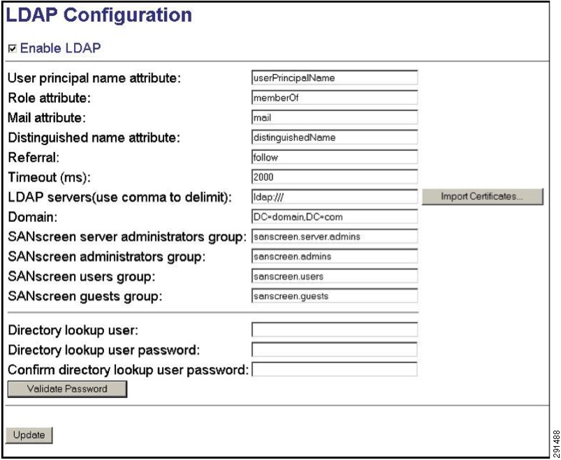
Outside of typical Windows Active Directory logon authentication, NetApp SANscreen Server leverages two methods for user authentication: LDAP version 2 or 3 and a local SANscreen user database. SANscreen first tries to authenticate the user against LDAP if LDAP has been enabled. Otherwise the user is authenticated against the local SANscreen user database. To enable LDAP:
1.
2.
3.
4.
Figure 17 shows the LDAP configuration screen.
Figure 17 LDAP Configuration
Deploying VMware
Installing and Configuring VMware vSphere
Installation and configuration procedures for VMware vSphere components (ESXi and vCenter Server) are identical to those documented in the FlexPOD deployment guide (NetApp Technical Report/TR-3892). The ESMT architecture runs on top of FlexPOD, therefore the standard procedures from FlexPOD deployment need to be completed.
After installation of vSphere, follow the steps below to configure the ESX clusters:
•
•
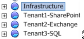
In the ESMT validation, option 2 was used. See Figure 18 for a reference of Cluster/Resource Pool layout for both management/infrastructure and individual tenants (Exchange, SQL, and SharePoint).
Figure 18 Cluster/Resource Pool Layout Example
1.
2.
3.
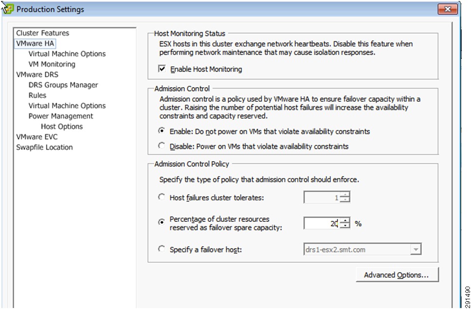
Note
Figure 19 HA Cluster Level Settings
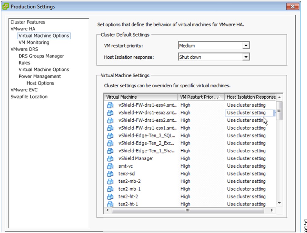
Note
Figure 20 VMware HA Virtual Machine Restart Priority
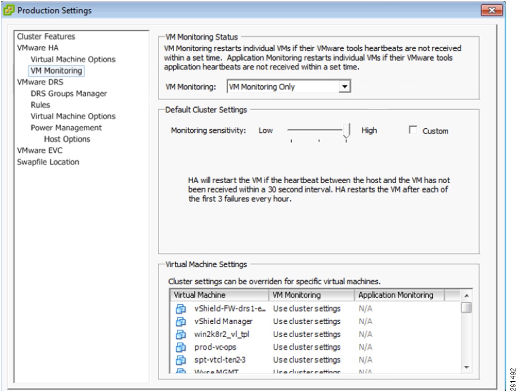
For VM monitoring, ensure cluster-wide setting is set to Enable, with threshold level set to High. Given that a large number of virtual machines in an ESMT environment are serving infrastructure management and production tenants, it is easier to set the cluster-wide setting to accommodate the most common setting. For individual non-production/less critical tenant virtual machines, the individual VM setting can override the cluster-level setting.
Figure 21 VMware HA VM Monitoring Sensitivity
Leave all VMware DRS and VMware EVC cluster-level settings at deafult.
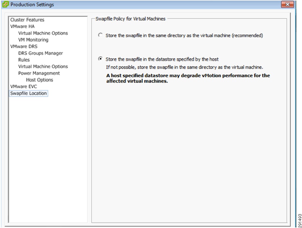
For Swapfile Location, ensure the swap file location is set to store in a specific datastore in the ESX host. This is the best practice recommendation when SRM is used for disaster recovery, as the dedicated datastore storing virtual machine swap file is not replicated.
Figure 22 Swapfile Location
Resource Pool settings for Infrastructure, Exchange, SQL, and SharePoint Tenants:
•
•
–
–
–
•
vCenter Server Secure Separation
With compute resources separated at the sub-resource pool level, vCenter Role Based Access Control (RBAC) needs to be configured to ensure end users have visibility into and control of their own resources.
The following steps are required to configure vCenter RBAC based on the Enhanced Secure Multi-Tenancy Design Guide recommendations (http://www.cisco.com/en/US/docs/solutions/Enterprise/Data_Center/Virtualization/securecldg_V2.html):
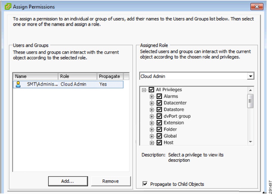
1.
Note
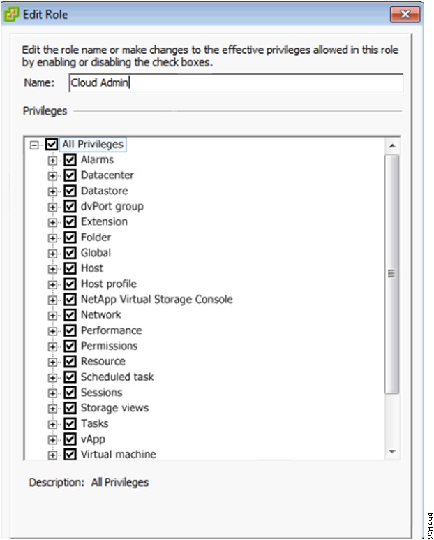
Figure 23 Cloud Admin Role—Access and Control to All Resources
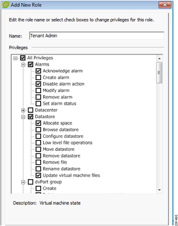
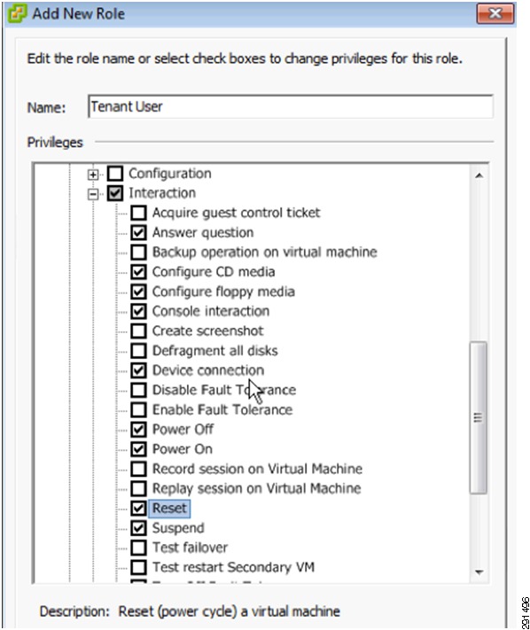
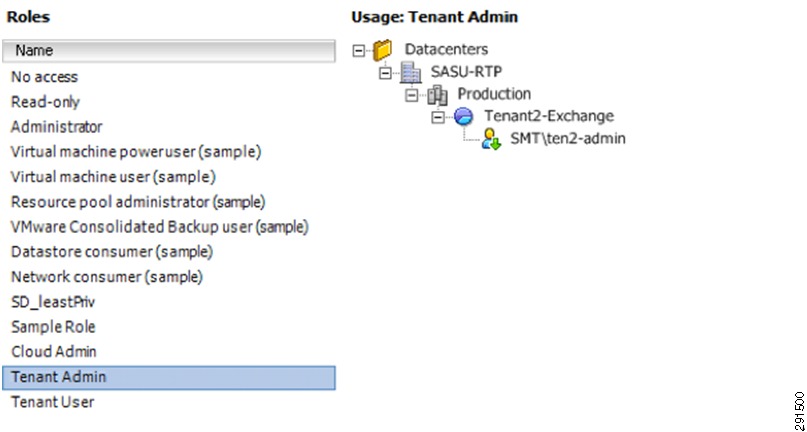
Tenant Admin has limited set of privileges compared to Cloud Admin and Tenant User has the most restrictive set of privileges (Figure 24 and Figure 25).
Figure 24 Tenant Admin Privileges
Figure 25 Tenant User Privileges
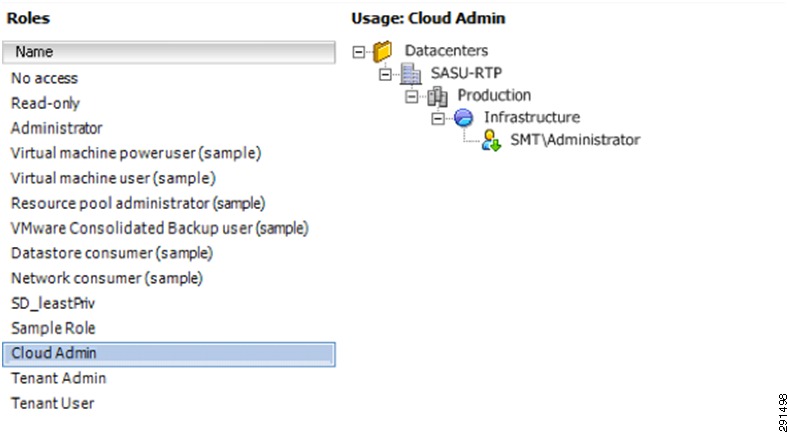
2.
Figure 26 Infrastructure Resource Pool Permission Assignment for Cloud Admin Role—Part 1
Figure 27 Infrastructure Resource Pool Permission Assignment for Cloud Admin Role—Part 2
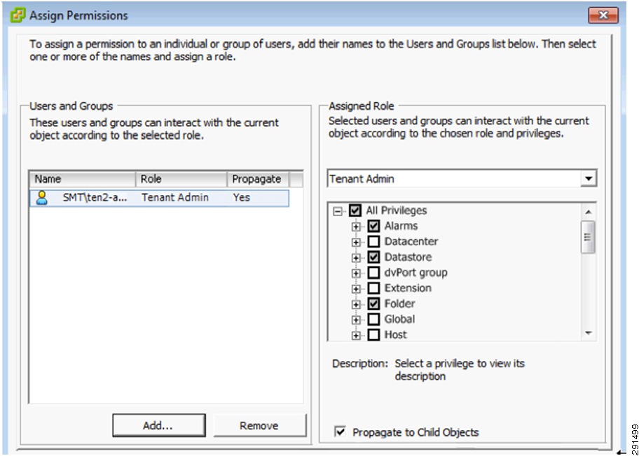
Figure 28 Tenant Resource Pool Permission Assignment for Tenant Admin Role—Part 1
Figure 29 Tenant Resource Pool Permission Assignment for Tenant Admin Role—Part 2
Follow similar steps for all tenants in the ESMT environment.
Installing and Configuring Additional VMware Components for ESMT
The following additional products are not in the base FlexPod and are required for ESMT:
•
•
vCenter Server Heartbeat (additional configuration steps with NetApp Virtual Storage Console):
•
•
In the ESMT deployment, option 2 is used. The NetApp VSC is installed on a separate virtual machine. No additional steps are needed for VSC to function in the event of vCenter Server failover (from primary to secondary).
If option 1 were used in the deployment, the following steps are required to ensure VSC is protected and functions correctly on failover of vCenter Server from primary to secondary.
Add Protection for Virtual Storage Console
Note
1.
2.
3.
4.
5.
Leave all service configurations to the default, "recover service".
6.
7.
8.
The vCenter Server Heartbeat now monitors and protects the NetApp Virtual Storage Console services and synchronizes the application data/configuration files so that both servers are able to fully function as vCenter Servers and NetApp Virtual Storage Console Servers. For additional information, refer to KB 1036507 (http://kb.vmware.com/kb/1036507).
vShield Configuration
Refer to Layer 2 Deployment for the steps needed to configure vShield for the protection of tenants.
Securing VMware vSphere ESXi
Security Hardening
•
a.
b.
c.
d.
e.
•
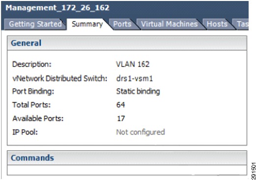
Figure 30 Management Network
•
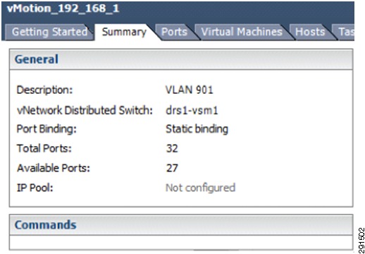
Figure 31 vMotion Network
•
Centralized Logging
For each ESXi host, follow the steps below to configure remote syslog:
1.
2.
3.
4.
Centralized Authentication
Given that the tenants are not granted access to ESXi server directly, no AD authentication is needed for the ESXi host.
Securing VMware vSphere vCenter Server
Security Hardening
•
•
To disable the datastore browser, edit the vpxd.cfg file and ensure that the following element is set:
<enableHttpDatastoreAccess>false</enableHttpDatastoreAccess>
This should be within the <vpxd>... </vpxd> element in the vpxd.cfg file.
Centralized Authentication
vCenter Server is part of the SMT domain, therefore users and groups defined in the central AD server can be used to access vCenter Server.
Securing VMware vShield
Security Hardening
•
To change the admin account password:
a.
b.
c.
d.
e.
f.
g.
h.
•
a.
b.
c.
d.
e.
f.
g.
•
Centralized Logging
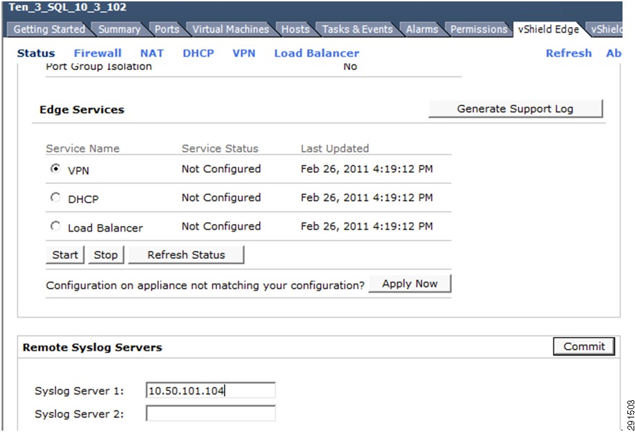
Configure remote syslog server for vShield Edge.
Figure 32 Centralized Logging Configuration for vShield Edge
Centralized Authentication
In the ESMT deployment, the Admin account is solely owned and controlled by the Cloud Admin. No access is given to the tenants.
Local Backup and Recovery
Local backup and recovery in an ESMT environment comes in the form of NetApp Snapshot copies. Whether the data being stored is a virtual machine C: drive or application binaries within a vmdk or application-specific data on raw device mappings (RDMs), all are initially backed up locally on the NetApp storage controller using NetApp Snapshot copies. Depending on the data type however, Snapshot copies are captured using different methods. For complete local virtual machine and application backups, several features are used together, including NetApp SnapDrive® and NetApp SnapManager® software.
Virtual Machine OS and Application Binaries
To capture Snapshot copies of virtual machines and application binaries (excluding application data on RDMs), NetApp SnapManager for Virtual Infrastructure (SMVI) is used. SMVI is now included as the Backup and Recovery tab within the NetApp Virtual Storage Console or VSC plug-in for VMware vCenter Server. Snapshot copies are triggered either by a user-configured schedule or manually within the SMVI GUI.
Figure 33 highlights hourly, daily, and weekly backup jobs created in the NetApp Backup and Recovery (SMVI) tab of VMware vCenter Server for the virtual machine named ten3_SQL that is stored in the NFS datastore named tenant_3_SQL_NFS_1.
Figure 33 Hourly, Daily, and Weekly Backup Jobs in NetApp Backup and Recovery Tab
For more information on installing and configuring SMVI as included in the NetApp VSC, see:
•
https://now.netapp.com/NOW/knowledge/docs/virtual_storage_console/relvsc21/pdfs/install.pdf•
https://now.netapp.com/NOW/knowledge/docs/virtual_storage_console/relvsc21/pdfs/backup.pdfApplication Specific Data
To capture Snapshot copies of application-specific data stored on VMware RDMs, the application-specific SnapManager software (for example, SnapManager for MS SQL) is used in conjunction with NetApp SnapDrive. NetApp SnapDrive is installed directly on the application server and allows for the creation, mapping, and management of block-level storage objects as they pertain to that instance of SnapDrive. SnapDrive communicates directly with both VMware vCenter Server and the NetApp storage controller (physical or virtual) to perform these functions as well as initiate Snapshot copies. NetApp SnapManager software is written by design to be application-specific in order to enable application consistent backups using NetApp Snapshot copies. NetApp SnapManager software collaborates with the application itself to prepare data in the file system for Snapshot capture. Once the application is prepared, NetApp SnapManager communicates with NetApp SnapDrive and initiates a Snapshot capture.
Use the Create Disk action within NetApp SnapDrive to add new RDM logical unit numbers (LUNs) to the virtual machine. NetApp SnapDrive follows this workflow to create new iSCSI attached RDM disks in an ESMT environment:
1.
2.
Note
3.
4.
5.
Figure 34 and Figure 35 highlight the iSCSI LUNs that have been created and mapped to the TEN3-SQL virtual machine using NetApp SnapDrive.
Figure 34 LUNs Mapped to Virtual Machine
Figure 35 Tenant 3 Storage View in Control Panel
For more information on installing and configuring NetApp SnapDrive, see the SnapDrive 6.3 for Windows; Installation and Administration Guide (https://now.netapp.com/NOW/knowledge/docs/snapdrive/relsnap631/pdfs/admin.pdf).
Once new RDMs have been added to the virtual machine leveraging SnapDrive, the appropriate NetApp SnapManager should be installed depending on the application. In this example, NetApp SnapManager for SQL is used. Once installed, SnapManager for SQL allows the migration of existing databases to the newly created and attached disks as well as the ability to create backup jobs within MS SQL for those databases. Once created, backup jobs are exported and available to the Microsoft SQL Server Management Studio under the SQL Server Agent Jobs folder. Figure 36 shows Tenant 3 backup options.
Figure 36 Tenant 3 Backup Options
In Figure 37, the backup jobs named Full_Backup and Transaction_Log_Backup have been created using NetApp SnapManager for SQL and automatically imported into the SQL Server Agent Jobs folder.
Figure 37 Backup Jobs Imported into the Jobs Folder
For more information on installing and configuring NetApp SnapManager products, see the application-appropriate SnapManager collateral on the NetApp Support (formerly NOW®) site (http://now.netapp.com/).
Disaster Recovery
SnapMirror Relationships
Once the appropriate data has been captured in NetApp Snapshots, the Snapshot copies can be replicated locally or to another data center for disaster recovery (DR) purposes. NetApp SnapMirror is a feature built into NetApp Data ONTAP that allows for the efficient replication or mirroring of data across two storage controllers. A baseline transfer is initially required to create a consistent mirror, but once the baseline is complete only data that has changed is transferred from that point forward.
The same software tools that were used to capture local Snapshot copies can also be used to initiate a SnapMirror update for disaster recovery purposes. When creating the local backup jobs using the Backup Wizards within both the NetApp VSC Backup and Recovery tab and NetApp SnapManagers, look for the appropriate checkbox to enable SnapMirror updates as an additional process to the backup workflow.
Note
Note
Figure 38 and Figure 39 show the checkboxes to enable SnapMirror update, first within the NetApp VSC Backup and Recovery Backup Wizard and second within the NetApp SnapManager for SQL Backup Wizard.
Figure 38 Enabling SnapMirror Update in NetApp VSC Backup and Recovery Backup Wizard
Figure 39 Enabling SnapMirror Update in NetApp SnapManaer for SQL Backup Wizard
VMware Site Recovery Manager (SRM)
VMware SRM works in conjunction with NetApp SnapMirror to provide an automated disaster recovery workflow if an unforeseen event should occur. VMware SRM server is installed at both the primary and the DR sites and communicates with the respective VMWare vCenter Servers at each location as well as the SnapMirror source and destination vFiler units. With the use of the NetApp Adapter for SRM, VMware SRM discovers existing SnapMirror relationships, the corresponding storage objects, and the virtual machines that are associated with these objects. These virtual machines are then added to protection groups within VMware SRM and protection workflows and priorities can be configured on an individual protection group basis depending on importance, etc. Once the protection groups are in place, failovers can be initiated from within the SRM portion of vCenter Server, which begins the configured disaster recovery plan(s). Test functionality is also built into SRM and the NetApp Adapter for SRM. This capability allows the administrator to test a failover scenario to ensure proper configuration without effecting the production VMs, applications, etc. Figure 40 provides an overview of disaster recovery.
Figure 40 Disaster Recovery Overview
The following documents provide more details on the installation and configuration of both NetApp SnapMirror and VMware Site Recovery manager in a DR scenario:
•
•
•
System Monitoring
System Monitoring Capabilities
Deploying a Centralized Syslog Server Monitoring
This architecture employs a hierarchical syslog monitoring system. Each tenant can be configured to have its own syslog server that only monitors events within a tenant. In turn each of the tenant's syslog servers forwards events to a centralized syslog repository, as shown in Figure 41.
Figure 41 Syslog Implementation within a Tenant
To deploy syslog servers:
1.
2.
Deploying Centralized Authentication and Access Monitoring
Active Directory and Cisco Access Control System (ACS) are the two major components that provide authentication capability within this architecture, as shown in Figure 42.
Figure 42 Implementing ACS within ESMT
Centralized authentication provides a unified approach that can reduce complexity and security concerns and provide operational efficiency. The following deployment framework was adapted in this architecture:
•
•
•
•
•
Table 4 outlines some of the user grouping and policy mapping between different categories of users and its associated assigned privileges.
Figure 43 shows the system-wide AD and hierarchy structure within the ESMT architecture.
Figure 43 Active Directory and Hierarchy Structure within ESMT
Deploying the Cisco Access Control System
In this deployment Active Directory is used to define the different groups of users, while ACS is used to give each group a scope of permissions within the cloud. All the devices that will be using ACS must be entered as a network device. Like devices are grouped together for ease of administration.
Figure 44 ACS Network Device Entry
The AD instance is used as an identity store in ACS. Once linked, ACS uses the AD user list to determine if the user is valid.
Figure 45 ACS Active Directory Identity Store Entry
Use Shell Profiles in ACS to define the different scopes of permissions on the different devices (for example, network operator access on Cisco Nexus devices, privilege level 15 on IOS boxes, and so on).
Figure 46 Shell Profile Definition
Once these elements are configured, they can be used to build access policies in ACS.
Figure 47 Access Policy for Default Network Administration
As users log in to devices, they are put in the appropriate groups according to the AD implementation and given the appropriate permissions according to the ACS configuration.
For more information on configuring ACS, see: http://www.cisco.com/en/US/docs/net_mgmt/cisco_secure_access_control_system/5.2/user/guide/acsuserguide.html.
Monitoring Capability with Network Access Module
Once the NAM is configured, the following steps enable one to monitor traffic using the NAM user interface.
1.
Figure 48 NAM Capture Session
2.
Figure 49 Starting Capture
3.
Figure 50 Packet Decoder
Monitoring Capability with the Cisco Virtual Network Access Module
Once vNAM is configured, one can connect to the vNAM, using the vNAM address, with a Web interface. Using the Web interface one can choose the profile (NDE-drs1-vsm) from the Monitor/Overview pane and view the traffic flow from the Cisco Nexus 1010, as shown in Figure 51.
Figure 51 Monitoring Traffic Using vNAM
Monitoring Traffic Flow through Physical Firewall
The ASDM tool for Cisco firewalls is used to monitor both inside and outside interface traffic. Firewall rules, ARP tables, and NAT rules within all contexts can be viewed using the ASDM monitoring capability. The SharePoint tenant, with multiple users accessing a variety of services within the SharePoint environment, is shown in Figure 52.
Figure 52 Monitoring Traffic Using ASDM Monitoring Tool
Monitoring Capability of ACE Load Balancer
The Cisco Application Network Manager (ANM) displays statistics, such as concurrent connections, connections per second, etc., for the ACE load balancer. These statistics can be monitored and graphed in real time for each physical server, as shown in Figure 53.
Figure 53 Monitoring ACE Using ANM
The various health-probes can also be monitored using the ANM, as shown in Figure 54.
Figure 54 Monitoring Health Probes Using ANM
Cisco Intrusion Prevention System Monitoring and Mitigation
The IPS can monitor and mitigate a variety of attacks, such as worms, Trojans, etc. Either the Cisco IPS Manager Express (IME) or Cisco Security Manager (4.2) can be used for monitoring. The IME can import the IPS devices and monitor the health of the network.
The following steps can be taken to mitigate attacks using the Cisco IPS:
1.
2.
3.
4.
5.
6.
Figure 55 IPS Event Monitoring View
Monitoring Capability Within vShield
vShield can monitor realtime traffic and discover VMs.
Monitoring Realtime Traffic
Monitoring realtime traffic can be important. In the event of a attack, it is necessary to be determine the realtime traffic profile and characteristics to mitigate the attack. Within the VM flow tab, Show Report provides a realtime view of the traffic, as shown in Figure 56. Most malicious attacks are visible through the uncategorized traffic, as the port numbers are random and categorized traffic shows the predefined port-mappings as defined in the port-mapping table under VM flow.
Figure 56 Monitoring Real-time Traffic
Figure 57 shows a graphical representation of traffic that is pre-defined in the port-mapping configuration table, as shown in Figure 57.
Figure 57 VM Chart
VM Discovery
VM Discovery enables one to monitor inter-tenant and intra-tenant steady-state available services. This can be useful in cases where one wants to ascertain which ports are visible and active for a particular VM. One can start the VM discovery process by operating on each vShield agent and staring the VM discovery process. One can perform this discovery continuously or in a scheduled manner, as shown in Figure 58.
Figure 58 Scheduling VM Discovery
Once the VM discovery process is complete, one can view the steady state traffic and open ports, as shown in Figure 59.
Figure 59 VM Discovery Mode
VM discovery only works with tenants that are routable to the management VLAN.
Load Balancing
100 separate users accessed the SharePoint servers concurrently (this was done using the Microsoft Visual Studio tool). The 100 concurrent connections were between two real servers. The ACE was able to load balance these many concurrent connections, as shown in Figure 60.
Figure 60 Monitoring Conncurrent Load Balancing Sessions
Deploying Tenant Resources and Security
Tenant Storage Resources
Tenant vFiler Units
NetApp Operations Manager and Provisioning Manager should be used to provision tenant vFiler units and to apply consistent storage efficiency policies to storage within those vFiler units. To provision tenant vFiler units, a tenant storage VLAN with an MTU of 9000—if jumbo frames are being used—must be provisioned in the Cisco Nexus 1000V, in the Cisco UCS fabric and all Cisco UCS vNICs on the ESXi hosts, in the Cisco Nexus 5000s, and on the storage system VIF. Tenant datastores should be provisioned with the Virtual Storage Console (VSC) Provisioning and Cloning Utility, as described in the following section. Tenant storage policies should be created for both NFS and SAN (iSCSI) storage. Storage can then be consistently provisioned using these policies. Storage provisioned with VSC can also be imported into datasets that include the policies in order to apply the policies to that storage.
Tenant NFS Datastores
NetApp recommendeds provisioning tenant NFS datastores using the VSC Provisioning and Cloning Utility. To provisionin tenant NFS datastores in this way, a tenant storage VLAN with an MTU of 9000—if jumbo frames are being used—must be provisioned in the Cisco Nexus 1000V, in the Cisco UCS fabric and all Cisco UCS vNICs on the ESXi hosts, in the Cisco Nexus 5000s, and on the storage system VIF. The tenant vFiler unit should be provisioned using NetApp Provisioning Manager and should include the VLAN just created. Also, a VMware vmkernel port must be provisioned on each ESXi host from which you want to mount the datastore. This vmkernel port should be provisioned with an MTU of 9000 if jumbo frames are being used. In order to create a vmkernel port with an MTU of 9000, first provision the port on the Cisco Nexus 1000V in vCenter under the ESXi host Configuration tab where Networking, then vNetwork Distributed Switch, then Manage Virtual Adapters is selected. This creates a vmkernel port with an MTU of 1500. It is then necessary to log into the ESXi host console, query and delete the port, then add it back in to the DVS on the same DVS port with an MTU of 9000. This vFiler unit then must be added as a storage system on the VSC Provisioning and Cloning Storage controllers screen.
Once the network, the vmkernel port, and the tenant vFiler unit have been properly setup, the new tenant NFS datastore can be setup by selecting NetApp in the right-click menu on the cluster containing all the ESXi hosts where the datastore is to be mounted. The storage system containing the vFiler unit should be selected along with the vFiler context. Once Finish is selected, VSC creates the volume for the datastore on the storage system, moves the volume into the tenant vFiler unit, creates the NFS exports to all of the ESXi hosts in the cluster, and mounts the datastore on all ESXi hosts in the cluster. The VSC Provisioning and Cloning Utility can then be used to clone VMs within this new datastore. The VSC Backup and Recovery Utility can also be used to take consistent Snapshot copies of the VMs in this datastore. The datastore volume can also be imported into a dataset in Provisioning Manager to automatically apply storage efficiency policies to the volume, such as Deduplication Management.
Intra- and Inter-Tenant Traffic Rules
This section outlines the necessary steps to achieve network isolation between and within tenants.
Deploying vShield—Implementing Security Rules at the Access Layer
A virtual firewall such as VMware's vShield can be used to create separation between tenants and from outside. Within the access layer in the ESMT architecture, virtual firewalls are implemented to segment traffic within the same tenant environment (sometimes referred to as east-west traffic, or optionally across tenants as well). Figure 61 shows how the various traffic flows are protected by virtual and physical firewalls.
Figure 61 Traffic Flows within a Multi-Tenant Architecture
Firewall rules can be easily set to deny or authorize hosts based on an IP address or specific VLANs. It can also lock down traffic to certain ports. The example below shows how the SharePoint tenant is allowed access only from the branch (10.1.151.x subnet).
For example:
1.
Figure 62 Host & Clusters View
2.
Figure 63 Data Center View
3.
Figure 64 App Firewall Pane
4.
Figure 65 Branch-Tenant 1 Firewall Rules
5.
Figure 66 Firewall Rules Restricting Traffic to Tenant 1
6.
Figure 67 Root Cluster View
7.
Figure 68 L2/L3 Rules in the App Firewall Pane
8.
Figure 69 L2/L3 Firewall Rule for Tenant 1
Configuring NAT Between SharePoint and Infrastructure Tenant
The SharePoint tenant needs access to the shared Infrastructurre tenant for Active Directory and other services. To perform this, vShield edge can be deployed to provide NAT between SharePoint and AD tenants, as shown below. The back-end subnet 10.1.102.X is NATed to the Infrastructurre tenant.
1.
Figure 70 vShield Edge View
2.
–
–
3.
Figure 71 vShield Edge Configuration Pane
4.
Figure 72 NAT Configuration Pane
5.
Configuring Rules in the Backend to Securely Deploy Database Applications
Optionally one can use the vShield to create rules between different hosts in the same tenant. There may be a case where the different database components coexist with other virtual machines in the same tenant. The vApp feature within vShield lets you set rules based on host IP address within the same tenant. In Figure 73, the ten1-media1 server (IP address 10.1.101.106) is only accessed from outside and is denied access to all hosts within the SharePoint infrastructure.
1.
2.
Figure 73 vApp Firewall Rules within Tenant 1
3.
Figure 74 vApp L2/L3 Firewall Example
Deploying the Cisco Firewall Switching Module—Implementing Security Rules at Services Layer
Optionally the firewall at the services layer can be configured to isolate tenants from outside or from each other. The choice is up to the network administrator, where he/she may decide to isolate high-performance tenants using a physical firewall at the services layer. In the example below the exchange tenant is isolated from other tenants and outside traffic is restricted to a predefined subnet (10.2.51.0). One can use the ASDM configuration tool to perform this task:
1.
2.
Figure 75 Configuring Firewall Rules with FWSM
3.
Figure 76 FWSM Firewall Rule Configuration Window
Attack Mitigation
A specific attack was initiated from outside the network and seen on the main dashboard.
Figure 77 IPS Dashboard Events View
The Signature ID was used to locate the attack within the available list of signatures and appropriate actions were taken by right clicking the signature to drop these packets and mitigate the attack, as shown in Figure 78.
Figure 78 Configuring Actions to Mitigate Attacks
One could also go to the Event Monitoring/Dropped View screen to view dropped packets in real time or from a previous time span.
Figure 79 Dropped Attacks Event Statistics
Figure 80 shows the detection of an ICMP sweep by IPS. Event views in the Event Monitoring pane show that IPS detected the ICMP sweep in realtime.
Figure 80 Detecting ICMP Sweep
vShield could also be used to mitigate suspicious traffic. The Flow Monitoring pane displays the various traffic flows for each VLAN. In Figure 81, traffic flows for the tena2-cas1 VM are shown.
Figure 81 Monitoring Specific Flow Statistics with vShield
If one of the traffic flows is deemed to be suspicious, one can create a rule automatically by clicking the flow in the Firewall column. This takes the user to the App Firewall pane with the rule automatically created, as shown in Figure 82 for a traffic flow with destination port 45421.
Figure 82 Configuration Window to Stop Malicious Traffic
Appendix A—PCI Compliance
The Payment Card Industry Data Security Standard (PCI-DSS) defines a set of requirements for the configuration, operation, and security of payment card transactions in your business. If you use ESMT to store, process, or transmit payment card information, these standards and this guide apply to you.
Failure to comply with these standards can result in significant fines should a security breach occur. For more details about PCI DSS, see: https://www.pcisecuritystandards.org/security_standards/pci_dss.shtml.
Summary of PCI DSS Requirements
The following summary provides a basic overview of the PCI DSS requirements and shows how they apply to your business and to the ESMT architecture.
Requirement 1—Install and Maintain a Firewall Configuration to Protect Cardholder Environment
What the Requirement Says:
Firewalls are devices that control computer traffic allowed between an entity's networks (internal) and untrusted networks (external), as well as traffic into and out of more sensitive areas within an entity's internal trusted networks. The cardholder data environment is an example of a more sensitive area within an entity's trusted network.
A firewall examines all network traffic and blocks those transmissions that do not meet the specified security criteria.
All systems must be protected from unauthorized access from untrusted networks, whether entering the system through the Internet as e-commerce, employee Internet access through desktop browsers, employee e-mail access, dedicated connections such as business-to-business connections, through wireless networks, or through other sources. Often, seemingly insignificant paths to and from untrusted networks can provide unprotected pathways into key systems. Firewalls are a key protection mechanism for any computer network.
Other system components may provide firewall functionality, provided they meet the minimum requirements for firewalls as provided in Requirement 1. When other system components are used within the cardholder data environment to provide firewall functionality, these devices must be included within the scope and assessment of Requirement 1.
How the ESMT Architecture and Components Meet These Requirements:
The ESMT architecture includes the ability to completely segment systems, not only between but also within tenants. At the physical layer, physical firewall appliances or modules provide the functionality to segment different tenants. In addition, these firewalls provide a strong line of defense against outside attacks on the data center infrastructure and unauthorized access to cardholder data. Within the access layer in the ESMT architecture, virtual firewalls are implemented to segment traffic within the same tenant environment (sometimes referred to as east-west traffic, or optionally across tenants as well). Figure 61 in Deploying vShield—Implementing Security Rules at the Access Layer (shown in Figure 83 for reference) shows how the various traffic flows are protected by virtual and physical firewalls.
Figure 83 Traffic Flows within a Multi-Tenant Architecture
Firewall rules can easily be set to deny or authorize hosts based on IP address or specific VLANS. The firewall can also lock down traffic to certain ports, as shown in Deploying vShield—Implementing Security Rules at the Access Layer.
Example:
In Figure 83, the Tenant 1 environment is composed of the Common Desktop Environment (CDE, also known as Payment Card Industry [PCI] environment), while the Tenant 2 environment is composed of another tenant that the client wants to completely segment from the CDE. The client also wants to allow only certain connections from the branch environment into the PCI zone.
This PCI environment (Tenant 1) is composed of the following systems:
•
•
•
The Tenant 2 environment is composed of the:
•
One method to secure the CDE from threats from outside is to grant access only to predefined hosts and to lock down traffic to certain ports. To accomplish this, follow the procedure in Deploying vShield—Implementing Security Rules at the Access Layer.
Requirement 2—Do Not Use Vendor-Supplied Defaults for System Passwords and other Security Parameters
What the Requirement Says:
Malicious individuals (external and internal to an entity) often use vendor default passwords and other vendor default settings to compromise systems. These passwords and settings are well known by hacker communities and are easily determined through public information.
How the ESMT Architecture and Components Meet these Requirements:
The Cisco ESMT architecture is composed of many different foundational components. In order to change vendor supplied defaults and harden systems in accordance with security best practices follow the links referred to below.
Note
•
–
–
•
–
–
•
–
–
•
•
https://now.netapp.com/NOW/knowledge/docs/ontap/rel7351/pdfs/ontap/sysadmin.pdf
•
–
http://www.vmware.com/pdf/vsz_10_admin.pdf
•
–
–
•
–
•
http://www.cisco.com/en/US/docs/switches/lan/catalyst6500/ios/12.2SX/configuration/guide/swcgIX.html
•
http://www.cisco.com/en/US/docs/ios/sec_user_services/configuration/guide/sec_cfg_sec_4cl.html
Wireless is not a part of the proposed architecture, but could be if the client needs it. In this case, the client is responsible for ensuring that the wireless network is using strong authentication/encryption protocols (e.g., WPA, WPA2) and that only services that are needed are allowed into the CDE environment. Steps provided in requirement 1 would be used to segment any wireless network from the rest of the CDE environment.
Requirement 3—Protect Stored Cardholder Data
What the Requirement Says:
Protection methods such as encryption, truncation, masking, and hashing are critical components of cardholder data protection. If an intruder circumvents other security controls and gains access to encrypted data, without the proper cryptographic keys, the data is unreadable and unusable to that person. Other effective methods of protecting stored data should be considered as potential risk mitigation opportunities. For example, methods for minimizing risk include not storing cardholder data unless absolutely necessary, truncating cardholder data if full PAN is not needed, and not sending unprotected PANs using end user messaging technologies, such as e-mail and instant messaging.
How the ESMT Architecture and Components Meet these Requirements:
Requirement 3 is the responsibility of the client. The Cisco ESMT architecture does not interfere with the client's ability to securely store cardholder data. The client has the option to encrypt data before it is stored. The network connectivity between the application and storage is segmented and inaccessible to unauthorized users. All key handling and management procedures outlined in Requirement 3 are the sole responsibility of the client.
Requirement 4—Encrypt Transmission of Cardholder Data Across Open, Public Networks
What the Requirement Says:
Sensitive information must be encrypted during transmission over networks that are easily accessed by malicious individuals. Misconfigured wireless networks and vulnerabilities in legacy encryption and authentication protocols continue to be targets of malicious individuals who exploit these vulnerabilities to gain privileged access to cardholder data environments.
How the ESMT Architecture and Components Meet these Requirements:
Requirement 4 is the responsibility of the client. The Cisco ESMT architecture does not prohibit the client's ability to securely transmit cardholder information over public networks. The client has the option of using IPsec, SSL, or another secure method to provide secure connectivity over public networks. IPsec tunnels can be safely terminated within the corporate network or VPN technologies can provide data integrity over a public infrastructure. In either case cardholder transactions over public networks can be encrypted in accordance with PCI. For more details on how to implement IPsec and SSL termination, see the references below.
The links to implement encryption over the public network are:
•
•
Requirement 5—Use and Regularly Update Anti-Virus Programs
What the Requirement Says:
Malicious software, commonly referred to as malware—including viruses, worms, and Trojans—enters the network during many business-approved activities including employee e-mail and use of the Internet, mobile computers, and storage devices, resulting in the exploitation of system vulnerabilities. Anti-virus software must be used on all systems commonly affected by malware to protect systems from current and evolving malicious software threats.
How the ESMT Architecture and Components Meet These Requirements:
Requirement 5 is the responsibility of the client. The Cisco ESMT architecture does not interfere with the client's ability to regularly update anti-virus software on the systems they deploy in this environment.
Note
Requirement 6—Develop and Maintain Secure Systems and Applications
What the Requirement Says:
Unscrupulous individuals use security vulnerabilities to gain privileged access to systems. Many of these vulnerabilities are fixed by vendor-provided security patches, which must be installed by the entities that manage the systems. All critical systems must have the most recently released, appropriate software patches to protect against exploitation and compromise of cardholder data by malicious individuals and malicious software.
How the ESMT Architecture and Components Meet These Requirements:
The client has the ability to use VMware update manager (VUM) for updating and patching Vcenter system software and guest OS operating systems. The steps can be found at: http://www.vmware.com/pdf/vi3_vum_10_admin_guide.pdf
Any guest operating system that is not supported by VUM must be patched either by another automated means (WSUS, commercial product, etc.) or manually. The Cisco ESMT architecture can be configured to allow for VM s to access a repository of updated images and patches. Network devices can be updated by using secure TFTP/FTP server within the ESMT environment. Relevant inks are provided below.
•
–
•
–
http://www.cisco.com/en/US/docs/switches/datacenter/sw/4_1/nx-os/upgrade/guide/nx-os_upgrade.html
•
–
•
–
http://www.vmware.com/pdf/vsz_10_admin.pdf
•
–
•
–
http://www.cisco.com/en/US/docs/security/ips/7.0/configuration/guide/cli/cli_system_images.html
•
–
Note
Requirement 7—Restrict Access to Cardholder Data by Business Need to Know
What the Requirement Says:
To limit access to critical data to authorized personnel only, systems and processes must be in place to limit access based on need to know and according to job responsibilities.
How the ESMT Architecture and Components Meet These Requirements:
Requirement 7 is the responsibility of the client. The Cisco ESMT architecture does not interfere with allowing only those individuals who require such access into the CDE. Cisco Secure Access Control Server (ACS) and Windows Active Directory provide excellent capabilities to log and document any user who accesses devices within the CDE, whether it is VMware's virtual software components or networking and storage devices. the ESMT architecture allows secure connectivity between these devices and ACS/AD servers. Group policies can be created within ACS and AD configurations that can also restrict user access privileges based on the individual's user ID. In addition, group attributes, as well as incorporating tenant-id and global-id or for tenant and cloud system administrators, can be used.
Note
Requirement 8—Assign a Unique ID to Each Person with Computer Access
What the Requirement Says:
Assigning a unique identification (ID) to each person with access makes each individual uniquely accountable for his or her actions. When such accountability is in place, actions taken on critical data and systems are performed by, and can be traced to, known and authorized users.
How the ESMT Architecture and Components Meet These Requirements:
Requirement 8 is the responsibility of the client. The client must ensure that all operating systems, applications, and network devices attached to the PCI network are accessed using unique IDs. For Cisco-specific network devices, see Requirement 2 for links to manuals explaining how to assign unique user IDs. All passwords should meet the following requirements:
•
•
•
•
•
•
•
•
•
•
•
Note
Requirement 9—Restrict Physical Access to Cardholder Data
What the Requirement Says:
Any physical access to data or systems that house cardholder data provides the opportunity for individuals to access devices or data and to remove systems or hardcopies and should be appropriately restricted. For the purposes of Requirement 9, "onsite personnel" refers to full-time and part-time employees, temporary employees, contractors, and consultants who are physically present on the entity's premises. A "visitor" refers to a vendor, guest of any onsite personnel, service workers, or anyone who needs to enter the facility for a short duration, usually not more than one day. "Media" refers to all paper and electronic media containing cardholder data.
How the ESMT Architecture and Components Meet These Requirements:
Requirement 9 is the responsibility of the client. The Cisco ESMT architecture does not interfere with where the client chooses to implement this solution and how media backups are performed and handled.
Requirement 10—Track and Monitor All Access to Network Resources and Cardholder Data
What the Requirement Says:
Logging mechanisms and the ability to track user activities are critical in preventing, detecting, or minimizing the impact of a data compromise. The presence of logs in all environments allows thorough tracking, alerting, and analysis when something does go wrong. Determining the cause of a compromise is very difficult, if not impossible, without system activity logs.
How the ESMT Architecture and Components Meet These Requirements:
All Cisco device events are forwarded to a syslog server for logging purposes. These logs must be stored for a year based on PCI-DSS requirements. The ESMT architecture incorporates a tiered syslog solution in which each tenant incorporates its own syslog server and events from all tenants are forwarded to a central syslog repository server. For details on implementing syslog servers, see this general link for guidance on configuring syslog on Cisco networking devices: http://www.cisco.com/en/US/docs/solutions/Enterprise/Security/Baseline_Security/securebasebook.html.
Requirement 11—Regularly Test Security Systems and Processes
What the Requirement Says:
Vulnerabilities are being discovered continually by malicious individuals and researchers and being introduced by new software. System components, processes, and custom software should be tested frequently to ensure security controls continue to reflect a changing environment.
How the ESMT Architecture and Components Meet These Requirements:
Requirement 11 of the PCI DSS is the responsibility of the client. The Cisco ESMT architecture does not interfere with the client's ability to regularly test CDE systems. ESMT architecture incorporates the use of Cisco Intrusion Prevention systems (IPS) which provides the capability of detecting Denial of Service (DOS) attacks and attacks in the form of malware, worms, and Trojans. Figure 84 is a screenshot for the Cisco IPS interface.
Figure 84 Cisco IPS Interface
For the steps that can be taken to mitigate attacks using the Cisco IPS, see Cisco Intrusion Prevention System Monitoring and Mitigation.
Requirement 12—Maintain a Policy that Addresses Information Security for All Personnel
What the Requirement Says:
A strong security policy sets the security tone for the whole entity and informs personnel about what is expected of them. All personnel should be aware of the sensitivity of data and their responsibilities for protecting it. For the purposes of Requirement 12, "personnel" refers to full-time and part-time employees, temporary employees, contractors, and consultants who are resident on the entity's site or otherwise have access to the cardholder data environment.
How the ESMT Architecture and Components Meet These Requirements:
Requirement 12 is the responsibility of the client. All policies and procedures with regards to PCI should be created and disseminated by the client.
Appendix B—ICSA Labs
ICSA Labs is an independent auditor that has been providing credible, independent, third-party product assurance for end users and enterprises for the last 20 years. ICSA Labs was invited to perform an audit of SMT built on FlexPod for VMware on behalf of Cisco, NetApp, and VMware. ICSA Labs performed an extensive audit of the SMT architecture in a laboratory at NetApp in RTP, NC.
The audit specifically included sections on
•
•
•
•
•
•
•
•
The architecture was also subjected to several direct attacks, such as the Targa 3, Denial of Service, SYNFlood, UDPFlood, and Targa 2.
ICSA labs confirmed that SMT built on FlexPod for VMware is indeed a secure architecture. The final report can be accessed at: https://www.icsalabs.com/evaluations.