Downloads |
Table Of Contents
About Cisco Validated Design (CVD) Program
FlexPod Configuration Deployment
NetApp FAS3210A Deployment Procedure—Part I
Cisco Nexus 5548 Deployment Procedure—Part I
Cisco Unified Computing System Deployment Procedure
Cisco Nexus 5548 Deployment Procedure—Part II
NetApp FAS3210A Deployment Procedure—Part II
NetApp Operations Manager Deployment Procedure
Appendix—FlexPod Configuration Information
Global Configuration Information
NetApp Configuration Information
Cisco Configuration Information
NetApp FAS3200 Sample Configuration
Appliance Sample Interface Configuration
Sample Startup Information Configuration
Sample Initiator Group (iGroup) Information
Sample List of Defined ipspaces and Interface Assignment
Sample vFiler Unit Context Route Configuration
Sample vFiler Unit Context Exported Directories and Files
Cisco Nexus 5548 Sample Running Configuration
Cisco Unified Computing System Configuration Extracts
Cisco Unified Computing System Configuration Examples and TechNotes
Sample Cisco Unified Computing System Initial CLI 1.4
Sample Chassis Discovery Policy Configuration
Cisco Unified Computing System—Working with Pools, Policies, and Templates
Cisco Unified Computing System Block of IP Addresses for KVM Access
FlexPod Deployment GuideLast Updated: February 23, 2012
Building Architectures to Solve Business Problems
About the Authors
David Antkowiak, Solutions Architect, Systems Development Unit, Cisco SystemsDavid Antkowiak is a Solutions Architect with the Systems Development Unit (SDU). With over 10 years of experience in various private and government organizations, his areas of focus have included virtual desktop infrastructure, server virtualization, cloud migration, and storage design. Prior to joining Cisco, David was Solutions Architect at JetBlue. David holds a masters degree from Florida State University and two VMware certifications.
Ramesh Isaac, Technical Marketing Engineer, Systems Development Unit, CiscoRamesh Isaac has worked in data center and mixed-use lab settings since 1995. He started in information technology supporting UNIX environments and focused on designing and implementing multi-tenant virtualization solutions in Cisco labs over the last couple of years. Ramesh holds certifications from Cisco, VMware, and Red Hat.
Jon Benedict, Reference Architect, Infrastructure and Cloud Engineering, NetAppJon Benedict is a reference architect in the Infrastructure & Cloud Engineering team at NetApp. Jon is largely focused on designing, building, and evangelizing cloud and shared storage solutions based around NetApp for enterprise customers. Prior to NetApp, he spent many years as a consultant, integrator, and engineer with expertise in Unix and Linux. Jon holds many industry certifications including several from Red Hat.
Chris Reno, Reference Architect, Infrastructure and Cloud Engineering, NetAppChris Reno is a reference architect in the NetApp Infrastructure and Cloud Enablement group and is focused on creating, validating, supporting, and evangelizing solutions based on NetApp products. Before being employed in his current role, he worked with NetApp product engineers designing and developing innovative ways to perform Q&A for NetApp products, including enablement of a large grid infrastructure using physical and virtualized compute resources. In these roles, Chris gained expertise in stateless computing, netboot architectures, and virtualization.
About Cisco Validated Design (CVD) Program
The CVD program consists of systems and solutions designed, tested, and documented to facilitate faster, more reliable, and more predictable customer deployments. For more information visit http://www.cisco.com/go/designzone.
ALL DESIGNS, SPECIFICATIONS, STATEMENTS, INFORMATION, AND RECOMMENDATIONS (COLLECTIVELY, "DESIGNS") IN THIS MANUAL ARE PRESENTED "AS IS," WITH ALL FAULTS. CISCO AND ITS SUPPLIERS DISCLAIM ALL WARRANTIES, INCLUDING, WITHOUT LIMITATION, THE WARRANTY OF MERCHANTABILITY, FITNESS FOR A PARTICULAR PURPOSE AND NONINFRINGEMENT OR ARISING FROM A COURSE OF DEALING, USAGE, OR TRADE PRACTICE. IN NO EVENT SHALL CISCO OR ITS SUPPLIERS BE LIABLE FOR ANY INDIRECT, SPECIAL, CONSEQUENTIAL, OR INCIDENTAL DAMAGES, INCLUDING, WITHOUT LIMITATION, LOST PROFITS OR LOSS OR DAMAGE TO DATA ARISING OUT OF THE USE OR INABILITY TO USE THE DESIGNS, EVEN IF CISCO OR ITS SUPPLIERS HAVE BEEN ADVISED OF THE POSSIBILITY OF SUCH DAMAGES.
THE DESIGNS ARE SUBJECT TO CHANGE WITHOUT NOTICE. USERS ARE SOLELY RESPONSIBLE FOR THEIR APPLICATION OF THE DESIGNS. THE DESIGNS DO NOT CONSTITUTE THE TECHNICAL OR OTHER PROFESSIONAL ADVICE OF CISCO, ITS SUPPLIERS OR PARTNERS. USERS SHOULD CONSULT THEIR OWN TECHNICAL ADVISORS BEFORE IMPLEMENTING THE DESIGNS. RESULTS MAY VARY DEPENDING ON FACTORS NOT TESTED BY CISCO.
The Cisco implementation of TCP header compression is an adaptation of a program developed by the University of California, Berkeley (UCB) as part of UCB's public domain version of the UNIX operating system. All rights reserved. Copyright © 1981, Regents of the University of California.
Cisco and the Cisco Logo are trademarks of Cisco Systems, Inc. and/or its affiliates in the U.S. and other countries. A listing of Cisco's trademarks can be found at http://www.cisco.com/go/trademarks. Third party trademarks mentioned are the property of their respective owners. The use of the word partner does not imply a partnership relationship between Cisco and any other company. (1005R)
NetApp, the NetApp logo, Go further, faster, AutoSupport, DataFabric, Data ONTAP, FlexPod, MultiStore, NearStore, NOW, and vFiler are trademarks or registered trademarks of NetApp, Inc. in the United States and/or other countries.
Any Internet Protocol (IP) addresses and phone numbers used in this document are not intended to be actual addresses and phone numbers. Any examples, command display output, network topology diagrams, and other figures included in the document are shown for illustrative purposes only. Any use of actual IP addresses or phone numbers in illustrative content is unintentional and coincidental.
FlexPod Deployment Guide
© 2011 Cisco Systems, Inc. All rights reserved.
FlexPod Deployment Guide
FlexPod Overview
Industry trends indicate a vast data center transformation toward shared infrastructures. Enterprise customers are moving away from silos of information and moving toward shared infrastructures to virtualized environments and eventually to the cloud to increase agility and reduce costs.
FlexPod™ is a predesigned, base configuration that is built on the Cisco® Unified Computing System™ (UCS™), Cisco Nexus® data center switches, and NetApp® FAS storage components and includes a range of software partners. FlexPod can scale up for greater performance and capacity or it can scale out for environments that need consistent, multiple deployments. FlexPod is a baseline configuration, but also has the flexibility to be sized and optimized to accommodate many different use cases.
Cisco and NetApp have developed FlexPod as a platform that can address current virtualization needs and simplify data center evolution to ITaaS infrastructure.
FlexPod serves as a base infrastructure layer for a variety of IT solutions. A number of solutions have been built on the FlexPod architecture, including Microsoft® SharePoint®, VMware View™, VMware vSphere™, and Secure Multi-tenancy, among others. These FlexPod solutions can be found at:
•
http://www.netapp.com/us/technology/flexpod/
•
NetApp partners may access additional information at: https://fieldportal.netapp.com/.
Audience
This document describes the basic architecture of FlexPod as well as the general procedures for deploying the base FlexPod system. The intended audience for this document includes, but is not limited to, sales engineers, field consultants, professional services personnel, IT managers, partner engineering personnel, and customers who want to deploy the base FlexPod architecture.
Note
FlexPod Architecture
Cisco and NetApp have provided documentation around best practices for building the FlexPod shared infrastructure stack. As part of the FlexPod offering, Cisco and NetApp designed a reference architecture with a technical specifications sheet and bill of materials that is highly modular or "pod-like". Although each customer's FlexPod system may vary in its exact configuration, once a FlexPod unit is built it can easily be scaled as requirements and demand change. This includes scaling both up (adding additional resources within a FlexPod unit) and out (adding additional FlexPod units).
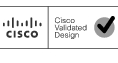
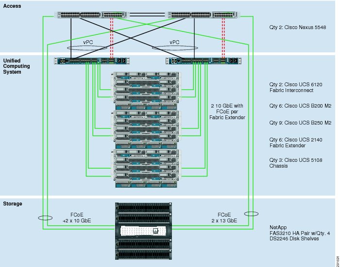
Specifically, FlexPod is a defined set of hardware and software that serves as a foundation for data center deployments. FlexPod includes NetApp storage, Cisco networking, and the Cisco Unified Computing System in a single package in which the computing and storage fit in one data center rack and the networking resides in a separate rack. Due to port density the networking components can accommodate multiple instances of FlexPod systems. Figure 1 shows the FlexPod components.
The solution can be scaled while still maintaining its integrity, either by adding more FlexPod units or by adding to the solution components. A number of solutions can be built on top of one or more FlexPod units, providing enterprise flexibility, supportability, and manageability.
Figure 1 and Figure 2 outline the possible NetApp Filer interconnect choices. The first topology in Figure 1 is an FCoE-only implementation, while the second in Figure 2 adds the option of native FC connectivity. These interconnects are not interdependent and may be deployed together or separately to meet customer hypervisor or application support requirements. Both deployments are fully supported.
Figure 1 FlexPod FCoE and 10 GbE Based Architecture
Figure 2 FlexPod FC and 10 GbE Based Architecture
The default hardware is detailed in the FlexPod technical specifications and includes two Cisco Nexus 5548 switches, two Cisco UCS 6120 fabric interconnects, and three chassis of Cisco UCS blades with two fabric extenders per chassis. Storage is provided by a NetApp FAS3210CC (HA configuration within a single chassis) with accompanying disk shelves. All systems and fabric links feature redundancy, providing end-to-end high availability. This is the default base design, but each of the components can be scaled flexibly to support a specific customer's business requirements. For example, more (or different) blades and chassis could be deployed to increase compute capacity, additional disk shelves could be deployed to improve IO capacity and throughput, or special hardware or special hardware or software features may be added to introduce new features (such as NetApp FlashCache for dedupe-aware caching).
The remainder of this document guides the reader through the steps necessary to deploy the base architecture as shown above. This includes everything from physical cabling to compute and storage configuration.
FlexPod Configuration Deployment
The following section provides detailed information on configuring all aspects of a base FlexPod unit. Because the FlexPod architecture is flexible, the exact configuration detailed below may vary from customer implementations depending on specific requirements. Although customer implementations may deviate from the information that follows, the practices, features, and configurations below should still be used as a reference for building a customized FlexPod deployment.
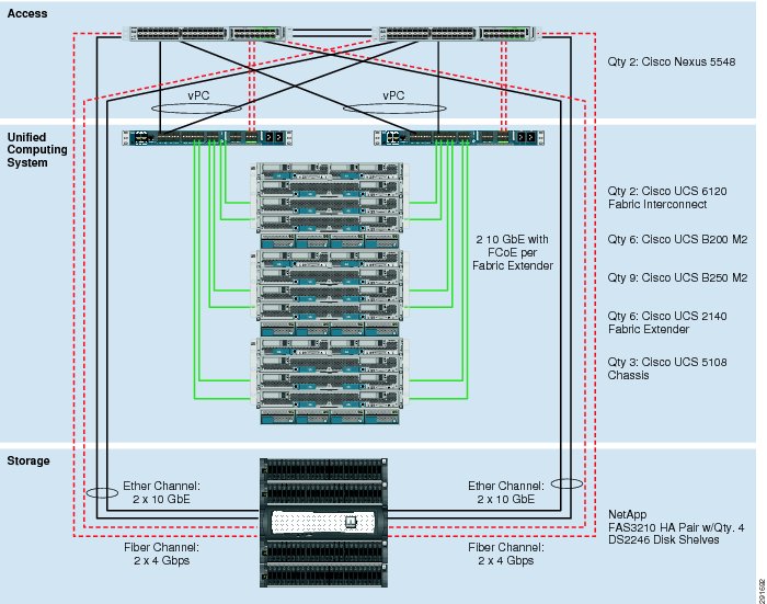
Cabling Information
The following information is provided as a reference for cabling the physical equipment in a FlexPod environment. The tables include both local and remote device and port locations to simplify cabling requirements.
Note
Note
Note
Note
Note
Note
Note
Note
Figure 3 FlexPod Cabling
NetApp FAS3210A Deployment Procedure—Part I
This section describes the procedures for configuring the NetApp FAS3210A for use in a FlexPod environment. This section has the following objectives:
•
•
•
•
•
The following measures should be taken to meet these objectives:
•
•
Note
•
•
•
•
•
•
•
•
•
•
•
•
•
•
•
•
•
•
•
•
•
•
•
Cisco Nexus 5548 Deployment Procedure—Part I
This section describes the procedures for deploying the Cisco Nexus 5548 platforms for use in a FlexPod system and achieves the following objectives:
•
•
•
The following actions are necessary to configure the Cisco Nexus 5548 switches for use in a FlexPod environment.
•
•
•
•
•
•
•
•
•
•
Cisco Unified Computing System Deployment Procedure
This section provides the procedure for configuring the Cisco Unified Computing System for use in a FlexPod environment. This workflow should achieve the following goals:
•
•
•
•
•
The following process should be followed for proper configuration.
•
•
•
•
•
•
•
•
•
•
•
•
•
•
•
•
•
•
•
•
•
•
•
•
•
•
Gather Necessary Information
Once the Cisco UCS Service Profiles have been created above, the infrastructure blades in the environment each have a unique configuration. To proceed with the FlexPod deployment, specific information must be gathered from each Cisco UCS blade as well as from the Netapp controllers. Table 3 and Table 4 detail the information that is needed for later use.
Table 3 NetApp FAS3210A FC Portname Information
NetApp FAS3210 A
0c or 2a
0d or 2b
NetApp FAS3210 B
0c or 2a
0d or 2b
Note
Cisco Nexus 5548 Deployment Procedure—Part II
This section describes the procedures for additional Fibre Channel functionality on the Cisco Nexus 5548 platforms within the FlexPod environment and achieves the following objectives:
•
•
•
The following measures should be taken on each Nexus platform:
•
•
•
•
•
•
•
•
•
NetApp FAS3210A Deployment Procedure—Part II
This section describes additional procedures necessary on the NetApp controllers to provide UCS stateless boot functionality. At the end of this workflow the following objectives should be met:
•
•
•
•
The following process outlines the steps necessary:
•
•
•
•
•
•
NetApp Operations Manager Deployment Procedure
There are a variety of choices available to manage the storage in a FlexPod environment, including NetApp FilerView, NetApp Virtual Storage Console (VSC), NetApp Operations Manager, and Microsoft Windows System Manager. The following section provides the general procedures for configuring NetApp Operations Manager, which is part of the DataFabric® Manager (DFM) 4.0 suite for use in a FlexPod environment. After completing this section the following should be available:
•
–
–
–
•
The following section provides the procedures for configuring NetApp Operations Manager for use in a FlexPod environment.
•
Note
•
•
•
•
•
•
•
•
Appendix—FlexPod Configuration Information
The following tables outline the information tht must be available to complete the setup and deployment of a FlexPod system.
Global Configuration Information
This information is used throughout the deployment across multiple layers in the environment.
NetApp Configuration Information
The information in Table 6 through Table 9 is specific to the NetApp portion of the deployment only.
Cisco Configuration Information
The information in Table 10 and Table 11 is specific to the Cisco portion of the deployment only.
NetApp FAS3200 Sample Configuration
Appliance Sample Interface Configuration
ntap3200-1a> ifconfig -ac0a: flags=0x354a867<UP,BROADCAST,RUNNING,MULTICAST,TCPCKSUM> mtu 9000 PRIVATEinet 192.168.1.85 netmask-or-prefix 0xffffff00 broadcast 192.168.1.255ether 00:a0:98:13:d2:d0 (auto-unknown-enabling) flowcontrol fullc0b: flags=0x3d4a867<UP,BROADCAST,RUNNING,MULTICAST,TCPCKSUM> mtu 9000 PRIVATEinet 192.168.2.135 netmask-or-prefix 0xffffff00 broadcast 192.168.2.255ether 00:a0:98:13:d2:d1 (auto-10g_kr-fd-up) flowcontrol fulle0M: flags=0x694c867<UP,BROADCAST,RUNNING,MULTICAST,TCPCKSUM,NOWINS> mtu 1500inet 10.61.185.144 netmask-or-prefix 0xffffff00 broadcast 10.61.185.255partner e0M (not in use)ether 00:a0:98:13:d2:d2 (auto-100tx-fd-up) flowcontrol fulle0P: flags=0x2d4c867<UP,BROADCAST,RUNNING,MULTICAST,TCPCKSUM> mtu 1500inet 192.168.2.48 netmask-or-prefix 0xfffffc00 broadcast 192.168.3.255 noddnsether 00:a0:98:13:d2:d3 (auto-100tx-fd-up) flowcontrol fulle0a: flags=0x250c866<BROADCAST,RUNNING,MULTICAST,TCPCKSUM> mtu 1500ether 00:a0:98:13:d2:ce (auto-unknown-cfg_down) flowcontrol fulle0b: flags=0x250c866<BROADCAST,RUNNING,MULTICAST,TCPCKSUM> mtu 1500ether 00:a0:98:13:d2:cf (auto-unknown-cfg_down) flowcontrol fulle2a: flags=0x8bd0a867<BROADCAST,RUNNING,MULTICAST,TCPCKSUM,VLAN> mtu 9000ether 02:a0:98:13:d2:d0 (auto-10g_sr-fd-up) flowcontrol fulltrunked vif0e2b: flags=0x8bd0a867<BROADCAST,RUNNING,MULTICAST,TCPCKSUM,VLAN> mtu 9000ether 02:a0:98:13:d2:d0 (auto-10g_sr-fd-up) flowcontrol fulltrunked vif0lo: flags=0x1948049<UP,LOOPBACK,RUNNING,MULTICAST,TCPCKSUM> mtu 8160inet 127.0.0.1 netmask-or-prefix 0xff000000 broadcast 127.0.0.1ether 00:00:00:00:00:00 (RNIC Provider)vif0: flags=0xa3d0a863<BROADCAST,RUNNING,MULTICAST,TCPCKSUM,VLAN> mtu 9000ether 02:a0:98:13:d2:d0 (Enabled virtual interface)vif0-900: flags=0x394a863<UP,BROADCAST,RUNNING,MULTICAST,TCPCKSUM> mtu 9000inet 192.168.90.144 netmask-or-prefix 0xffffff00 broadcast 192.168.90.255partner vif0-900 (not in use)ether 02:a0:98:13:d2:d0 (Enabled virtual interface)Sample Startup Information Configuration
ntap3200-1a> rdfile /etc/rchostname ntap3200-1avif create lacp vif0 -b ip e1a e1bvlan create vif0 3150 900ifconfig e0M `hostname`-e0M netmask 255.255.255.0 mtusize 1500 -wins flowcontrol full partner e0Mroute add default 10.61.185.1 1routed onoptions dns.domainname rtp.netapp.comoptions dns.enable onoptions nis.enable offsavecorevlan create vif0 900ifconfig vif0-900 mtusize 9000ifconfig vif0-900 partner vif0-900ifconfig vif0-900 192.168.90.144 netmask 255.255.255.0vlan add vif0 3150ifconfig vif0-3150 `hostname`-vif0-3150 netmask 255.255.255.0 mtusize 1500 -wins partner vif0-3150ifconfig vif0-3150 192.168.150.1 netmask 255.255.255.0Sample Volume Information
ntap3200-1a> vol statusVolume State Status Optionsinfrastructure_root online raid_dp, flex guarantee=none,fractional_reserve=0vol0 online raid_dp, flex rootinfrastructure_datastore_1 online raid_dp, flex guarantee=none,sis fractional_reserve=0esxi_boot_A online raid_dp, flex guarantee=none,sis fractional_reserve=0Sample LUN Information
ntap3200-1a> lun show -mLUN path Mapped to LUN ID Protocol-----------------------------------------------------------------------/vol/esxi_boot_A/ucs2b-1-sc ucs2b-1-sc_A 0 FCPucs2b-1-sc_B 0 FCPSample Initiator Group (iGroup) Information
ntap3200-1a> igroup showucs2b-1-sc_A (FCP) (ostype: "Hypervisor or Bare Metal":20:00:00:25:b5:00:0a:9f (logged in on: 0c)ucs2b-1-sc_B (FCP) (ostype: "Hypervisor or Bare Metal"):20:00:00:25:b5:00:0b:df (logged in on: 0d)Sample vFiler Unit Structure
ntap3200-1a> vfiler statusvfiler0 runninginfrastructure_1_vfiler runningSample List of Defined ipspaces and Interface Assignment
ntap3200-1a> ipspace listNumber of ipspaces configured: 3default-ipspace (e0M e0P e0a e0b )infrastructure (vif0-900 )Sample vFiler Unit Context Route Configuration
infrastructure_1_vfiler@ntap3200-1a> route -sRouting tablesInternet:Destination Gateway Flags Refs Use Interface192.168.90 link#12 UC 0 0 vif0-900192.168.90.109 0:50:56:70:f8:9a UHL 2 409 vif0-900192.168.90.110 0:50:56:77:8a:ac UHL 2 5181 vif0-900192.168.90.111 0:50:56:70:c0:80 UHL 2 9 vif0-900192.168.90.112 0:50:56:7b:df:f9 UHL 2 9 vif0-900192.168.90.117 0:50:56:a0:0:0 UHL 0 18 vif0-900Sample vFiler Unit Context Exported Directories and Files
infrastructure_1_vfiler@ntap3200-1a> exportfs/vol/infrastructure_datastore_1-sec=sys,rw=192.168.90.109:192.168.90.110:192.168.90.111:19 2.168.90.112:192.168.95.10,root=192.168.90.109:192.168.90.110:192.168.90.111:192.168.90.11 2:192.168.95.10/vol/infrastructure_root-sec=sys,rw,anon=0Cisco Nexus 5548 Sample Running Configuration
!Command: show running-config!Time: Wed Aug 10 11:35:26 2011version 5.0(3)N1(1c)feature fcoefeature npivfeature fport-channel-trunkno feature telnetno telnet server enablecfs eth distributefeature lacpfeature vpcfeature lldpusername admin password 5 $1$JpsspOIX$jk0ujNUh8cxcm2b7lOEaG0 role network-adminip domain-lookupswitchname ice5548-1system jumbomtu 9000logging event link-status defaultip access-list classify_COS_410 permit ip 192.168.102.0/24 any20 permit ip any 192.168.102.0/24ip access-list classify_COS_510 permit ip 192.168.101.0/24 any20 permit ip any 192.168.101.0/24class-map type qos class-fcoeclass-map type qos match-all Silver_Trafficmatch access-group name classify_COS_4class-map type qos match-all Platinum_Trafficmatch access-group name classify_COS_5class-map type queuing class-fcoematch qos-group 1class-map type queuing class-all-floodmatch qos-group 2class-map type queuing class-ip-multicastmatch qos-group 2policy-map type qos Global_Classifyclass Platinum_Trafficset qos-group 2class Silver_Trafficset qos-group 4class class-fcoeset qos-group 1class-map type network-qos class-fcoematch qos-group 1class-map type network-qos class-all-floodmatch qos-group 2class-map type network-qos Silver_Traffic_NQmatch qos-group 4class-map type network-qos class-ip-multicastmatch qos-group 2class-map type network-qos Platinum_Traffic_NQmatch qos-group 2policy-map type network-qos Setup_QOSclass type network-qos Platinum_Traffic_NQset cos 5mtu 9000class type network-qos Silver_Traffic_NQset cos 4mtu 9000class type network-qos class-fcoepause no-dropmtu 2158class type network-qos class-defaultmulticast-optimizesystem qosservice-policy type qos input Global_Classifyservice-policy type queuing input fcoe-default-in-policyservice-policy type queuing output fcoe-default-out-policyservice-policy type network-qos Setup_QOSsnmp-server user admin network-admin auth md5 0x91d2518e00e2d50e9e5d213bee818692 priv 0x91d2518e00e2d50e9e5d213bee818692 localizedkeysnmp-server enable traps entity fruntp server 10.61.185.11 use-vrf managementvrf context managementip route 0.0.0.0/0 10.61.185.1vlan 1vlan 101fcoe vsan 101name FCoE_Fabric_Avlan 186name MGMT-VLANvlan 3101name NFS-VLANvlan 3102name vMotion-VLANvlan 3103name Packet-Control-VLANvlan 3104name VM-Traffic-VLANspanning-tree port type edge bpduguard defaultspanning-tree port type edge bpdufilter defaultspanning-tree port type network defaultvpc domain 23role priority 10peer-keepalive destination 10.61.185.70 source 10.61.185.69vsan databasevsan 101 name "Fabric_A"device-alias databasedevice-alias name ice3270-1a_2a pwwn 50:0a:09:81:8d:dd:92:bcdevice-alias name ice3270-1b_2a pwwn 50:0a:09:81:9d:dd:92:bcdevice-alias name esxi41_host_ice3270-1a_2a1_A pwwn 20:00:00:25:b5:00:0a:0fdevice-alias name esxi41_host_ice3270-1b_2b1_A pwwn 20:00:00:25:b5:00:0a:1fdevice-alias commitfcdomain fcid databasevsan 1 wwn 20:42:00:05:9b:79:7a:80 fcid 0x800000 dynamicvsan 1 wwn 20:41:00:05:9b:79:7a:80 fcid 0x800001 dynamicvsan 101 wwn 50:0a:09:81:8d:dd:92:bc fcid 0x4e0000 dynamic! [ice3270-1a_2a]vsan 101 wwn 50:0a:09:81:9d:dd:92:bc fcid 0x4e0001 dynamic! [ice3270-1b_2a]vsan 101 wwn 20:42:00:05:9b:79:7a:80 fcid 0x4e0002 dynamicvsan 101 wwn 20:41:00:05:9b:79:7a:80 fcid 0x4e0003 dynamicvsan 101 wwn 20:00:00:25:b5:00:0a:0f fcid 0x4e0004 dynamic! [esxi41_host_ice3270-1a_2a1_A]vsan 101 wwn 20:00:00:25:b5:00:0a:1f fcid 0x4e0005 dynamic! [esxi41_host_ice3270-1b_2b1_A]interface san-port-channel 1channel mode activeinterface port-channel10description vPC peer-linkswitchport mode trunkvpc peer-linkswitchport trunk native vlan 2switchport trunk allowed vlan 186,3101-3104spanning-tree port type networkinterface port-channel11description ice3270-1aswitchport mode trunkvpc 11switchport trunk native vlan 2switchport trunk allowed vlan 101-102,186,3101spanning-tree port type edge trunkinterface port-channel12description ice3270-1bswitchport mode trunkvpc 12switchport trunk native vlan 2switchport trunk allowed vlan 101-102,186,3101spanning-tree port type edge trunkinterface port-channel13description iceucsm-2a-mswitchport mode trunkvpc 13switchport trunk native vlan 2switchport trunk allowed vlan 186,3101-3104spanning-tree port type edge trunkinterface port-channel14description iceucsm-2b-mswitchport mode trunkvpc 14switchport trunk native vlan 2switchport trunk allowed vlan 186,3101-3104spanning-tree port type edge trunkinterface port-channel20description Po20:iceds-1:Po12switchport mode trunkvpc 20switchport trunk native vlan 2switchport trunk allowed vlan 186spanning-tree port type!Command: show running-config!Time: Wed Aug 10 11:36:57 2011version 5.0(3)N1(1c)feature fcoefeature npivfeature fport-channel-trunkno feature telnetno telnet server enablecfs eth distributefeature lacpfeature vpcfeature lldpusername admin password 5 $1$PBq/n2.b$g8jK3jqj8MelNDQKGRBD50 role network-adminip domain-lookupswitchname ice5548-2system jumbomtu 9000logging event link-status defaultip access-list classify_COS_410 permit ip 192.168.102.0/24 any20 permit ip any 192.168.102.0/24ip access-list classify_COS_510 permit ip 192.168.101.0/24 any20 permit ip any 192.168.101.0/24class-map type qos class-fcoeclass-map type qos match-all Silver_Trafficmatch access-group name classify_COS_4class-map type qos match-all Platinum_Trafficmatch access-group name classify_COS_5class-map type queuing class-fcoematch qos-group 1class-map type queuing class-all-floodmatch qos-group 2class-map type queuing class-ip-multicastmatch qos-group 2policy-map type qos Global_Classifyclass Platinum_Trafficset qos-group 2class Silver_Trafficset qos-group 4class class-fcoeset qos-group 1class-map type network-qos class-fcoematch qos-group 1class-map type network-qos class-all-floodmatch qos-group 2class-map type network-qos Silver_Traffic_NQmatch qos-group 4class-map type network-qos class-ip-multicastmatch qos-group 2class-map type network-qos Platinum_Traffic_NQmatch qos-group 2policy-map type network-qos Setup_QOSclass type network-qos Platinum_Traffic_NQset cos 5mtu 9000class type network-qos Silver_Traffic_NQset cos 4mtu 9000class type network-qos class-fcoepause no-dropmtu 2158class type network-qos class-defaultmulticast-optimizesystem qosservice-policy type qos input Global_Classifyservice-policy type queuing input fcoe-default-in-policyservice-policy type queuing output fcoe-default-out-policyservice-policy type network-qos Setup_QOSsnmp-server user admin network-admin auth md5 0x7021e5331f25b481ed3ad26b96ccd729 priv 0x7021e5331f25b481ed3ad26b96ccd729 localizedkeysnmp-server enable traps entity fruntp server 10.61.185.11 use-vrf managementvrf context managementip route 0.0.0.0/0 10.61.185.1vlan 1vlan 102fcoe vsan 102name FCoE_Fabric_Bvlan 186name MGMT-VLANvlan 3101name NFS-VLANvlan 3102name vMotion-VLANvlan 3103name Packet-Control-VLANvlan 3104name VM-Traffic-VLANspanning-tree port type edge bpduguard defaultspanning-tree port type edge bpdufilter defaultspanning-tree port type network defaultvpc domain 23role priority 20peer-keepalive destination 10.61.185.69 source 10.61.185.70vsan databasevsan 102 name "Fabric_B"device-alias databasedevice-alias name ice3270-1a_2b pwwn 50:0a:09:82:8d:dd:92:bcdevice-alias name ice3270-1b_2b pwwn 50:0a:09:82:9d:dd:92:bcdevice-alias name esxi41_host_ice3270-1a_2a1_B pwwn 20:00:00:25:b5:00:0b:0fdevice-alias name esxi41_host_ice3270-1b_2b1_B pwwn 20:00:00:25:b5:00:0b:1fdevice-alias commitfcdomain fcid databasevsan 1 wwn 20:42:00:05:9b:6f:7a:40 fcid 0x590000 dynamicvsan 1 wwn 20:41:00:05:9b:6f:7a:40 fcid 0x590001 dynamicvsan 102 wwn 50:0a:09:82:9d:dd:92:bc fcid 0xae0000 dynamic! [ice3270-1b_2b]vsan 102 wwn 50:0a:09:82:8d:dd:92:bc fcid 0xae0001 dynamic! [ice3270-1a_2b]vsan 102 wwn 20:42:00:05:9b:6f:7a:40 fcid 0xae0002 dynamicvsan 102 wwn 20:41:00:05:9b:6f:7a:40 fcid 0xae0003 dynamicvsan 102 wwn 20:00:00:25:b5:00:0b:0f fcid 0xae0004 dynamic! [esxi41_host_ice3270-1a_2a1_A]vsan 102 wwn 20:00:00:25:b5:00:0b:1f fcid 0xae0005 dynamic! [esxi41_host_ice3270-1b_2b1_A]interface san-port-channel 2channel mode activeinterface port-channel10description vPC peer-linkswitchport mode trunkvpc peer-linkswitchport trunk native vlan 2switchport trunk allowed vlan 186,3101-3104spanning-tree port type networkinterface port-channel11description ice3270-1aswitchport mode trunkvpc 11switchport trunk native vlan 2switchport trunk allowed vlan 101-102,186,3101spanning-tree port type edge trunkinterface port-channel12description ice3270-1bswitchport mode trunkvpc 12switchport trunk native vlan 2switchport trunk allowed vlan 101-102,186,3101spanning-tree port type edge trunkinterface port-channel13description iceucsm-2a-mswitchport mode trunkvpc 13switchport trunk native vlan 2switchport trunk allowed vlan 186,3101-3104spanning-tree port type edge trunkinterface port-channel14description iceucsm-2b-mswitchport mode trunkvpc 14switchport trunk native vlan 2switchport trunk allowed vlan 186,3101-3104spanning-tree port type edge trunkinterface port-channel20description Po20:iceds-1:Po12switchport mode trunkvpc 20switchport trunk native vlan 2switchport trunk allowed vlan 186spanning-tree port type netCisco Unified Computing System Configuration Extracts
All configurations in this section occur after the initial UCS cluster setup scripts have completed and the UCS Manager is accessible to the administrator. Use the configuration information described above to execute the setup script and complete the deployment required in your environment.
For more information on the initial setup of Cisco UCS Manager, go to: http://www.cisco.com/en/US/products/ps10281/products_installation_and_configuration_guides_list.html and select the appropriate release of the "System Configuration" documentation.
Cisco Unified Computing System Configuration Examples and TechNotes
The latest Cisco UCS configuration examples and TechNotes may be found at: http://www.cisco.com/en/US/products/ps10281/prod_configuration_examples_list.html.
Sample Cisco Unified Computing System Initial CLI 1.4
The following video provides an example of the initial configuration of UCS from the command line interface: http://www.youtube.com/watch?v=86H_4lOeXfA&feature=related
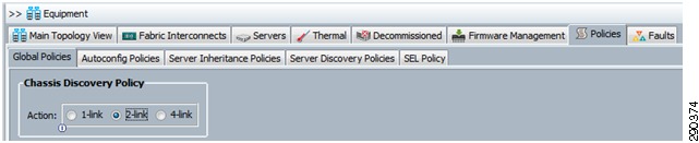
Sample Chassis Discovery Policy Configuration
Define the Chassis Discovery Policy to reflect the number of links from the chassis to the fabric interconnects. At a minimum FlexPod requires two links.
Figure 4 Chassis Discovery Policy Screen
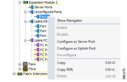
Define and enable Fibre Channel, Server, and Uplink Ports.
Figure 5 Fibre Channel Server and Uplink Ports Screen
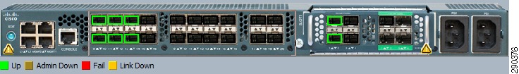
The physical display after completing this procedure is shown in Figure 6.
Figure 6 Physical Display after Procedure Completion
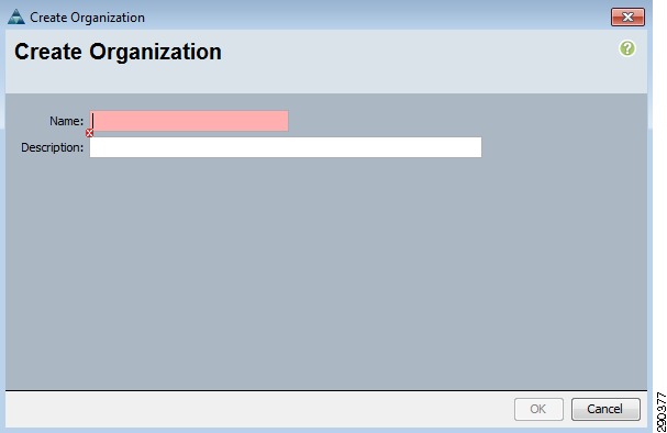
Create an Organization
The use of organizations allows the physical UCS resources to be logically divided. Each organization can have its own policies, pools, and quality of service definitions. Organizations are hierarchical in nature, allowing sub-organizations to inherit characteristics from higher organizations or establish their policies, pools, and service definitions.
To create an Organization, go to the Main panel New menu drop-down list and select Create Organization to create an organization which manages the FlexPod infrastructure and owns the logical building blocks.
Figure 7 Create Organization Screen
Cisco Unified Computing System—Working with Pools, Policies, and Templates
The following video provides examples and instructions for working with pools, policies, and templates for the Cisco Unified Computing System: http://www.youtube.com/watch?v=obmenIF4ggU&feature=related.
This UCS video covers the following topics.
Pools
Create MAC Address
Create vNIC
Create VLANs
Create VSANs
Create WWPNs
Servers
WWNN
UUID
Templates
vNIC
vHBA
Service Profile
Polices
QoS
Network Control
Pin Group
Boot
Power Control
Firmware
BIOS
Adapter
FC Port Channel and Trunking
The following video provides instructions and examples for setting up Fiber Channel port channel and trunking: http://www.youtube.com/watch?v=PpzKPguRTXc&feature=related.
Cisco Unified Computing System Block of IP Addresses for KVM Access
The following video provides instructions and examples for setting up the KVM address pool: http://www.youtube.com/watch?v=d0KTYItdU6g&NR=1.
References
•
•
•
•