Feedback Feedback
|
Table Of Contents
Cisco Virtual Workspace (VXI) Smart Solution 2.7 with Citrix XenDesktop 5.6
Cisco Virtual Workspace (VXI) Smart Solution Vision
Document Audience and Objectives
What is New in Cisco Virtual Workspace (VXI) Smart Solution 2.7
Cisco Virtual Workspace (VXI) Smart Solution Advantages
Cisco Virtual Workspace (VXI) Smart Solution Deployment Models
Virtualized Data Center Architecture
Compute Subsystem Design and Best Practices
Compute Subsystem Building Blocks
Connectivity for Cisco UCS Servers
Deploying Cisco UCS Fabric Interconnects
Server Topology Recommendations
Determining Cisco UCS BIOS Settings for Desktop Virtualization
Virtualization Design and Best Practices
Storage Design and Best Practices
Storage Capacity Best Practices
VLANs for the Virtualized Data Center
Virtualized Data Center Management
Cisco Network Deployment Models
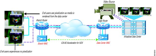
Cisco Wide Area Application Services
Endpoint Access Services in the Branch Office
Cisco Virtual Workspace Data Center Edge
Cisco Trustsec for Cisco Virtual Workspace (VXI) Smart Solution
WAN Optimization for Virtual Workspace
Citrix Multi-stream ICA (HDX Multi-Stream)
Configuring Cisco WAAS in a Cisco Virtual Workspace Environment
Configuring Traffic Interception for Cisco WAAS Using WCCP
Virtual Machine-Based Network Optimization: Cisco vWAAS
WAN Stability and Path Optimization
QoS for Multi-stream ICA (HDX Multi-Stream)
QoS for multi-stream ICA UDP Streams
Managing the Cisco Virtual Workspace Network
Cisco Virtual Workspace Clients
Cisco VXC 6215 Media Termination Capability
Design Considerations for the Cisco VXC Manager
Desktop Virtualization Endpoint Printing using Network Printer
Desktop Virtualization Endpoint Access to USB-attached Peripherals (Storage or Printing)
Rich Media, Collaboration and User Experience
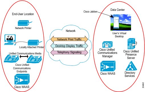
Rich Media and Collaboration in Traditional Virtual Desktop Infrastructure Environments
Rich Media and Collaboration in Cisco Virtual Workspace (VXI) Smart Solution
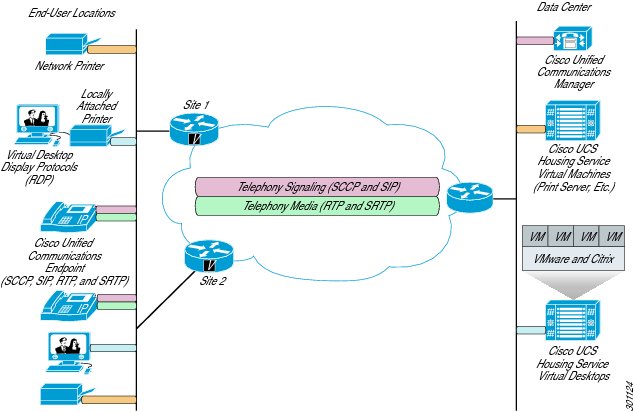
IP Telephony and Interactive Voice and Video Traffic Separation
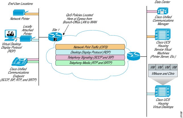
Display Protocol Traffic Separation
Contact Center Applications in Cisco Virtual Workspace (VXI) Smart Solution
Cisco Unified Communications Applications
Unified Communications Endpoint Single Sign-On
Cisco Unified Communications Applications, HVD, and Cisco Unified SRST
Cisco Virtual Workspace (VXI) and BYOD Smart Solutions
Unified Communications Enabled Accessories
Securing Cisco Virtual Workspace
Cisco Virtual Workspace End-to-End Security Architecture
Secure Unified Workspace: Design and Best Practices
Secure Access to the Enterprise
Secure Borderless Networks: Design and Best Practices
Secure Access for Fixed Teleworker and Home-User Environments
Secure Remote Access for Mobile Environments
Data Center Security - Design and Best Practices
User and Data Security for the Virtual Desktop
Securing the Virtual Desktop within the Data Center
Capacity Planning for Hosted Virtual Desktops: Computing and Storage
Resource Use in the Current Environment
Estimating Resource Requirements in a Virtualized Environment
Estimating Memory Requirements
Estimating Storage Requirements
Design Considerations: Computing
Power Management Considerations
High-Availability Considerations: Computing
Design Considerations: Storage
Thin Provisioning vs. Thick Provisioning
Storage Optimization Technologies
Cisco Knowledge Worker+ Profile
Validation Methodology and Results
Workload Profile: Cisco Knowledge Worker+
Cisco Nexus 1000V Series Switches
Cisco Virtual Security Gateway
Cisco Application Control Engine (ACE)
Cisco Adaptive Security Appliance (ASA)
Cisco Wide Area Application Services (WAAS)
Network - WAN Capacity Planning
Network Characterization Results
Scaling Cisco Virtual Workspace using XenApp Hosted Shared Desktops
Design Considerations for Management Tools
Cisco Virtual Workspace (VXI) Smart Solution Management Tool Summary
Cisco Virtualization Experience Clients
Citrix XenDesktop 5.6 Management Suite
Guidelines for Using Citrix XenDesktop Management suite
Desktop Monitoring and Assessment
Cisco Virtual Workspace (VXI) Smart Solution 2.7 with Citrix XenDesktop 5.6
April 2, 2013
Contents
List of Figures
List of Tables
About Cisco Validated Design (CVD) Program
The CVD program consists of systems and solutions designed, tested, and documented to facilitate faster, more reliable, and more predictable customer deployments. For more information visit http://www.cisco.com/go/designzone.
ALL DESIGNS, SPECIFICATIONS, STATEMENTS, INFORMATION, AND RECOMMENDATIONS (COLLECTIVELY, "DESIGNS") IN THIS MANUAL ARE PRESENTED "AS IS," WITH ALL FAULTS. CISCO AND ITS SUPPLIERS DISCLAIM ALL WARRANTIES, INCLUDING, WITHOUT LIMITATION, THE WARRANTY OF MERCHANTABILITY, FITNESS FOR A PARTICULAR PURPOSE AND NONINFRINGEMENT OR ARISING FROM A COURSE OF DEALING, USAGE, OR TRADE PRACTICE. IN NO EVENT SHALL CISCO OR ITS SUPPLIERS BE LIABLE FOR ANY INDIRECT, SPECIAL, CONSEQUENTIAL, OR INCIDENTAL DAMAGES, INCLUDING, WITHOUT LIMITATION, LOST PROFITS OR LOSS OR DAMAGE TO DATA ARISING OUT OF THE USE OR INABILITY TO USE THE DESIGNS, EVEN IF CISCO OR ITS SUPPLIERS HAVE BEEN ADVISED OF THE POSSIBILITY OF SUCH DAMAGES.
THE DESIGNS ARE SUBJECT TO CHANGE WITHOUT NOTICE. USERS ARE SOLELY RESPONSIBLE FOR THEIR APPLICATION OF THE DESIGNS. THE DESIGNS DO NOT CONSTITUTE THE TECHNICAL OR OTHER PROFESSIONAL ADVICE OF CISCO, ITS SUPPLIERS OR PARTNERS. USERS SHOULD CONSULT THEIR OWN TECHNICAL ADVISORS BEFORE IMPLEMENTING THE DESIGNS. RESULTS MAY VARY DEPENDING ON FACTORS NOT TESTED BY CISCO.
The Cisco implementation of TCP header compression is an adaptation of a program developed by the University of California, Berkeley (UCB) as part of UCB's public domain version of the UNIX operating system. All rights reserved. Copyright © 1981, Regents of the University of California.
Cisco and the Cisco Logo are trademarks of Cisco Systems, Inc. and/or its affiliates in the U.S. and other countries. A listing of Cisco's trademarks can be found at http://www.cisco.com/go/trademarks. Third party trademarks mentioned are the property of their respective owners. The use of the word partner does not imply a partnership relationship between Cisco and any other company. (1005R)
Any Internet Protocol (IP) addresses and phone numbers used in this document are not intended to be actual addresses and phone numbers. Any examples, command display output, network topology diagrams, and other figures included in the document are shown for illustrative purposes only. Any use of actual IP addresses or phone numbers in illustrative content is unintentional and coincidental.
Cisco Virtual Workspace (VXI) Smart Solution
© 2013 Cisco Systems, Inc. All rights reserved.
Introduction
Executive Summary
This Cisco® Validated Design Guide provides design considerations and guidelines for deploying an end-to-end Cisco Virtual Workspace (VXI) Smart Solution. Cisco Virtual Workspace (VXI) Smart Solution is a service-optimized desktop virtualization system that spans the Cisco Data Center, Cisco Borderless Networks and Cisco Collaboration architectures to deliver a superior collaboration and superior quality multimedia user experience in a fully integrated, open, and validated desktop virtualization solution. This validated design enables organizations to accelerate the successful implementation of desktop and application virtualization with a unified collaborative workspace. The Cisco Virtual Workspace (VXI) Smart Solution helps reduce risks and costs, and delivers a superior user experience.
This guide discusses the solution as a whole, and describes subsystems in separate chapters. The chapters describe major functional groups such as data center, network, and endpoints, as well as pervasive system functions such as management and security.
Cisco Virtual Workspace (VXI) Smart Solution Vision
Cisco Virtual Workspace (VXI) Smart Solution delivers the new virtual workspace that unifies virtual desktops, voice and video, enabling IT to provide exceptionally flexible, secure workspace services with an uncompromised user experience.
Document Audience and Objectives
This guide is intended for use by IT engineers and architects considering the implementation of Cisco Virtual Workspace (VXI) Smart Solution, and anyone who wants to understand the design principles underlying the solution using Citrix XenDesktop and XenApp. This document provides design considerations and guidelines for deploying an end-to-end Cisco Virtual Workspace (VXI) Smart Solution. This solution places the user's computing environment in the data center, allowing it to be accessed through a variety of endpoints, integrating it with collaboration tools, and helping ensure a high-quality user experience.
Cisco Virtual Workspace (VXI) Smart Solution is based on many subsystems including the virtualized data center, the virtualization-aware network, and the virtualized workspace; for many customers, many of these subsystems are already deployed. This document focuses on design guidance specific to Cisco Virtual Workspace (VXI) Smart Solution needed to augment an existing infrastructure for desktop and application virtualization.
This document does not cover all the foundational technologies and reference designs for routing, switching, security, storage, and virtualization. Please see the Cisco Introduction to End to End Desktop Virtualization for more information. It refers to detailed documents that discuss those technologies and reference designs. The Cisco Virtual Workspace (VXI) Smart Solution 2.7 As-Deployed Reference Guide presents detailed configurations for validated devices. It lists specific software and hardware versions and includes complete device configurations and diagrams showing the topology used in testing.
What is New in Cisco Virtual Workspace (VXI) Smart Solution 2.7
•
Integration of Cisco UCS Storage Accelerator with 768GB of disk space for desktop storage optimization
•
•
•
•
•
•
•
Note
http://support.citrix.com/proddocs/topic/xenapp/ps-library-wrapper.html
Overview
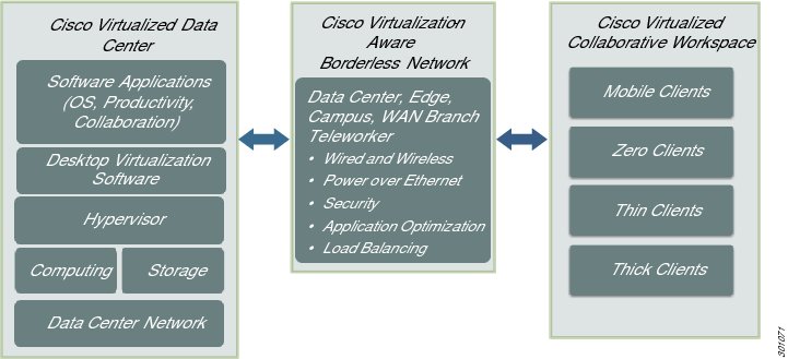
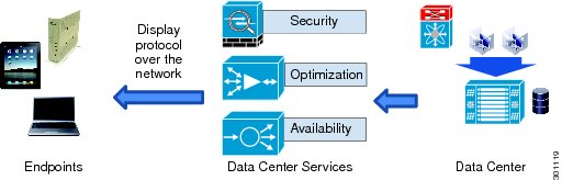
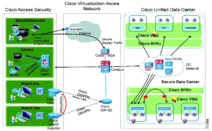
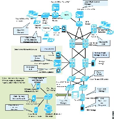
The Cisco Virtual Workspace (VXI) Smart Solution provides an optimized end-to-end infrastructure for desktop virtualization deployments. This system architecture consists of three fundamental building blocks: Cisco Virtualized Data Center, Virtualization-Aware Network, and Virtualized Collaborative Workspace (Figure 1).
The Cisco Virtualized Data Center is based on the Cisco Unified Data Center architecture, which creates data centers that are efficient, agile, and transformative. Cisco's Virtualized Data Center provides the computing, switching, storage, and virtualization capabilities needed to support a hosted virtual desktop solution from Citrix.
The Cisco Virtualization-Aware Network is based on the Cisco Borderless Networks architecture, which reduces operation complexity and provides the services needed to connect anyone, anywhere, on any device to his/her workspace. The Cisco Virtualization-Aware Network connects data centers, enterprise campuses, branch offices, and teleworkers to help ensure that traffic flowing between end users and their hosted desktops is transported securely, reliably, and efficiently. To achieve these goals, the network employs bandwidth optimization, load balancing, quality of service (QoS), security, and other technologies from Cisco's industry-leading portfolio.
The Cisco Virtualized Collaborative Workspace builds on the Cisco Collaboration architecture, extending the reach of the virtual desktop to a wide range of end points while supporting critical collaboration capabilities hosted in the data center. End points can be zero clients, thin clients, mobile devices or thick clients, and can include USB-based print and storage capabilities. The Cisco Virtualized Collaborative Workspace includes unique capabilities for integrating Cisco Unified Communications endpoints with hosted virtual desktops, including the control of Cisco IP Phones from virtual desktops.
Cisco Virtual Workspace (VXI) Smart Solution also supports management tools for both Cisco and ecosystem partner products, as well as a rich services portfolio that helps enterprises make the most of their virtualization investments.
Figure 1 Cisco Virtual Workspace (VXI) Smart Solution Architecture
Citrix Desktop and Application Virtualization for Cisco Virtual Workspace (VXI) Smart Solution
This Cisco Virtual Workspace (VXI) Smart Solution validated design is based on Citrix XenDesktop and XenApp virtualization solutions. Citrix XenDesktop is a desktop virtualization solution that delivers Windows desktops as an on-demand service to any user, anywhere. Citrix XenDesktop provides users with the flexibility to access their desktop on any device, anytime, with a high definition user experience. With XenDesktop, the IT department can manage single instances of each OS, application, and user profile and dynamically assemble these to increase business agility and greatly simplify desktop management. XenDesktop's open architecture enables customers to easily adopt desktop virtualization using any hypervisor, storage, or management infrastructure. This design guide validates the use of Citrix XenDesktop 5.6 for desktop virtualization.
Citrix XenDesktop includes a broad range of options for delivering virtualized Windows applications and desktops to the various types of users found within any given organization. These capabilities are grouped together under the term "FlexCast". XenDesktop FlexCast provides the customer with the flexibility to choose the right type of virtualized desktop or application solution for each user, and use case, found in the environment. Having this choice provides the customer with the right type of desktop virtualization solution for each user type (Power, Mobile, Task, etc.) in the organization, and helps reduce the overall cost of the solution as it provides less expensive options to the "one size fits all" approach found in VDI-only alternatives. FlexCast includes:
•
•
•
•
•
This Cisco Virtual Workspace (VXI) Smart Solution validates the use of Hosted Virtual (HVD) and Hosted Shared (XenApp delivered) desktops. Visit the Citrix FlexCast site for more information on those options: http://flexcast.citrix.com
Citrix XenApp, which is included as part of the XenDesktop license, is an on-demand application delivery solution that enables Windows® applications to be virtualized, centralized, and instantly delivered as a service to users anywhere on any device.
Cisco Virtual Workspace (VXI) Smart Solution Advantages
The validated design delivers the following critical advantages:
•
•
•
•
•
•
•
Plan
•
•
•
Build
•
•
Manage
•
•
Market Trends
Multiple trends are influencing the deployment of desktop virtualization: IT is seeking more virtualization and savings in the data center through cloud computing, IT is seeking better security and control in remote locations, and end users are seeking multimedia access from multiple devices and locations.
•
•
•
Cisco Virtual Workspace (VXI) Smart Solution Deployment Models
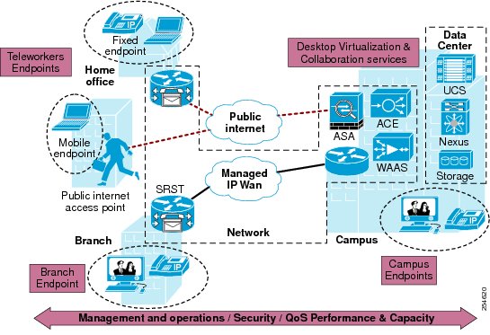
The Cisco Virtual Workspace (VXI) Smart Solution is fundamentally based on the centralization of the user's computing environment in the data center. The computing environment is virtualized and hosts the desktop virtualization (DV) and collaboration subsystems. Together, these subsystems provide the user community with desktop and telephony services delivered through the network to the various endpoints. These endpoints can be located on the enterprise campus, in branch or regional offices, home offices, or anywhere the user's mobile device has a network connection. Teleworkers are supported with both fixed and mobile clients. Figure 2 shows a typical deployment in which a wide range of clients access virtual desktops across the enterprise network. The term "enterprise network" refers to both the enterprise's own networking infrastructure, as well as its virtual private network (VPN) based extensions into the Internet, and other various forms of externally-managed commercial networks.
Figure 2 Top-Down View
Validation Goals and Summary
The collective sum of all components and sub-systems that make up the system is designed, deployed and tested in an integrated, end-to-end fashion that is reflective of a customer deployment. Design guidance provided throughout this document is based on this validation. Enterprises can leverage this guidance that includes best practices, caveats, scale, performance and other characterization data to plan and guide their own deployment. This information is primarily in this document but also in the following documents that serve as addendums to this document:
•
http://www.cisco.com/en/US/docs/solutions/Enterprise/Data_Center/VXI/CVD/VXI_PCV_C.pdf
•
•
http://www.cisco.com/en/US/customer/docs/solutions/Enterprise/Data_Center/VXI/VXI_RN_CPE.pdf
In the following tables include a high level summary of scalability, performance and other characterization testing performed in Cisco's labs. The testing provides key data needed for sizing a deployment and spans important aspects of the end to end system, specifically Compute, Storage, Collaboration applications, Rich Media and Network. Please refer to the above mentioned Results Guide for the actual results and data.
Compute and Storage Sizing
A series of scale and performance tests are done in the Cisco Virtual Workspace (VXI) Smart Solution to provide sizing data for common deployment profiles on different models of Cisco UCS servers. This includes both compute and storage aspects of desktop virtualization. Table 1 below provides a summarized view of these validation efforts.
Note
Table 1 Validation Goals and Summary
Scale and Performance characterization of Cisco UCS B200 M3 with Citrix XenApp Hosted Shared Desktops using a Cisco KW+ workload without antivirus
Cisco UCS B200 M3 with 384G of memory
NFS on NetApp FAS 3170
Citrix XenApp 6.5 on ESXi 5.1
Microsoft Windows 7 32-bit with 2 GB of memory and 24G disk; Persistent
Scale and Performance characterization of Cisco UCS B200M3 server with Citrix XenDesktop (FlexPod)
Cisco UCS B200 M3 with 384G of memory
NFS on NetApp FAS 3170
Citrix XenDesktop 5.6 FP1 (MCS) on ESXi 5.1
Microsoft Windows 7 32-bit with 2 GB of memory and 24G disk; Persistent
Impact of deploying Citrix PVS write cache on local SSDs
Cisco UCS B200 M3 with 384G of memory
NFS on NetApp FAS 3170
Citrix XenDesktop 5.6 FP1 (PVS 6.1) on ESXi 5.0 U1
Microsoft Windows 7 32b with 1.5G of memory and 24G disk; Non-persistent
Scale and Performance characterization of Cisco UCS B250M2 server (FlexPod)
Cisco UCS B250 M2 with 192G of memory
NFS on NetApp FAS 3170
Citrix XenDesktop5 on ESXi 5.0; ICA
Microsoft Windows 7 32b with 1.5G of memory and 24G disk; Persistent
Scale and Performance characterization of Cisco UCS B230M2 server (FlexPod)
Cisco UCS B230 M2 with 256G of memory
NFS on NetApp FAS 3170
Citrix XenDesktop 5.5 on ESXi 5.0; ICA
Microsoft Windows 7 32b with 1.5G of memory and 24G disk; Persistent
Scale and Performance characterization of Cisco UCS B250M2 server - Impact of Hyper-V Dynamic Memory
Cisco UCS B250 M2 with 192G of memory
NFS on NetApp FAS 3170
Citrix XenDesktop 5.5 on Microsoft HyperV 2008 R2 SP1
Microsoft Windows 7 32b with 1.5G of memory and 24G disk; Persistent
Storage Optimization (IOPS Offload) using Citrix Intellicache
Cisco UCS B-230 M2 with 256G of memory
NFS on NetApp FAS 3170
Citrix XenDesktop 5.5 on XS 6.0*
Microsoft Windows 7 32b with 1.5G of memory and 24G disk; Persistent
Note
Application Characterization
The goal of application characterization is to characterize the performance of the application as a standalone application in the workload, running across all user desktops deployed on a server. An Enterprise looking to deploy a Cisco Collaboration application for their virtual desktop users can use the performance data to understand the incremental impact of that application as more and more users start using them concurrently. The impact is to the server resources which can change the number of users that can be deployed on that same server once the new application is rolled out. Table 2 summarizes the application characterization results.
Table 2 Application Characterization
Network Characterization
The goal here is to characterize different network aspects of desktop virtualization, including network services, optimizations and other data needed for a successful deployment. A summary of these efforts, tested across a Cisco Virtual Workspace (VXI) Smart Solution are shown in Table 3.
Table 3 Network Characterization
Virtualized Data Center
Overview
The Virtualized Data Center unifies processor and storage resources, hosts virtual machines and desktops, and provides a network switching fabric that interconnects these resources to the rest of the enterprise network. It is based on Cisco Unified Data Center architecture, which creates data centers that are efficient, agile, and transformative. It helps enable enterprises to consolidate data center infrastructure, reduce energy costs, improve workforce productivity, and ensure business continuity. The Cisco data center is based on three pillars of innovation:
•
•
•
The Cisco Virtualized Data Center is highly scalable, and can be adopted in an incremental, granular fashion to help ensure a graceful evolution in response to enterprise needs. The virtualized data center is designed to provide optimum levels of performance, scalability, availability, and security. This section provides design guidance and best practices for achieving those goals in a deployment. The main topics include:
•
•
•
•
•
•
What Is New In Release 2.7
Release 2.7 validates the Cisco UCS Storage Accelerator for use with desktop virtualization deployments. The Cisco UCS Storage Accelerator is a PCIe Flash-based caching solution that resides on the Cisco UCS B200 M3 blade server. It supports extremely high numbers of IO requests and enables organizations to significantly reduce storage costs
Virtualized Data Center Architecture
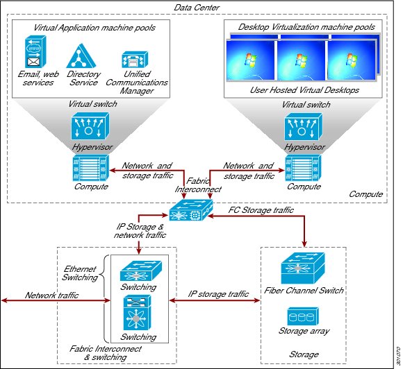
The Cisco Virtualized Data Center architecture consists of the computing, virtualization, storage, and networking subsystems needed to deliver an effective desktop virtualization solution. This structured approach to data center design provides outstanding flexibility as needs change, while helping ensure world-class performance, security, and resilience. The architecture tightly integrates Cisco and partner products, services, and best practices to provide a simplified, secure, and scalable solution (Figure 3).
Figure 3 Virtualized Data Center Architecture
Note
Compute Subsystem Design and Best Practices
The Compute subsystem is based on Cisco UCS components. The system combines Cisco UCS B-Series Blade Servers and C-Series Rack Servers with networking and storage access in a single converged system that simplifies management and delivers greater cost efficiency and agility with increased visibility and control. The Cisco UCS B-Series and C-Series servers support Cisco Unified Fabric, which connects computing, LAN, and storage networks through a single medium. Cisco UCS servers are designed to reduce energy consumption, with highly efficient power supplies and Intel Xeon processors that match power consumption with workloads. Each server contains the processor, RAM, and I/O resources needed to support a virtual desktop environment. Cisco UCS servers are managed by Cisco UCS Manager, which implements role-based and policy-based management using service profiles and templates. This section discusses the following important elements of the data center design:
•
•
•
•
•
•
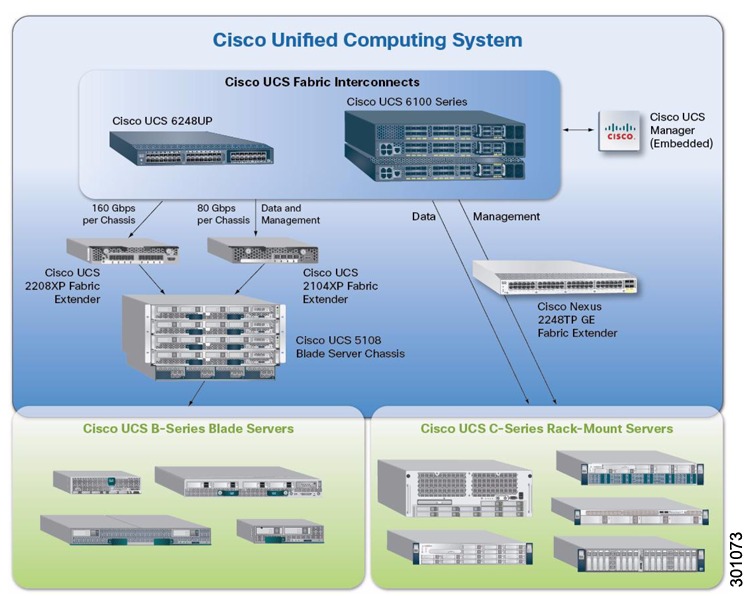
Compute Subsystem Building Blocks
•
•
•
•
•
•
Figure 4 Cisco Unified Computing System
Connectivity for Cisco UCS Servers
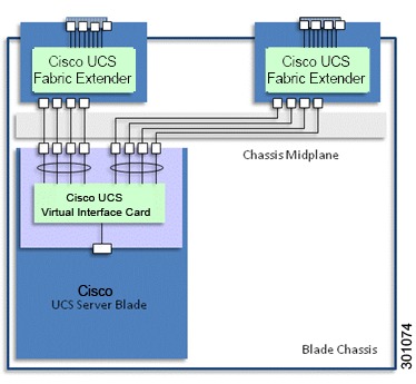
Cisco UCS B-Series Blade Servers connect to the chassis mid-plane by means of VICs installed as mezzanine cards (Figure 5). These cards provide virtual Ethernet Network Interface Cards (NIC)s or host bus adapters (HBAs) to the server operating system, and high-speed FCoE ports for connecting to Cisco UCS 2100 and 2200 Series Fabric Extenders located on the back of each chassis. The fabric extenders aggregate traffic from the interface cards and pass this traffic to an upstream pair of Cisco UCS Series 6100 or 6200 Series Fabric Interconnects (not shown).
Cisco UCS C-Series Rack Servers provide PCIe slots for network adapters (such as the VIC). These network adapters connect to Cisco Nexus 2200 Series Fabric Extenders, which in turn connect to the fabric interconnects. Alternately, Cisco UCS C-Series servers can be connected directly to a switch such as the Cisco Nexus 5500 switching platform.
Cisco UCS VICs can support advanced technologies such as Cisco Data Center Virtual Machine Fabric Extender (VM-FEX), which implements Cisco VN-Link in hardware. Cisco Data Center VM-FEX collapses physical and virtual switching layers, reduces the number of management points, and extends the network all the way to the virtual machine. Cisco Data Center VM-FEX is especially appropriate in environments in which hardware-based performance is more critical than high virtual machine density or virtualized service availability.
Cisco validated the VIC as a standard adapter without Cisco Data Center VM-FEX, using Cisco's software-based implementation of its VN-Link technology, the Cisco Nexus 1000V Series switches. The Cisco Nexus distributed virtual switches scale to very high densities, and support virtualized services such as the Cisco Virtual Security Gateway (VSG), as well as virtual firewalling and load balancing. The Cisco Nexus 1000V Series is discussed in greater detail in the networking portion of this chapter.
Figure 5 Cisco UCS B-Series Blade Server Connectivity
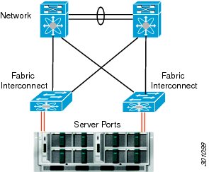
Deploying Cisco UCS Fabric Interconnects
The Cisco UCS 6100 and 6200 Series Fabric Interconnects are top-of-rack (ToR) controllers that provide network connectivity and management for Cisco UCS servers (Figure 6). Cisco fabric interconnects also function as parent switches for the fabric extenders, which act as distributed line cards. These fabric interconnects offer line-rate, low-latency, lossless 10 Gigabit Ethernet, Fibre Channel, and FCoE capabilities. The Cisco UCS 6100 and 6200 Series deliver high-performance unified fabric, centralized unified management with Cisco UCS Manager, and virtual machine-optimized services with support for Cisco VN-Link technology.
Fabric interconnects terminate FCoE traffic flows from the fabric extenders. Ethernet traffic is separated and forwarded to the data center switch fabric (composed of Cisco Nexus 5000 and 7000 Series Switches). Fibre Channel traffic is forwarded using Fibre Channel uplinks to the Fibre Channel SAN. The latest generation of fabric interconnects offers support for unified ports, which can be configured as either Ethernet or Fibre Channel ports.
Embedded Cisco UCS Manager facilitates management of the entire Cisco UCS domain. Using Cisco UCS Manager in combination with desktop virtualization management software, administrators can deploy virtual machines, perform software upgrades, migrate virtual machines between physical servers, and extend computing resource control over thousands of virtual desktops. For virtual environments, fabric interconnect design considerations include:
•
•
•
Figure 6 Cisco UCS 6x00 Fabric Interconnects
Server Topology Recommendations
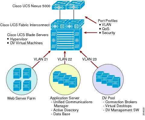
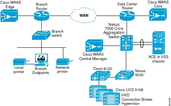
The validation process segregated infrastructure-oriented servers from servers that host virtual desktops. Infrastructure servers are those that provide critical services to a broad user population, such as application servers, license servers, unified communications, and Microsoft Active Directory. Grouping physical servers according to function and load helps ensure that resources are used more efficiently, and may protect infrastructure services from potential aggregate load effects and sudden surges. This approach also may insulate desktop users from demand peaks that might be associated with infrastructure servers. Figure 7 shows a deployment in which servers are grouped by function.
Figure 7 Grouping Servers by Function
Determining Cisco UCS BIOS Settings for Desktop Virtualization
Cisco UCS BIOS settings define basic server behavior during boot-up time. Some of these BIOS settings can directly affect system performance, especially in virtualized environments. Many of the most important parameters can be configured through Cisco UCS Manager. Table 4 shows the main BIOS parameters and the settings used for validation.
Table 4 Cisco UCS BIOS Settings
Note
Virtualization Design and Best Practices
The virtualization subsystem includes the various solutions required to virtualize servers, desktops, users, and applications in the system. The virtualization subsystem includes the following elements:
•
•
•
Hypervisor
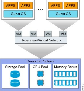
The hypervisor abstracts the processor, memory, storage, and networking resources of its physical server into multiple virtual machines, and helps ensure that each virtual machine receives its appropriate share of these resources (Figure 8). The hypervisor is installed on each Cisco UCS server to allow virtualized desktops and servers to run as independent virtual machines. Cisco has validated the following hypervisors for use with Citrix XenDesktop and XenApp:
•
•
•
Figure 8 Hypervisor
The hypervisor bridges the virtual and physical environments by interfacing virtual desktops with VICs on the blade servers. The VICs give the server (and thus the hypervisor) access to Ethernet NICs and Fibre Channel HBAs. Each card combines the Ethernet and Fibre Channel traffic on a unified fabric in the form of FCoE traffic. The hypervisor maps the physical NICs to vNICs as part of the virtual switch. Physical HBAs for Fibre Channel traffic are bridged directly to virtual HBAs (vHBAs).
Hypervisors include advanced tools for managing servers and associated virtual machines in high-density production environments. These tools enable IT administrators to identify overcommitted host machines, move virtual machines among pooled hosts, manage power-up sequences, consolidate active virtual machines on the fewest possible hosts, and more.
Many factors influence the successful deployment of a hypervisor, and a detailed discussion is beyond the scope of this document. Table 5 lists the main questions to consider when designing a hypervisor implementation for a Cisco environment.
Table 5 Main Questions When Designing a Hypervisor Installation
Virtual Machine topology definition
Physical and virtual resources can be grouped according to functions.
Management and infrastructure server applications are installed on dedicated Cisco UCS blades. Dedicated database servers host the VMware vCenter and VMware View databases. The VMware vSphere Enterprise Plus License is deployed on the VMware vCenter server.
Virtual resource provisioning
Virtualization enables a certain degree of over-provisioning, but too much over-provisioning can have diminishing returns. For example, provisioning a virtual machine with more virtual CPUs (vCPUs) than it can use will increase resource consumption and may actually reduce performance under some circumstances.
Virtual machines running a Microsoft Windows 7 or XP guest OS are provisioned with 1.5 to 2.0 GB RAM (with memory over-commit off) and 20 GB of disk space. See the Cisco Virtual Workspace (VXI) Smart Solution 2.7 Performance and Capacity Results Guide for Citrix for sizing virtual resource requirements.
Storage types
Storage can be physically located on the Cisco UCS blade server or network attached. To support virtual machine migration, clustering, distributed resource scheduling and other advanced virtualization features, shared storage is typically deployed. User preferences vary widely, and some deployments may use hybrid shared and local solutions.
The system includes support for shared storage solutions (network-attached storage [NAS] and SAN) from multiple ecosystem partners. Cisco has also validated hybrid storage solutions that blend both local and centralized share resources.
VM boot source
Booting from centralized shared storage allows for off-the-shelf server replacements as well as centralized configuration management of the hypervisor software.
The Cisco validated design is configured to boot from SAN, as recommended by the hypervisor vendor guidelines.
Disable unused physical devices
Hypervisor vendors typically recommend that unused devices such as COM, USB, and LPT1 ports, and optical drives be disabled. These devices consume resources even when not used. Some devices are polled even though inactive, or reserve blocks of memory that will not be used.
Cisco recommends disabling unused ports and drives so that these do not needlessly consume resources.
Advanced hypervisor configuration parameters (VMware)
Hypervisors may provide the capability to fine-tune CPU and memory resources in virtual machines, which can increase virtual machine density per server. In early versions of VMware vSphere, for example, tuning of CPU fairness algorithms and memory reclamation features was a manual process, performed only with the guidance of technical support. Newer (VMware vSphere 5.0 and later) versions have default values optimized for large deployments.
Cisco recommends deploying the most recent versions of these hypervisors to use optimized default settings.
Advanced hypervisor configuration parameters (Citrix)
Hypervisors increasingly provide caching features that cache temporary files and non-persistent virtual desktops on server local disks.This caching capability enables some virtual machine read and write operations to be executed on lower cost server storage, which conserves critical shared storage resources.
Citrix IntelliCache, along with Citrix Machine Creation Services (MCS) for thin provisioning, may reduce the load on centralized NAS and/or SAN resources.
Advanced hypervisor configuration parameters (Microsoft)
Microsoft Hyper-V provides a dynamic memory management capability that balances memory use among running virtual machines.
With Microsoft Hyper-V, virtual machines can be configured with a memory range, rather than just a fixed memory allocation. Administrators can set memory priorities for virtual machines so that memory can be removed from low priority machines and reallocated to higher priority machines. This capability can increase the number of virtual machines that can be supported on each server.
Compatibility issues between VMware ESXI 5 Update 1 and Citrix XenDesktop (5.0 SP1, 5.5, 5.6, 5.6 FP1)
Users should be aware of issues and workarounds involving these combinations.
System synchronization
System-wide synchronization is critical to help ensure the accuracy of all logged information.
Cisco recommends synchronizing the hypervisor clock to an external Network Time Protocol (NTP) server, and then synchronizing the virtual desktop operating system clocks to the hypervisor clock.
High availability
Hosts can be clustered to provide fault tolerance and high availability.
A system best practice is to distribute hosts across multiple Cisco UCS chassis to provide better availability in the event of a chassis failure; at the same time, all hosts are grouped in a single high-availability cluster.
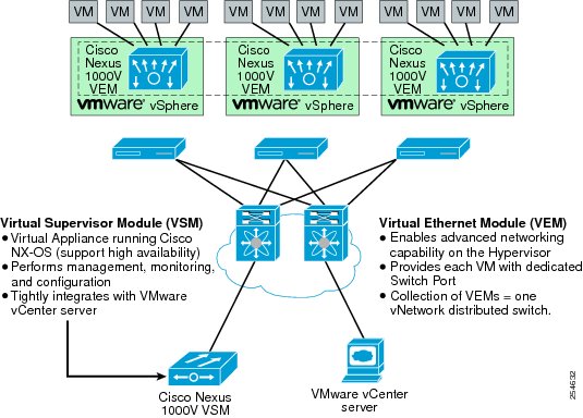
Virtual Switching for Hypervisors: Cisco Nexus 1000v Switch
The Cisco Nexus 1000V Switch is a virtual machine access switch that runs inside a hypervisor. The switch uses Cisco VN-Link server virtualization technology to deliver policy-based virtual machine connectivity, mobile virtual machine security and network policy, and a nondisruptive operation model. The Cisco Nexus 1000V provides administrators with a consistent networking feature set and provisioning process from the virtual machine access layer to the data center network core. Virtual servers can use the same network configuration, security policy, diagnostic tools, and operation models as their physical server counterparts.
A single Cisco Nexus 1000V Switch can encompass several physical servers. Targeted port profiles can be created for the specific requirements associated with each type of user and virtual desktop. Cisco Nexus 1000V profiles contain information such as VLAN assignment, quality-of-service (QoS) policies, and security access control lists (ACLs). The port profile is linked to the virtual machine profile, so that if the hypervisor migrates to a particular virtual desktop, the associated profile also migrates.
Troubleshooting of connectivity problems is enhanced through the built-in Cisco Switched Port Analyzer (SPAN). Increased security is implemented by the use of several additional features such as VLANs, private VLANs, port security, and security ACLs. The Cisco Nexus 1000V also provides a foundation for other virtual networking solutions such as the Cisco VSG and Cisco Virtual Wide Area Application Services (vWAAS) . The Cisco Nexus 1000V is currently supported on VMware vSphere hypervisors with Enterprise Plus licenses (Figure 9).
Figure 9 VMware ESX/ESXi and Cisco Nexus 1000V Series Integration
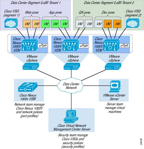
Virtual Machine-Based Security Zones: The Cisco Virtual Security Gateway
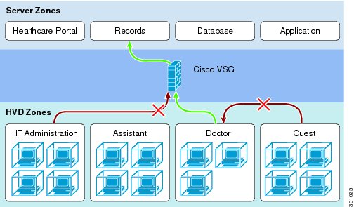
Cisco VSG for Cisco Nexus 1000V Series Switches is a virtual appliance that controls and monitors access to trust zones in enterprise and cloud provider environments (Figure 10). Cisco VSG provides secure segmentation of virtualized data center virtual machines using detailed, zone-based control and monitoring with context-aware security policies. Controls are applied across organizational zones, lines of business, or multitenant environments. Context-based access logs are generated with network and virtual machine activity levels. Trust zones and security templates can be provisioned on demand as virtual machines are created. Refer to the Securing Cisco Virtual Workspace chapter of this guide for more information on creating and deploying security zones.
Cisco VSG employs Cisco Virtual Network Service Data Path (vPath) technology embedded in the Cisco Nexus 1000V Series Virtual Ethernet Module (VEM). Cisco vPath steers traffic to the designated Cisco VSG for initial policy evaluation and enforcement. Subsequent policy enforcement is off-loaded directly to Cisco vPath. Cisco VSG can provide protection across multiple physical servers. It can be transparently inserted in one-arm mode, and it offers an active-standby mode for high availability.
Cisco VSG can be deployed across multiple virtual machine zones and virtualized applications. It requires a virtual 1.5-GHz CPU, 2 GB of RAM, a 3-GB hard drive, and three network interfaces (data, management, and high availability). It also requires VMware vSphere and vCenter Release 4.0 or later, Cisco Nexus 1000V VEMs and VSMs, and Cisco Virtual Network Management Center (VNMC).
Figure 10 Cisco Virtual Security Gateway
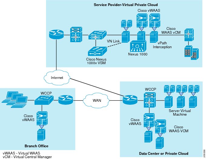
Virtual Machine-Based Network Optimization: Cisco vWAAS
Cisco vWAAS is a virtual appliance that accelerates business applications delivered from private and virtual private clouds. Cisco vWAAS runs on Cisco UCS servers and the VMware vSphere hypervisor, using policy-based configuration in the Cisco Nexus 1000V Switch. Cisco vWAAS can be associated with application server virtual machines as these are instantiated or moved. With Cisco vWAAS, cloud providers can rapidly provision WAN optimization services with little to no configuration or disruption.
For more information on Cisco vWAAS, see the Virtualization Aware Network and Scaling and High Availability chapters, in this guide.
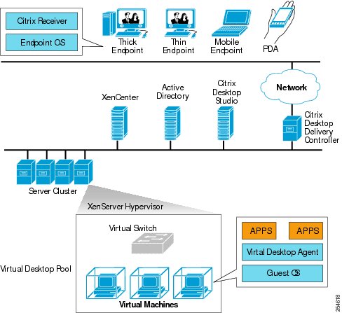
Desktop Virtualization
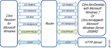
This Cisco Validated Design guide describes the implementation of this solution with the Citrix XenDesktop solution for desktop virtualization. With Citrix XenDesktop, organizations can create and run virtual desktops in the data center, and deliver these desktops to employees using a wide range of endpoints. Users access their virtual desktops from zero, thin, or thick clients by means of the Citrix Independent Computing Architecture (ICA) remote display protocol. Figure 11 shows a typical desktop virtualization implementation based on Citrix XenDesktop.
Figure 11 Citrix XenDesktop Desktop Virtualization Deployment
Hosted Virtual Desktop
Hosted virtual desktops (HVDs) in a Citrix XenDesktop environment can be deployed in multiple modes, such as dedicated, pooled, streamed, shared, or personal vDisks (streamed or pooled). These modes are differentiated based on the way that end users access and associate with the virtual desktop. Another way to differentiate HVDs is based on the state of virtual desktops across multiple user logins in which the two modes are persistent one-to-one or nonpersistent desktops. Persistent desktops are tied to a specific user and generally have customizations and user data preserved through the life of the desktop. Nonpersistent desktop pools allow better scalability by creating an oversubscribed pool of desktops shared across users. These desktops are assigned to the user at login. Customizations and user data, if present in a separate data store, are applied, and when the user logs off, the desktops are released in the pool for other users. Nonpersistent desktops are recommended for task workers who require temporary computing platform to access various enterprise applications and are not expected to store user data locally.
Citrix Virtual Desktop Agent
Citrix Virtual Desktop Agent (VDA) is installed on each HVD. The agent makes the desktop available to the endpoint client. The agent receives ICA connection requests on port 1494, prepares the desktop, and streams it to the client. It also registers the HVD with the desktop delivery controller (DDC). In the background, the Citrix VDA communicates with the DDC to update session status and provide usage statistics. The Citrix VDA uses port 8080 to communicate with DDC.
Citrix Online Plug-in
Citrix provides multiple client software options for use with the Citrix VDA. Depending on the endpoint hardware, the Citrix Receiver, the Online Plug-in or the Self-service plug-in can be used. The Citrix Online Plug-in provides toolbar functions, enabling users to pan and scale virtual desktops from their local desktop. Users can work with more than one desktop by using multiple Citrix Online Plug-in sessions on the same device. See Citrix product documentation for details.
Citrix XenDesktop Controller
Citrix XenDesktop Controller is the central piece of a Citrix XenDesktop environment, and among other functions it includes a connection broker service that performs user authentication, virtual machine power management, and so on. On session establishment, it also makes Citrix HDX policy decisions and enforces any licenses, as needed. After the connection between the client and the agent is established, Citrix XenDesktop does out-of-band monitoring with assistance from the agent. Citrix XenDesktop can scale to handle many thousands of desktops on a single installed instance.
The server also performs data collection functions that can be valuable for auditing and for making desktop virtualization deployment adjustments. Administrators can create Citrix XenDesktop sites in which each controller is assigned a specialized function, such as data collection and infrastructure control. For high availability, multiple Citrix XenDesktop host servers can be deployed running broker services in the environment, preferably behind a load balancer such as the Cisco Application Control Engine (ACE) Module. Citrix XenDesktop requires that all site members be part of the same Microsoft Active Directory domain. The solution now integrates a virtual machine management server that can also create and provision virtual desktops in real time. For environments in which persistent desktops are not needed, the provisioning services can significantly optimize the storage use.
Citrix Provisioning Server
The Citrix Provisioning Server is a component that creates and provision virtual desktops from a single desktop image on demand, optimizing storage utilization and providing a pristine virtual desktop to each user every time they log on. Desktop provisioning with the Citrix Provisioning Server also simplifies desktop images, provides outstanding flexibility, and offers fewer points of desktop management for both applications and desktops.
Citrix Personal vDisk Technology
Citrix Personal vDisk technology allows for reduced storage costs by enabling the customer to leverage a single base operating system image across multiple virtual desktop users while still providing those users with a personal, virtual disk on which to store their profile, preferences, data and even user-installed applications. This provides the benefits found in pooled desktop image management (i.e. a single OS image to manage for multiple desktop users) while maintaining a level of persistent personalization of the desktop for each particular user. With Citrix Personal vDisk technology administrators can update, patch and otherwise manage the underlying OS while the user's settings, applications and other customizations persist across updates to the layers underneath. Personal vDisks provide this separation by redirecting all changes made on the user's VM to a separate disk (i.e. the personal vDisk) attached to the user's VM. The content of the personal vDisk is blended at runtime with the content from the base VM to provide a unified image experience. In this way, users can still access applications provisioned by their administrator in the base VM. Please refer to Citrix documentation on this topic for more details: http://support.citrix.com/proddocs/topic/xendesktop-ibi/cds-about-personal-vdisks-ibi.html
Citrix Desktop Director
The Citrix Desktop Director provides a single console that IT administrators can use to monitor, troubleshoot, and assist users with virtual desktops and applications. This console can be used to assist users with Citrix XenDesktop-delivered virtual desktops, Citrix XenApp applications, and server hosted desktops.
Hosted Shared Desktops
Hosted Shared Desktops (HSDs) allow multiple users to share the same underlying guest operating system. HSDs are one of the most scalable ways to provide desktop services to users. Sharing is based on Microsoft Remote Desktop Services so the users are not completely isolated from each other. A large enterprise will typically use a mix of HVDs and HSDs. HSDs are published by Citrix XenApp 6.5. A farm of servers running the required desktops is created with XenApp running on each server. After the farm is created and all necessary applications are installed, the farm can be published on the existing Citrix XenDesktop web interface, or it can be published with a new web interface. Detailed deployment and configuration information for various Citrix XenApp deployment modes and an integration checklist can be found in the Citrix knowledge base.
To determine when to use HSDs or HVDs, Citrix recommends performing user segmentation analysis, categorizing the user base according to the applications needed for work, the resource intensiveness of those applications, and use patterns. Because hosted shared desktops share the underlying OS environment, a resource-intensive action performed by one user can affect resource availability for all other users. HSDs provide the maximum benefit to task-based workers for whom personalized desktops are not required.
Application Virtualization
Application virtualization "containerizes" and insulates applications from the guest operating system. This process permits a single virtualized application instance to run across different Microsoft Windows OS versions. It also helps ensure that malware infecting a virtualized application will not escape the container to infect the OS or other applications. Cisco has validated Citrix XenApp for application virtualization. Citrix XenApp centralizes the installation, storage, and delivery of applications within the data center. These applications can be delivered transparently on demand. Refer to the Cisco VXI Management and Operations chapter of this document as well as http://support.citrix.com/proddocs/topic/xenapp/ps-library-wrapper.html for more information.
Storage Design and Best Practices
Storage is one of the most critical elements of the virtualized data center. Analysts estimate that storage represents anywhere from 40% to 80% of the cost of a desktop virtualization investment, so designing an effective storage solution is essential to achieving Return-On-Investment goals. The storage system also has a major impact on desktop performance and user experience. With traditional desktop PCs, users have enjoyed fast, direct access to dedicated disks. With desktop virtualization, these storage resources become centralized and designers must consider the effects of latency and resource contention on the user population. Storage system design also influences the ability to scale to accommodate new users, as pilot programs expand to full-scale deployments. More users generate greater demand for storage resources, higher levels of I/Os per Second (IOPS), and higher latency. In short, the storage architecture is a significant factor in determining the success or failure of a virtualized desktop implementation.
Designing storage for desktop virtualization presents significant challenges in terms of cost and performance. It can be difficult to balance costs with capacity and IO access requirements. Organizations often over-provision their storage arrays, adding more disks than are needed to ensure sufficient levels of IO access. This tactic may preserve the user experience, but at great cost. Storage design is also complicated by the episodic nature of user access. Steady state operation, for example, may require only eight or ten IOPS per desktop. During a login storm, when large numbers of users login at about the same time, IOPS may burst to very high levels. Deploying sufficient storage to handle peak loads results in excess capacity during steady state operations. On the other hand, insufficient IOPS during peak load situations can cause significant delays for end users, as they are unable to access their desktops.
In virtualized environments, IO also tends to be highly random. The Windows operating system is designed to optimize IO operations so that blocks are written to (or read from) disk sequentially. This sequential operation minimizes the time required for disk reads/writes and improves performance. In the virtual world, hypervisors tend to produce smaller random blocks of IO (also known as the blender effect). These random IO operations have a significant impact on disk performance, and may introduce unacceptable levels of latency.
The goal of the storage system designer, then, is to implement a solution that is cost-effective, predictable, and responsive to sudden changes in workload. To that end, the storage architecture is designed to integrate a wide range of storage technologies and optimization techniques. Cisco design goals include -
•
•
•
Storage Deployment Models
This Smart Solution has validated three major approaches to implementing storage in a Citrix desktop virtualization deployment. These models include: (1) central shared storage, (2) local server-based SSD with central shared storage, and (3) local server-based Cisco UCS Storage Accelerator with central shared storage.
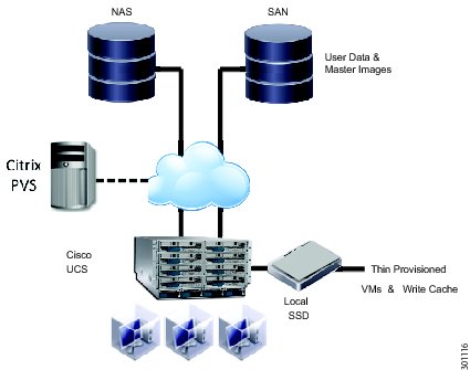
Central Shared Storage
Traditionally, virtualization vendors recommended centralized, shared storage systems for virtual desktop deployments. In this deployment model, the shared storage system contains the user's machine environment, including the operating system, user profiles, and user data (see Figure 12). These systems, based on high capacity storage arrays, offer centralized security, high performance, and resource sharing. Centralized shared storage also facilitates the use of advanced hypervisor features and aids in desktop migration.
The solution supports both Network-Attached Storage (NAS) and Storage Area Networks (SAN). Shared storage systems are provided by ecosystem partners EMC and NetApp. Each partner offers solutions that support both NAS and SAN. In the test environment, the EMC VNX system was deployed for SAN-based block storage, and the NetApp FAS system was configured for file-based NAS.
The EMC Unified Storage solution provides advanced failover and fully automated storage tiering to virtual desktop environments. EMC Unified Storage solutions can connect to multiple storage networks through NAS, Small Computer System Interface over IP (iSCSI), and Fibre Channel SANs. Cisco system testing validated the EMC Unified Storage solutions for SAN deployments. Hosts were configured to boot from the SAN.
The NetApp FAS Series is a unified storage solution that supports both SAN and NAS deployments. NetApp storage arrays are highly optimized for the intensive read and write workload typical of virtual desktop environments (see the product documentation for more information). NetApp storage runs the Data ONTAP operating system, which provides SAN (FCoE, Fibre Channel, and iSCSI), NAS (Common Internet File System [CIFS] and Network File System [NFS]), primary storage, and secondary storage on a single platform so that all virtual desktop components (virtual machine OS, user persona, user data, applications, data, etc.) can be hosted on the same unified storage array.
Deployment Notes
•
•
•
•
Figure 12 Centralized, Shared Storage
Local SSD and Central Shared Storage
This model takes advantage of solid-state drives (SSDs) on Cisco UCS servers to extend and complement the shared storage system. In this approach, non-persistent files and thin-provisioned VMs are stored locally on the Cisco UCS server SSDs. The SSD will also be used to provide a local write cache for the Citrix Provisioning Server (see Figure 13). User data and master images are maintained on shared storage. The objective is to reduce demand on the shared storage system by servicing many requests from the local SSD. This hybrid design is intended to provide a cost-effective solution for reducing storage costs.
During steady state operations (normal desktop usage), Write IO tends to be the predominate workload for storage systems. Write IO is also more expensive than Read IO in terms of resource consumption. In production-class desktop virtualization environments, large numbers of random Write operations can negatively impact storage performance. By moving the Write cache to the server SSDs, these Write operations are offloaded and addressed locally for improved performance.
Multiple SSDs can be deployed per server to scale the solution and further reduce the amount of traffic bound for the shared storage system. Cisco UCS B Series servers support a maximum of two SSDs, while some UCS C Series servers can support up to 24.
Deployment Notes
•
•
•
Figure 13 Local SSD and Shared Storage
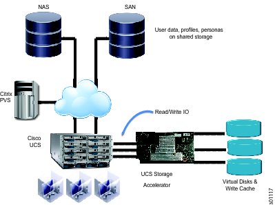
Cisco UCS Storage Accelerator and Central Shared Storage
The UCS Storage Accelerator is a Flash-based caching solution that resides on a Cisco UCS B200 M3 blade server. The accelerator is a 785 GB mezzanine card that delivers much higher levels of IOPS than a typical shared storage system. IO requests for a particular server are contained within that server, which reduces latency compared to traditional approaches. This enables network administrators to support a guaranteed number of users at a lower cost, and with predictable performance.
In this model, a golden master image and all associated clone images are hosted on the Cisco UCS Storage Accelerator, which is installed on the blade server. A central copy of the golden master image can be maintained on the shared storage system. User data, profiles, and personas are also saved on the shared system. This approach also improves scalability by enabling support for large numbers of users, while providing faster boot-up times.
Deployment Notes
•
•
•
•
Figure 14 Cisco UCS Accelerator and Shared Storage
Storage Capacity Best Practices
Storage capacity is the amount of disk space needed to accommodate the virtual machines used for desktop virtualization. Capacity requirements can be roughly estimated by multiplying the number of virtual machines by the size of the hard-disk space allocated per virtual machine. For example, with 100 virtual machines each having assigned a disk space of 30GB, 100 x 30GB= 3TB of data capacity would be required. Refer to the Scaling and High Availability chapter of this guide for information on storage capacity planning. Cisco also recommends working closely with both storage and virtualization vendors to help ensure that storage resources are used efficiently.
The storage arrays support various forms of thin provisioning. Thin provisioning is a form of over-subscription that makes storage available as needed. This capability enables higher storage use, and reduces the need to overprovision and preallocate physical disk capacity.
Storage arrays also typically provide the capability to identify and eliminate duplicate data from disks. With deduplication enabled, only unique data blocks are stored. Duplicate blocks are discarded, and their associated disk space is reclaimed. The deduplication process can be scheduled to run at specific intervals. A best practice is to run deduplication at off-peak intervals to reduce impact on application performance.
Storage requirements also can be reduced with features provided by the desktop virtualization solution. Citrix MCS, Citrix Provisioning Services (PVS), and Citrix Personal vDisk (PVD) all start from a single master image and thus can further reduce the amount of disk space consumed.
IOPS Best Practices
IOPS loads for virtualized environments can vary greatly. For example, when virtual machines boot up, much data needs to be read from disk. Other operations (such as logins and logoffs) generate a lot of disk write operations. IOPS loads are subject to large peaks, such as when a lot of users start using their virtual desktops at roughly the same time. Scheduled tasks such as virus scans and file index searching also can cause peaks in IOPS load.
To optimize read IOPS, master images that will be read by many virtual machines should be placed in a fast-access data store. Both EMC and NetApp storage solutions have been validated and provide technologies to cache the master image in the first and fastest level of cache on the storage array.
For write IOPS, many approaches are available for putting the right data in the right storage tier. With desktop virtualization, the data being written and reread is random, making it a challenge to increase performance and find the right balance between different types of disks. In this release, new designs have been validated to achieve the right balance between performance and cost. For Citrix PVS deployments, you can configure the location of the write cache, which provides flexibility in the use of Cisco UCS RAM and SSDs. With the recent increases in SSD capacity, this approach has become an attractive solution for reducing storage costs and enhancing the quality of the user experience. This option is effective with nonpersistent data, because the information in memory is removed after a reboot, and SSD stored data typically is not backed up.
Latency Best Practices
Desktop operating systems originally were developed for platforms in which storage and CPU are in very close proximity (for example, a personal computer with a local hard drive). Virtualized environments, on the other hand, may utilize multiple types of local and shared storage, each having different access times. The latency associated with various storage technologies can impact the overall user experience. Cisco has validated two best practices for minimizing storage-associated latency.
One approach is to deploying reference building blocks (such as FlexPod, VSPEX, and Vblock) that combine computing and storage. With the building block approach, the computing and storage resources are interconnected by a single layer of very low-latency switches. These building blocks also provide an effective method for scaling deployments, because capacity can be added linearly as demand increases.
Latency can be further reduced by deploying local SSDs or server RAM for storage purposes. Refer to the Capacity and Performance guide for more information about using local SSD and RAM to improve storage latency and IOPS.
Availability Best Practices
High availability is essential for centralized user desktops and data. Best practices include deployment of redundant data center architecture and creation of network redundancy when practical. In redundant active-active data centers, each data center can accommodate 50 percent of the user workload. Each user will have ample CPU and storage resources; if one data center fails, those users can failover to the other data center. The additional load may affect overall performance somewhat, but this impact generally is an acceptable alternative to major overprovisioning. Data availability is also important, and user data is usually separated from the operating system image and maintained in a centralized shared storage solution. Cisco recommends that organizations work with their storage vendors to develop the appropriate availability and backup strategies.
Storage Networking (SAN)
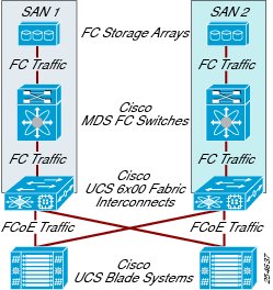
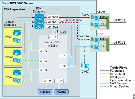
Fibre Channel storage arrays are attached to members of the Cisco MDS 9000 Family of switches. The Cisco MDS 9000 Family switches allow multiple arrays to talk to multiple hosts (servers) in much the same manner as an Ethernet switch would. The Cisco MDS 9000 Family switch connects to Fibre Channel uplinks on the Cisco UCS 6100 and 6200 Series Fabric Interconnects. Traffic is encapsulated by the Cisco fabric interconnects into FCoE frames and passed to the server's VICs, where it is converted back into Fibre Channel packets and presented on the vHBA (Figure 15).
Fibre Channel connections typically operate in active or standby mode. If SAN A is the primary array, SAN B is a mirror copy. In some cases, depending on the storage array vendor, the uplinks from Cisco MDS 9000 Family switch A and Cisco MDS 9000 Family switch B may point to the same array. However, a particular logical unit number (LUN) will show up on only one of the interfaces at a time. For traffic load balancing, the user should mix the LUN assignments across the two SANs.Fibre Channel Storage Network
Figure 15 Fibre Channel Storage Network
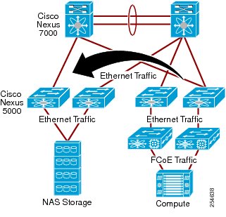
Network-Attached Storage
With network-attached storage, traffic originating from the NFS server is switched as Ethernet traffic to the storage array through the Cisco Nexus 5000 or 7000 Series Switches (Figure 16). The Cisco Nexus switches provide a universal platform for diverse data center needs, facilitate network consolidation, and enable a transparent transition from traditional to advanced technologies. As with Fibre Channel attached storage, the remote array is mapped to a local hypervisor storage pool, and the hypervisor provides virtual desktops with simulated local storage. Because this solution is Ethernet-based, storage is assigned to a separate storage VLAN. In most cases, the storage array is placed in the same VLAN. This approach alleviates the need for the hypervisor or desktop virtualization virtual machines to have multiple default routes, which can cause network problems.
Figure 16 Ethernet-based Storage Network
Data Center Networking
The data center network design follows the Cisco standard layered data center architecture, with access, aggregation, and core layers. The physical core and aggregation layers are collapsed within the Cisco Nexus 7000 Series Switches through the use of virtual device instances. This approach provides high levels of performance, scalability, and availability for the validation environment. To help ensure the most efficiency and security, the system makes extensive use of VLANs to separate traffic flows in the data center network.
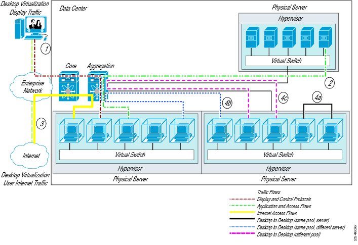
For virtual desktop traffic, as shown in Figure 17, the traffic flows include:
•
•
•
•
•
•
Figure 17 Virtual and Physical Traffic Flows in the Data Center Network
VLANs for the Virtualized Data Center
Figure 18 shows a server with a pair of interface cards installed and the logical connections made within the server. Each card presents itself to the server Fibre Channel HBAs and Ethernet NICs. When the hypervisor (VMware vSphere in the example in Figure 18) is installed, the Fibre Channel HBAs are mapped to vHBAs, which can be used for attaching remote storage. The Ethernet interfaces are mapped to the Cisco Nexus 1000V virtual switch. The Cisco Nexus 1000V treats these interfaces as uplink ports. These ports are usually configured as trunk ports and connected through EtherChannel for redundancy and load balancing.
Within the Cisco Nexus 1000V, several virtual Ethernet (vEth) interfaces are created. One is reserved for the kernel traffic (connection to VMware vCenter) and is put into a separate VLAN and assigned a unique IP address. A second vEth is reserved for VMware vMotion, and it also is placed in a separate VLAN and assigned a second unique IP address. Neither interface is seen by the virtual desktops. For security reasons, the virtual desktops do not have access to these VLANs. One final reserved vEth may be created if the VMware vSphere hypervisor data store is connected through Ethernet-based storage (NFS). The Ethernet-based storage traffic should also be isolated in its own VLAN.
Additional VLANs are created for the virtual desktops. IP addresses may be statically defined or acquired through Dynamic Host Configuration Protocol (DHCP). Address assignments and subnet masks need to be created according to the size of the virtual desktop pool. Virtual desktops can migrate only within the same pool (subnet, VLAN, and so on). For each virtual desktop, only a single vNIC needs to be created. Virtual desktops from different pools can run on the same physical server. The configuration for the trunk ports needs to include all possible VLANs, including those for the allowed virtual desktops. The Cisco Nexus 1000V creates an EtherChannel across the two CNA (NIC) interfaces, so loads on each interface should be monitored to help ensure that the appropriate load-balancing algorithm was selected.
The Cisco Integrated Management Controller (IMC) is forwarded internally to the Cisco UCS fabric interconnects. Cisco UCS Manager assigns and manages this interface. The IP address assigned to the Cisco IMC must be on the same subnet as Cisco UCS Manager. This address is used for remote keyboard, video, and mouse (KVM) devices and server maintenance.
The VMware VMkernel interface is used to communicate with VMware vCenter. The IP address should be assigned to a VLAN separate from the Cisco IMC interface. This VLAN should be routable to the VMware vCenter server's VLAN.
The VMware vMotion interface is used for virtual desktop mobility. It also should be assigned to a separate VLAN that is common to all the servers within the same virtual desktop pool. This network does not need to be extended beyond the access layer, because VMware vMotion is a nonroutable protocol. VMware vCenter will use the VMware vMotion interfaces on the servers (and the associated VLAN) for the traffic flow needed to migrate the virtual desktop. Because the virtual desktop's storage is maintained remotely, only the contents of the RAM (the CPU state) of the desktop are transmitted.
Figure 18 Data Center Connectivity (vSphere Example)
Table 6 List of Recommended VLANs for Deployment
Cisco UCS Manager
Cisco UCS blade server chassis, fabric interconnects, and blade server integrated management controller
Out-of-band management of all Cisco UCS components
This VLAN may be shared with other management VLANs.
vMgmt
Hypervisor
Management of all hypervisors
This VLAN is specific to a particular desktop virtualization pool; therefore, there may be separate VLANs for each pool.
vMigration
Hypervisor
Migration of virtual machines within the HVD pool
As with vMgmt, there may be several separate VLANs for each pool.
Cisco Nexus Control & Data
Cisco Nexus 1000V Series VEM and VSM
Cisco Nexus 1000V Series management
This VLAN is common to all physical servers that provide the distributed switch functionality. There may be more than one Cisco Nexus 1000V installed in a data center
VMData
Virtual machines and desktops
User's network access display protocol
Desktop virtualization machines should only need one interface. There should be one VLAN for each HVD pool.
VMProvision
Citrix Provisioning Server
Clean desktop to users at login
This VLAN is for traffic related to creating and provisioning virtual desktops from a single image on demand; this traffic should be kept separate from normal virtual machine traffic.
VMStorage
Hypervisor
Isolation for storage traffic
This VLAN is for Fibre Channel or IP-based storage
Data
HVD endpoint
Connection to the HVD virtual machine
The HVD data VLAN may be segregated from the legacy compute endpoint VLANs
Voice*
Unified communications endpoints
Provides unified communications access
Traditional voice VLAN
Virtualized Data Center Management
The solution design creates a separate IP network for management traffic with a dedicated IP subnet and VLAN. This approach enables remote-access, Simple Network Management Protocol (SNMP), syslog, and FTP traffic to be managed out of band. Separating traffic in this way helps ensure that end-user and administrative traffic flows do not compete for or interfere with available bandwidth. Remote access to a device will not be compromised when the device needs to be reset or provisioned. This practice also mitigates threats to network security and availability that could be introduced when end-user and administrative traffic share the same interface. Management and user traffic isolation is important in the data center, because desktop virtualization concentrates user traffic in an infrastructure traditionally used for server and management traffic loads.
Each management tool uses a specific set of protocols to communicate with devices. Table 7 provides an overview. Refer to the vendor documentation for a complete list of protocols and ports used by each tool. Make sure that these ports are open on all intermediary routers, switches, and firewalls.
Table 7 Management Tools
Modular Data Center Blocks
Cisco has partnered with key storage and virtualization partners to develop and deliver prepackaged, validated infrastructure solutions for data centers. These solutions provide computing, storage, server, management, and virtualization resources in an integrated and modular form. The Cisco Virtual Workspace Smart Solution architecture supports the use of these solutions as effective data center building blocks. These packages simplify planning, facilitate acquisition, speed deployment, and reduce risk. Cisco has partnered on the following solutions:
•
•
•
Virtualization Aware Network
The Cisco® Virtual Workspace network design uses Cisco best practices for deploying campus, branch-office, and data center network infrastructure. However, a Cisco Virtual Workspace network design also must consider virtual desktop display protocols, unified communications requirements, and changing traffic patterns to create a better user experience. Display protocol traffic may be optimized and secured for network transport. The network must provide high levels of availability, reliability, and security especially for virtual desktops and data center applications because a network failure impacts access to all applications.
This chapter, together with the Securing Cisco Virtual Workspace chapter, describes the design of a highly available and secure network for desktop virtualization.
This chapter addresses the following critical elements of a successful design, summarized in Figure 19:
•
•
•
•
•
Figure 19 Elements of a Desktop Virtualization Network
What's New in Release 2.7?
•
•
•
Cisco Network Deployment Models
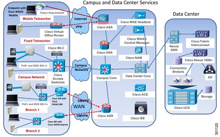
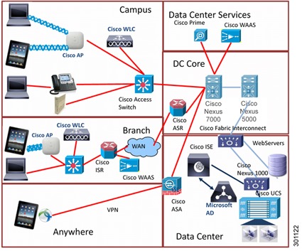
Figure 20 shows the three most common Cisco Virtual Workspace deployment models. Virtual desktop users can be on campus, in a branch office, or fixed or mobile teleworkers. The Cisco Virtual Workspace network is designed to help ensure that users enjoy the same high-quality experience, regardless of physical location. This section discusses Cisco Virtual Workspace design requirements for each scenario, and the main technologies used to meet these requirements.
Figure 20 Key Components for Enabling Virtual Workspace Networks
Campus
The campus network connects end users and devices in the corporate network with the data center and WAN. This section describes best practices for connecting endpoints to a first-hop switch, because this switch is where all the endpoint services are delivered in the campus network. For overall campus network design principles (from the first-hop switch to the data center edge), please refer to the Cisco Enterprise Campus 3.0 Architecture recommendations. The Cisco Virtual Workspace campus network provides a comprehensive set of services, such as:
•
•
•
•
•
To enable these services, Cisco Virtual Workspace endpoints within the campus network should be connected to a wiring closet switch such as a Cisco Catalyst® 4000, 3000, or 2000 Series Switch.
Automatic Port Provisioning
Auto Smartports enable the switch to dynamically provision Cisco Virtual Workspace clients by automatically configuring a port based on the device identification information obtained through the Cisco Discovery Protocol or MAC addresses. Smartport macros are pre-created, customizable configuration scripts based on Cisco best practices that allow administrators to easily set up common switch-port configurations. Auto Smartports help ensure consistent use of security, QoS, and high-availability policies.
With Auto Smartports, the macros are applied by the switch on the basis of end point credentials. The configuration is removed when the link to the end point is dropped or when the user session is terminated. Cisco VXC endpoints do not support Smart-ports based on dynamic macros. Cisco Virtual Workspace testing enabled the Auto Smartports feature to detect Cisco IP Phones and used static MAC address-based macros for Cisco VXC endpoints. The Cisco Catalyst 4500E and 3000-X switch platforms support both types of macros.
Static Smartports macros provide port configurations that can be manually applied on the basis of the device connected to the port. When a static macro is applied, the command-line interface (CLI) commands attached to the macro are added to the existing port configuration. These configurations are not removed during a link-down event on the port.
To use a static macro, configure a MAC address group with a MAC address operationally unique identifier (OUI)-based trigger. The first three octets of the MAC address identify the vendor and can be used to define the MAC address group trigger. Map the trigger to a built-in or user-defined macro, and the macro can be applied on an access switch globally or on an interface. This macro is applied when the Cisco VXC endpoint connecting to the switch meets the trigger condition defined earlier. If the connecting endpoint does not trigger the macro, the port is considered untrusted and can be placed in a guest VLAN by default. The user-defined macro file can be maintained in a remote server location, and all access switches in the network can consistently apply the same macro; this approach is the recommended deployment model for Cisco Virtual Workspace.
The procedure for manual configuration can be found at:
Securing Endpoint Access
Cisco Catalyst switches provide security and availability functions for Cisco Virtual Workspace endpoints, helping ensure that some traffic types are characterized and secured based on log-in characteristics. For example, contractors can use their own devices, with the contractor's virtual desktop accessed using a thin or thick client. When the contractor connects to the network, the contractor logs in using the username and password and is authenticated using IEEE 802.1x; the Cisco Catalyst switches map the user to a discrete contractor VLAN with access control lists (ACLs) that enable access to the Internet and connectivity to the contractor desktops only. The Cisco Catalyst 4500 E and 3000-X platforms provide IEEE 802.1x and port security features to provide endpoint-level security. The deployment and design details for these security features are discussed in Securing Virtual Workspace chapter of this guide.
Endpoint Location Tracking
The Network Mobility Services Protocol (NMSP) provides the capability to determine the physical location of a host in the network. It provides the capability to track assets for inventory and compliance purposes. Access switches, such as the Cisco Catalyst 4500E and 3000-X platforms, provide a wired location service feature and transmit location information for connected endpoints to the Cisco Mobility Services Engine (MSE). Cisco MSE is an appliance-based platform for delivering mobility services in a centralized and scalable way across wired and wireless networks.
In the case of a wireless connection, the access point tracks and transmits location information for its connected Cisco Virtual Workspace endpoints to the Cisco MSE through the Cisco Wireless Control System (WCS), shown in Figure 21. Cisco WCS is the management platform for location services and device tracking. It allows you to setup event notifications, and alarms based on location triggers. The actual location information for the switch and access point and the ports on the switch is configured in the switch or access point itself.
Figure 21 Location Tracking Topology
Device information such as the MAC address, IP address, serial number, unique device identifier (UDI), and model number can be obtained by the switch or the access point. Some of Cisco VXC and other supported endpoints do not support Cisco Discovery Protocol (CDP) and Link Layer Discovery (LLDP) Media Endpoint Discovery (MED). In that case, you should use Address Resolution Protocol (ARP) snooping to learn the IP address and MAC address of the endpoint on wired switches and the Wi-Fi endpoint registration sequence on wireless access points. For the Cisco VXC endpoint attached to an IP phone, the location tracking can be performed by using Cisco Discovery Protocol and LLDP-MED from the phone. Switches and access points also transmit state information such as device category (wired or wireless), time of attachment, and operational state (connected or disconnected). Cisco MSE holds the location database and, in this release of Cisco Virtual Workspace, a manually maintained list of MAC addresses tied to each enterprise client. All models of Cisco switches and Cisco access points support location services natively and can be used in Cisco Virtual Workspace. However in the Cisco Virtual Workspace design, only the Cisco Catalyst 4500E and 3000-X were validated.
The guidelines for configuring location tracking can be found at: http://www.cisco.com/en/US/docs/solutions/Enterprise/Data_Center/VXI/configuration/VXI_Config_Guide.pdf.
CLI commands for the sequence discussed here and other useful debugging information can be found at:
Detailed configuration steps and screen shots for location-based services, also called context-aware-services, can be found at:
http://www.cisco.com/en/US/partner/docs/wireless/mse/3350/7.0/CAS/configuration/guide/CAS_70.html
Wired and wireless endpoints can be looked up by IP address, partial IP address, MAC address, partial MAC address, or VLAN ID. Cisco WCS can be set up to serve notifications when certain conditions about endpoint location or status are met. The links listed in this section discuss these aspects of tracking. For a quick video overview of these functions, please see:
Campus - Access High -Availability and In-Service Software Upgrade
Cisco Virtual Workspace requires high availability of the network and reduced downtime during the planned software upgrades. Cisco Catalyst 4500E in a redundant configuration with dual supervisors provides high -availability and allows Cisco IOS® Software to be upgraded or modified while packet forwarding continues using the In-Service Software Upgrade (ISSU) feature. The ISSU feature allows a nondisruptive user experience during a planned upgrade or modification. The ISSU process with the Cisco Catalyst 4500E Supervisor Engine 7-E is reduced to a single-line command, and the traffic interruption is less than 10 milliseconds (ms). The Cisco Virtual Workspace session PoE and data plane stay up during the ISSU process. Access-switch high availability is provided by the Cisco Catalyst 4500 Series Switches modular chassis through ISSU. A detailed deployment guide can be found at
Branch-Office
Branch-office users may access their virtual desktops across bandwidth-constrained or untrusted WAN links and thus present a number of challenges.
Dynamic Multipoint VPNs in Cisco Virtual Workspace
In a Cisco Virtual Workspace system, virtual desktop traffic usually travels from the branch office to data center. Collaboration traffic may be peer to peer between branch offices. Both types of traffic may need to travel across untrusted WAN links. Because of these factors, a solution is needed that can dynamically create and tear down encrypted tunnels based on the traffic destination. Cisco Virtual Workspace recommends Dynamic Multipoint VPN (DMVPN) for this purpose. DMVPN provides both security and optimized route selection in distributed environments.
DMVPN routers use generic routing encapsulation (GRE) -based tunnel interfaces that support IP unicast, IP multicast, and broadcast traffic as well as dynamic routing protocols such as Enhanced Interior Gateway Routing Protocol (EIGRP). After the initial spoke-to-hub or branch-office-to-campus tunnel is active, dynamic spoke-to-spoke or branch-office-to-branch-office tunnels are created, depending on traffic-flow requirements. DMVPN uses Next-Hop Resolution Protocol (NHRP) to find other spokes based on IP destination. The branch-office-to-branch-office tunnels are encrypted using IP Security (IPsec). Idle connections between branch offices are timed-out. Internet Security Association and Key Management Protocol (ISAKMP) provides dead-peer detection (DPD) so that unused or orphaned tunnels do not remain active. IPsec tunneling is also required when DMVPN hubs are behind firewalls implementing Network Address Translation (NAT). Since the tunnels are created behind the physical interface, branch-office routers configured for DMVPN can use the Dynamic Host Configuration Protocol (DHCP) address provided by the service provider. The DMVPN hub, however, must have a static IP address so that all branch-office routers can be created in the initial spoke-to-hub tunnel.
Use Cisco Integrated Services Routers Generation Two (ISR G2) for the spoke (branch office) and use Cisco Aggregation Services Routers (ASRs) and Cisco 7200 Series Routers for the hub (head-end). All the routers must have security plus licensing for Cisco IOS Software to enable DMVPN functions.
WAN optimization is also used to help ensure a high-quality user experience. WAN optimization and DMVPN can be deployed together successfully, but some configuration best practices need to be followed. An excellent resource for DMVPN and Cisco WAN deployments in general is located at
http://www.cisco.com/en/US/solutions/collateral/ns340/ns414/ns742/ns982/c07-610746-02_wanDeploy.pdf.
All other main resources specific to Cisco DMVPN are located at
http://www.cisco.com/en/US/products/ps6658/index.html
Cisco Wide Area Application Services
Cisco WAAS enables WAN optimization to address the challenges of delivering virtual desktops. Refer to the WAN Optimization for Cisco Virtual Workspace section of this chapter for details.
Endpoint Access Services in the Branch Office
Campus access features such as PoE+, location tracking, and Auto Smartport provisioning previously discussed are also supported in the branch-office environment and are recommended in Cisco Virtual Workspace deployments.
Teleworker
The Cisco Virtual Workspace system supports both fixed and mobile teleworkers. Both types will likely access virtual desktops in the same data center. The only difference is the location from which the remote user is connecting.
A fixed teleworker uses a fixed network device, which provides secure connection and comprehensive network services to full- and part-time home-office workers, mobile contractors, and executives. A fixed teleworker in a Virtual Workspace environment can establish a secure connection using either of two methods:
•
•
By providing extensible network services that include data, voice, video, and applications, the Cisco Virtual Office creates a comprehensive office environment for employees. The Cisco Virtual Office solution consists of the following components:
•
•
•
•
A network enabled for Cisco Virtual Workspace provides additional benefits to the fixed teleworker using the Cisco Virtual Office solution. These enhancements provide the capability to deploy Cisco VXC behind the Cisco Virtual Office router. The end user can now access a virtual desktop through a secure VPN tunnel between the Cisco Virtual Office router and the corporate edge router. The virtual desktop can have a Cisco Unified Communications client installed, enabling the user to control an IP desk phone. More information about the Cisco Virtual Office solution can be found at http://www.cisco.com/en/US/netsol/ns855/index.html.
Cisco Virtual Workspace mobile teleworkers connect to virtual desktops securely from any endpoint that supports a Cisco AnyConnect® Secure Mobility client. Mobile teleworkers are typically in unsecure network locations. One of the advantages of Cisco Virtual Workspace is that the data stays secure, even if the endpoint is stolen, damaged, or lost. Teleworker secure connections are discussed in detail in the Securing Cisco Virtual Workspace chapter.
Cisco WAAS Mobile optimizes virtual desktop traffic over these secure connections to provide a better user experience. The Cisco WAAS Mobile client is installed on the endpoint device, connecting through a VPN or in a home-office router (Cisco Virtual Office router) to the Cisco Virtual Workspace data center. The Cisco WAAS Mobile client pairs with a Cisco WAAS Mobile server positioned behind the VPN. Note that the Cisco WAAS Mobile server is not the same as a Cisco WAAS headend appliance and so cannot pair with the Cisco Wide Area Virtualization Engine (WAVE), Cisco WAAS Express, or Cisco WAAS on Cisco Services-Ready Engine (SRE) products. Cisco WAAS Mobile functions are turned off when a teleworker endpoint is in a campus or branch-office environment, to allow more full-featured WAN optimization. Cisco WAAS Mobile deployments are managed by Cisco WAAS Mobile Manager, which provides the capability to monitor performance and measure return on investment (ROI).
For more information about Cisco WAAS Mobile, see:
http://www.cisco.com/en/US/prod/collateral/contnetw/ps5680/ps6870/data_sheet_cisco_wide_area_application_services_mobile.html
Figure 22 shows the mobile teleworker with a thick client connecting to a hosted virtual desktop from an unsecure location using a secure connection.
•
•
•
•
Figure 22 Teleworker with Thick Client
Cisco Virtual Workspace Data Center Edge
Desktop virtualization relies on always-on network connectivity to the data center. Network availability has become a critical part for every network design. Cisco provides high-availability network design guidance focused on specific areas of the enterprise network, such as the data center, campus, branch office and WAN, and Internet edge. Hierarchical network design is a common strategy for designing a network for high availability. For high-availability network design guidance when building a network enabled for Cisco Virtual Workspace, see http://www.cisco.com/en/US/docs/app_ntwk_services/data_center_app_services/ace_appliances/vA1_7_/configuration/device_manager/guide/UG_ha.html.
Load Balancing, SSL Offloading and Cisco Virtual Workspace Health Monitoring
The connection brokers used to offer virtual desktops in a virtual desktop infrastructure (VDI) environment need to be load balanced. Load balancing has been validated with Cisco Application Control Engine (ACE). For load balancing and SSL offloading, the Cisco ACE is deployed at the aggregation layer in the data center using one-arm mode. In one-arm mode, the Cisco ACE is configured with a single VLAN that handles both client requests and server responses. Routed and bridged Cisco ACE deployments also work in this design. For one-arm mode, client-source NAT or policy-based routing (PBR) needs to be configured. The Cisco ACE then uses NAT to send the requests to the real servers. Server responses return through the Cisco ACE rather than directly to the original clients. This topology is convenient, because the Cisco ACE can be almost anywhere on the network, but its reliance on NAT makes it impractical in some situations. If you are using routed or bridging mode, confirm that there is sufficient bandwidth for all user display connections. In a one-arm topology, the Cisco ACE is connected to the real servers' connection broker through an independent router and acts as neither a switch nor a router for the real servers. Clients send requests to the virtual IP address on the Cisco ACE.
The recommended approach is to use two Cisco ACE appliances. Either the Cisco ACE Module or 4710 Appliance can be used. When deploying the Cisco ACE Module, technologies such as the Cisco Catalyst 6500 Virtual Switching System (VSS) 1440 with multichassis EtherChannel can help improve network resiliency by delivering network convergence in less than a second in the event of failure. Cisco ACE 4710 Appliances connect to the aggregation layer using a PortChannel and are enabled for high availability. The Cisco ACE Module or 4710 Appliance load-balances virtual desktop requests to the connection broker while providing session persistence. The main features implemented on the Cisco ACE for the Cisco Virtual Workspace system are:
•
•
•
The Cisco ACE periodically checks the health of the connection broker. Using the probe information, Cisco ACE determines if the connection broker can service the user's request with the best performance and availability.
To access a virtual desktop, the user connects to a virtual IP address configured on the Cisco ACE. Then the Cisco ACE forwards the request from the user to the connection broker. Cisco ACE supports several session persistence mechanisms between the client and the connection broker so that a particular client session is always directed to the same server. The Cisco ACE is configured to perform session persistence based on the client IP address. If proxy servers are used, Cisco recommends enabling JSESSIONID cookie persistence.
When deploying a Cisco ACE with connection brokers, Cisco recommends either tunnel or direct mode, or a combination of the two methods.
•
•
Figure 23 shows the deployment of the Cisco ACE 4710 Appliance using direct mode. The Cisco ACE 4710 provides load balancing only for the connection broker. After the connection broker has assigned the user a virtual desktop, the display protocol bypasses the Cisco ACE 4710. The Cisco ACE is configured in one-arm mode. One-arm mode is preferred in a network enabled for Cisco Virtual Workspace. Because the display protocol is between the end user and the virtual desktop, Cisco ACE does not need to be in the middle of the transaction, which saves resources on the Cisco ACE for load balancing incoming end-user requests for an available desktop from the connection broker. Because Cisco ACE is deployed in one-arm mode, you need to configure Source NAT.
Figure 23 Cisco ACE Deployment in the Network
Table 8 provides detailed configurations for enhancing DV server availability. Cisco Virtual Workspace validated the ACE virtualized device environment by creating a virtual context named VMware DV load balancing. The virtualized device environment provided by the Cisco ACE is divided into objects called contexts. Each context behaves like an independent Cisco ACE load balancer with its own policies, interfaces, domains, server farms, real servers, and administrators. Each context also has its own management. When Cisco ACE is deployed, the Admin context is used for managing and provisioning other virtual contexts.
Table 8 DV Server Configurations
Admin context configuration
Allow only Telnet, SSH, Simple Network Management Protocol (SNMP), HTTP, HTTPS, or Internet Control Message Protocol (ICMP) traffic.
The Admin context is used to configure:
•
•
•
•
Configuring Virtual Contexts[http://www.cisco.com/en/US/docs/app_ntwk_services/data_center_app_services/ace_appliances/vA1_7_/configuration/device_manager/guide/UG_confg.html]
One-arm mode configuration
One-arm mode is recommended for load balancing the connection broker.
Source NAT is required.
Configuring One-Arm Mode [http://docwiki.cisco.com/wiki/Basic_Load_Balancing_Using_One_Arm_Mode_with_Source_NAT_on_the_Cisco_Application_Control_Engine_Configuration_Example]
Virtual context configuration for Citrix desktop virtualization
Use Citrix's Independent Computing Architecture (ICA).
To load-balance the ICA connection, create a Layer 4 class map.
Configuring Virtual Server Properties [http://www.cisco.com/en/US/docs/app_ntwk_services/data_center_app_services/ace_appliances/vA1_7_/configuration/device_manager/guide/UG_lb.html#wp1044682]
Configuration of session persistence
Session persistence is based on the source IP address.
IP Address Stickiness [http://www.cisco.com/en/US/docs/app_ntwk_services/data_center_app_services/ace_appliances/vA1_7_/configuration/device_manager/guide/UG_lb.html#wp1062118]
Configuration of health monitoring
Use HTTP probe with regular expression (RegEx) checking.
Use a RegEx statement in HTTP: Probeexpect regex ?Citrix?.
Configuring Health Monitoring for Real Servers [http://www.cisco.com/en/US/docs/app_ntwk_services/data_center_app_services/ace_appliances/vA1_7_/configuration/device_manager/guide/UG_lb.html#wp1045366]
Configuration of the load-balancing algorithm
Use the Least-Loaded algorithm.
Set the least number of connections in Serverpredictor leastconns.
Load-Balancing Predictors [http://www.cisco.com/en/US/docs/app_ntwk_services/data_center_app_services/ace_appliances/vA1_7_/configuration/device_manager/guide/UG_lb.html#wp1045366]
Configuration of source NAT
Source NAT is needed so the connection does not bypass Cisco ACE when responding to the end user.
Use the virtual address as the NAT address.
Cisco ACE NAT Configuration [http://docwiki.cisco.com/wiki/Basic_Load_Balancing_Using_One_Arm_Mode_with_Source_NAT_on_the_Cisco_Application_Control_Engine_Configuration_Example]
VPN Termination
Many IT departments use VPN solutions to provide secure connections to end users accessing virtual desktops from branch offices or teleworker locations. With solutions such as the Cisco ASA appliances and the Cisco AnyConnect Secure Mobility Client, end users can connect to their virtual desktops through secure tunnels.
The Cisco ASA 5500 Series Adaptive Security Appliance is a purpose-built platform that combines best-in-class security and VPN services. The Cisco ASA is a VPN concentrator and a firewall and is the first point in the data center or campus edge at which all traffic is received. All VPN tunnels from VPN clients such as Cisco AnyConnect or IPsec-enabled Cisco 800 Series Routers terminate here. Additional network security concerns and detailed information regarding the Cisco ASA appliances with the Cisco AnyConnect Secure Mobility Client are discussed in the Securing Cisco Virtual Workspace chapter.
Many IT departments use VPN solutions to provide secure connections to end users accessing virtual desktops from branch offices or teleworker locations. With solutions such as the Cisco ASA appliances and the Cisco AnyConnect Secure Mobility Client, end users can connect to their virtual desktops through secure tunnels.
The Cisco ASA 5500 Series Adaptive Security Appliance is a purpose-built platform that combines best-in-class security and VPN services. The Cisco ASA is a VPN concentrator and a firewall and is the first point in the data center or campus edge at which all traffic is received. All VPN tunnels from VPN clients such as Cisco AnyConnect or IPsec-enabled Cisco 800 Series Routers terminate here. Additional network security concerns and detailed information regarding the Cisco ASA appliances with the Cisco AnyConnect Secure Mobility Client are discussed in the Securing Virtual Workspace chapter.
Cisco Trustsec for Cisco Virtual Workspace (VXI) Smart Solution
Cisco Trustsec is a security solution to provide scalable secure architecture to enterprise networks built on existing identity based access layer security. Cisco Trustsec will build a network of mutually trusted network devices and strengthen the security of the enterprise networks. Cisco Identity Service Engine (ISE) is a component of Cisco Trustsec architecture which can provide contextual based access policy enforcement. Cisco Trustsec provides many enhancements to standard identity based access policy enforcement model including Security Group Access (SGA). After a user is authenticated, the resources access policy for authorization can be enforced using the SGA mechanism which is much more scalable than other authorization mechanisms. SGA allow capturing the identity of users and tagging each data packet called Security Group Tagging (SGT). If the network device is not capable of tagging the packet with SGT then the Trustsec solution will use Security Group Tag Exchange Protocol (SXP) to communicate the security tag to the next policy enforcement point. Once the SGT is inserted at the ingress of a data packet, the SGT can be used to enforce the access policy. The details of the Cisco Trustsec solution and its advantages can be found at: http://www.cisco.com/go/trustsec.
Cisco Virtual Workspace recommends using SGT for server segmentation and different access levels enforcement. The recommended access levels are Managed User/Managed Asset (Full Access), Managed User/Non-Managed Asset, Contractor, and Guest (Internet). For each access level a separate virtual desktop pool has to be created. Also the policy has to be enforced at multiple points in a Cisco Virtual Workspace environment and the recommended way to do this is by Security Group Access Lists (SGACL) or Security Group Firewalling (SGFW).
In Cisco Virtual Workspace deployments with Cisco Nexus 1000v switch, the SGT mappings to the servers can be provisioned in Cisco Nexus 1000v and send to the policy enforcement points like Cisco Nexus 7000 and Cisco ASA over SXP. The deployment details of the server segmentation using SGACL and SGFW can be found at the Trustsec Server Segmentation how-to guide at http://www.cisco.com/go/trustsec.
Bring-Your-Own-Device (BYOD)
With the proliferation of smart mobile devices and the trend of Bring-Your-Own-Device (BYOD), enterprises are facing a challenge to provide employees secure access to corporate resources on their personal devices. While BYOD has many advantages like increased work-force mobility and productivity, it poses a lot of challenges in supporting the various platforms and ensuring security of the corporate resources. Cisco BYOD Smart Solution 1.0 is a smart solution that allows users to connect, register and provision their personal devices for corporate use and for the access to the corporate network in a secure way. Deploying Cisco BYOD Smart Solution to access Cisco Virtual Workspace will allow the mobile device users to access virtual desktops and enable the enterprise to offer a unified workspace to the employees with reduced cost and increased productivity.
The fundamental building blocks for providing a BYOD solution are:
•
•
•
•
The Cisco BYOD smart solution details can be found at http://www.cisco.com/go/byod.
Cisco Virtual Workspace virtual desktops can be delivered to the BYOD device as part of the workspace delivery when the Cisco BYOD components are added to the Cisco Virtual Workspace infrastructure. A typical Cisco Virtual Workspace deployment with BYOD components is depicted Figure 24 below.
Figure 24 Bring-Your-Own-Device
The constructs and mechanisms defined for workspace delivery and contextual based policy enforcement should be adapted from the Cisco BYOD smart solution for the delivery of Cisco Virtual Workspace to BYOD devices. The Microsoft Active Directory (AD) used in Cisco Virtual Workspace infrastructure for user identity should be added as an identity store in Cisco ISE so that once the user gets the access through the Cisco ISE, a desired access policy can be downloaded to the Wireless LAN Controller (WLC). Cisco Virtual Workspace smart solution recommends provisioning Cisco ISE to provide an authorization policy for the mobile devices just to have the access to Virtual Workspace infrastructure and Internet. Also every WLC deployed in campus and remote-sites should be provisioned to gather authorization policy from Cisco ISE as the BYOD device authenticates with that controller. Also Cisco ISE should be provisioned with authorization policies to deny access for the undesired BYOD devices.
The remote access from the BYOD device can be provisioned as outlined in the remote access section of the Cisco BYOD smart solution guide.
The collaboration services can be provided through Cisco Jabber application and the details of the architecture and design guidelines can be found at the Collaboration chapter of this solution guide.
WAN Optimization for Virtual Workspace
The primary challenge in delivering HVD traffic across the WAN is helping ensure that performance is sufficient to meet end-user expectations. The Cisco Virtual Workspace system is designed to mitigate the effects of limited bandwidth, latency, and packet loss often associated with desktop virtualization and WANs.
Cisco WAAS optimizes WAN links through the use of intelligent caching, compression, and protocol optimization. When end users access the virtual desktops through the connection broker, Cisco WAAS compresses the response and then efficiently passes it across the WAN with little bandwidth use and high speed. Commonly used information is cached at the Cisco WAAS solution in the branch office and at the data center, which significantly reduces the burden on the servers and the WAN. Cisco WAAS accomplishes all WAN optimization functions using advanced compression using Data Redundancy Elimination (DRE), Lempel-Ziv (LZ) compression, and Transport Flow Optimization (TFO), which improves throughput and reliability for clients and servers in WAN environments. TFO optimizes TCP-based display protocols even if the display protocol traffic is encrypted and compressed. Some of these algorithms may not apply to optimization of the display protocols, but they are still useful in Cisco Virtual Workspace for the traffic flowing outside display protocols.
Cisco WAAS also enhances the performance and accelerates the operation of a broad range of chatty application protocols, such as Citrix's ICA, Common Internet File System (CIFS), HTTP, SSL, and Messaging Application Programming Interface (MAPI) using application-specific accelerators (also called application optimizers [AO]) over the WAN. This optimization provides additional bandwidth for desktop virtualization and multimedia traffic.
Optimization of desktop virtualization protocols, including Citrix HDX and ICA and Remote Desktop Protocol (RDP) is achieved by applying DRE, LZ, and TFO techniques. Note that Cisco WAAS works only with TCP transport as of now and does not support UDP transport. Thus, protocols that use UDP transport cannot benefit from using Cisco WAAS. However, in combination with optimization that reduces the bandwidth consumed by chatty protocols, even UDP traffic can see noticeable benefits.
Cisco WAAS provides a holistic approach to support for a variety of print strategies, including centralized network printing through a print server, which can dramatically improve printing performance and reduce WAN data by using print-specific optimizations. Cisco WAAS provides print servers locally to branch-office users by running Microsoft Windows print services. When combined with USB redirection, Cisco WAAS offers optimization of the printing traffic redirected to locally attached peripherals (such as USB-connected printers) at the branch-office client device by reducing bandwidth utilization and mitigating WAN latency. Deploying Cisco WAAS on existing branch-office WAN connections also helps save bandwidth and allows both Cisco Virtual Workspace and other traffic to be optimized.
Table 9 lists Cisco WAAS technologies applicable to various types of applications and traffic types seen in a Cisco Virtual Workspace system.
Table 9 Traffic Types
Citrix introduced HDX and MMR to address interactive multimedia problems. Citrix HDX technology provides network and performance optimizations to deliver the best user experience over any network. Citrix HDX and MMR are optional features providing additional protocol optimization for interactive multimedia delivery in the display protocol. Cisco Virtual Workspace recommends that these features be enabled, if they are available, along with Cisco WAAS.
Native ICA Optimization
Cisco Virtual Workspace recommends enabling Cisco WAAS with Citrix Independent Computing Architecture (ICA) optimization because doing so can increase the number of users on a WAN link by a factor of two to three, achieving significant savings in bandwidth consumption and helping to fully use the link. ICA AO disables native compression provided by ICA and then uses DRE and LZ compression to compress the session. By performing the compression in the network, Cisco WAAS can eliminate data redundancy for a single session or across multiple sessions. To apply DRE compression, the ICA session must be decrypted. Cisco WAAS decrypts the session before applying compression on the sending Cisco WAAS appliance and then re-encrypts the session on the receiving Cisco WAAS appliance before forwarding the session to the endpoint or desktop.
Cisco WAAS operations are transparent to the endpoints, and no special endpoint configuration is required. Cisco WAAS ICA AO is available in Cisco WAAS Software Release 4.5.1 and later, and it provides ICA optimization for Citrix XenDesktop and XenApp using three types RC5 encryption: 40 bit, 56 bit, and 128 bit keys. ICA AO supports optimization of ICA with session reliability enabled using Common Gateway Protocol (CGP). In such a case, TCP port 2598 is used for the primary connection. Cisco WAAS 5.1 the DRE and LZ compression are tuned for smaller packets and so the compressions of ICA/CGP streams are improved.
Native ICA optimization operations require more CPU resources and introduce a small amount of latency. However, scalability and latency depend on the type of native ICA encryption used, traffic work load, and number of ICA sessions passing through the Cisco WAAS. Refer to the Cisco Virtual Workspace Performance and Capacity Validation Results Guide for Citrix [http://www.cisco.com/en/US/docs/solutions/Enterprise/Data_Center/VXI/CVD/VXI_PCV_C.pdf] document for network characterization test results for Cisco WAAS and ICA AO in a Cisco Virtual Workspace deployment.
Figure 25 provides an overview of Cisco WAAS ICA AO.
Figure 25 Cisco WAAS ICA Application Optimization
•
•
Citrix Multi-stream ICA (HDX Multi-Stream)
Citrix introduced Multi-stream ICA (also known as HDX Multi-Stream) with Citrix XenDesktop 5.6, XenApp 6.5 and Receiver 13.0 client. In single stream ICA, all the content between host and client is multiplexed into 64 virtual channels contained in the same Citrix ICA TCP stream with port 1494 or 2598 with Citrix Common Gateway Protocol (CGP) when using session reliability. Although the virtual channels in the TCP stream were prioritized based on content, the content or the virtual channels were opaque to the network and so network administrators were unable to provide the required differentiated QoS treatment for real-time traffic.
Multi-stream ICA offloads certain virtual channels to separate TCP or UDP sessions. This change results in multiple TCP and one UDP stream to transport the desktop session. Currently multi-stream ICA supports up to four independent TCP streams and one UDP stream per virtual desktop. Figure 26 shows the separate traffic streams for a multi-stream ICA session.
Figure 26 Citrix Multi-stream ICA
Multiple virtual channels from the 64 virtual channels are grouped by priority and transmitted to the appropriate TCP or UDP stream and the following table outlines this mapping.
Table 10 Multi-stream ICA Traffic Types
Current version of Citrix XenDesktop and XenApp has single-stream ICA as default. To enable multi-stream ICA in Citrix XenDesktop or Citrix XenApp, the Citrix Multi-stream policy in the Machine and User settings should be enabled in the administration console in Citrix XenDesktop Desktop Studio or Citrix XenApp AppCenter (formerly Citrix Delivery Services Console) respectively. There are no default ports configured for the various TCP streams. The primary (TCP: Interactive) stream's CGP port is pre-configured and the rest of the three TCP streams ports has to be configured. Also the priorities for each of these streams should be configured. The primary stream will be the high-priority stream. The other three available priorities are very high, medium and low. Two streams cannot have same priority and if a priority is not used the corresponding port should be configured as 0. The UDP stream uses default port of 16500-16509.
In Citrix XenDektop Multi-port policy definition under Machine Settings is used to configure custom ports and priorities. In Citrix XenApp the Multi-port policy definition under Computer Settings is used. If custom ports are not defined, the traffic will use the primary port. If multi-stream is enabled but session reliability (port 2598) is turned off, all traffic will default to single-stream on port 1494. After enabling the Citrix multi-stream and the custom port configuration, the Citrix XenDesktop or XenApp must be restarted for the policies to take effect.
Multi-stream ICA eases application of network QoS to the various HDX traffic types including interactive media. The Cisco Virtual Workspace recommended QoS guidelines can be found in the QoS section of this chapter. In Cisco WAAS 5.1 Citrix MSI can be enabled or disabled using CLI or WAAS Central Manager. The ICA/CGP ports are dynamically detected and the rules are set to intercept the traffic and so there is no additional port configuration required in Cisco WAAS. Also by default a QoS DSCP marking will be in effect for Citrix multi-stream ICA streams and the values are re-configurable. So the application of QoS does not require a manual configuration in Cisco WAAS 5.1.
The Server will determine the establishment of multi-stream ICA connection by capability negotiation with the client or endpoint. If server is enabled for multi-stream ICA then the capability negotiation starts and even if the intermediate WAAS devices are disabled for multi-stream ICA if the endpoint is capable of multi-stream ICA, the multi-stream ICA streams will be established. If intermediate WAAS devices are multi-stream ICA enabled and the endpoint and server are capable of multi-stream ICA, even the multi-stream ICA is not enabled at server the multi-stream ICA streams are established.
Once the ports for multi-stream ICA are configured by the data center administrator, those ports has to be provisioned in Firewalls and Cisco Virtual Office by the network administrator to allow the additional traffic flowing between the user endpoints and the virtual desktops.
Currently the Citrix multi-stream ICA is supported on Microsoft Windows based endpoints with Citrix Receiver application or online plugin only.
Application-Aware DRE
In Cisco Virtual Workspace, the optimization over the WAN using application-aware DRE enhances the performance and scalability of the Cisco WAAS appliance, and there by the user experience. Advanced compression using context-aware DRE reduces the use of disk space and memory. This feature is available in Cisco WAAS Release 4.4 and later. Context-aware DRE supports two features: unidirectional DRE and single-instance data. These two features can greatly benefit the optimization of desktop session traffic that is unidirectional and can be optimized by Cisco WAAS.
Unidirectional DRE eliminates caching of unneeded data on the sending-side Cisco WAAS. For specific traffic, cache data is maintained only on the receiving-side Cisco WAAS when it is needed for decompression. The sending-side Cisco WAAS appliance does not keep this data because it is unlikely that the same data will flow in the reverse direction. This feature provides benefits to traffic that are asymmetrical, such as desktop session traffic. If the same data flows in the reverse direction, this data will not be optimized on the first transmission, but it will be optimized on subsequent transmissions. For asymmetrical traffic, this event is unlikely and should not affect performance. Traffic classification indicates to Cisco WAAS which traffic requires unidirectional caching and which requires bidirectional caching.
Single-instance data further improves caching efficiency by eliminating multiple copies of the same data for multiple connections across multiple branch offices. This feature reduces memory and disk space use, resulting in greater scalability and performance of the Cisco WAAS appliance. It allows Cisco WAAS to optimize data across user sessions, and it benefits scenarios in which the same desktop session data is being transmitted to multiple users (as in an audio or video stream, for example). This feature demonstrates the advantage that Cisco Virtual Workspace has in performing optimization in the network (by offloading the task from the endpoints and servers). This feature is enabled with both unidirectional and bidirectional DRE.
Deploying Cisco WAAS
Because Cisco WAAS is transparent in the network, some form of network interception is required to redirect relevant traffic types to the Cisco Wide Area Application Engine (WAE). Cisco WAAS supports many methods of network interception. The following methods are recommended with Cisco Virtual Workspace.
•
•
•
•
In the sample branch-office setup shown in Figure 27, the Cisco WAE appliance is connected to a local router, typically a Cisco Integrated Services Router (ISR), and in the data center Cisco WAAS is connected to a data center WAN edge router, typically a Cisco ASR. The branch-office router intercepts the traffic from Cisco VXC and other supported endpoints and sends it to the attached Cisco WAE, which after optimization sends it out the data center WAN edge router. The data center WAN edge router intercepts the traffic and sends it to the Cisco WAAS core for optimization, from which the traffic reaches the data center.
Figure 27 Cisco WAAS Deployment in the Branch Network
Cisco WAAS Form Factors
Multiple form factors for Cisco WAAS are available for deployment and are listed in Table 11. Network designers can select any form factor independently from an interoperability perspective, unless noted otherwise. All the Cisco WAAS models will work with the data center or campus Cisco WAAS WAE headend appliance, and the choice of branch-office or data center equipment depends on the scale needed and the version of software chosen. Detailed Cisco WAAS sizing guidelines can be found at: http://tools.cisco.com/WAAS/sizing
Table 11 Cisco WAAS Form Factor
Note
Cisco WAAS Central Manager
Cisco WAAS requires a central manager to manage the Cisco WAAS solution from a central point. The Cisco WAAS Central Manager resides on a Cisco WAE appliance. When the administrator applies configuration or policy changes to a Cisco WAE device or a group of Cisco WAE devices, the Cisco WAAS Central Manager automatically propagates the changes to each of the managed Cisco WAE devices. Each Cisco WAE device can be configured either as an application accelerator or a central manager. The best practice is to deploy both a primary and a standby central manager.
The Cisco WAAS ICA AO feature and context-aware DRE feature can be enabled and disabled from the Cisco WAAS Central Manager GUI or Cisco WAAS CLI. A number of monitoring and reporting capabilities are also available using the Cisco WAAS Central Manager. Important measurements for ICA include ICA bandwidth optimization, ICA compression over time, ICA optimized traffic over time, and ICA optimized connections over time.
Configuring Cisco WAAS in a Cisco Virtual Workspace Environment
Table 12 provides the configuration information needed to configure Cisco WAAS on a Cisco Virtual Workspace network.
Table 12 Cisco WAAS Configuration Information
Configuring Traffic Interception for Cisco WAAS Using WCCP
WCCP, as discussed earlier in this chapter, is used to configure the router to intercept all "interesting" traffic and forward it to Cisco WAAS. WCCP services 61 and 62 direct the router to reroute traffic from the interface to the WCCP group. Service 61 redirects ingress traffic, and service 62 redirects egress traffic. Services 61 and 62 are both needed to redirect bidirectional traffic flow.
You should exclude the Cisco WAE subnet from interception because this configuration uses a single interface to intercept incoming and outgoing packets. The interception exclusion is required because the router does not differentiate between traffic from the Cisco WAE for the client or server. Traffic from the Cisco WAE should not be redirected again by the router because doing so will create a loop.
Configure WCCP interception service 61 on the ingress interface and service 62 on the egress interface. All ingress and egress packets from the interface are forwarded to the Cisco WAE for optimization.
For more information, please read the Cisco WAAS section in the WAN deployment guide at http://www.cisco.com/en/US/docs/solutions/Enterprise/Borderless_Networks/Smart_Business_Architecture/February2012/SBA_Mid_DC_DataCenterDeploymentGuide-February2012.pdf.
Cisco WAAS appliances and Cisco vWAAS are expected by design to use the entire available RAM on the device or virtual machine. This condition is normal, and you should configure the low-memory alert with a higher threshold value to avoid unnecessary messages.
Cisco VSG and vWAAS are both virtual appliances that require a Cisco Nexus® 1000V Series Switch to function. Both these virtual appliances need to intercept traffic on the Cisco Nexus 1000V Series Switch and are not simultaneously supported as of this writing. As a workaround, if Cisco VSG is installed in the data center, then the Cisco WAAS appliance form factor can be used. Cisco WAAS appliances in the data center typically intercept traffic at the data center edge and do not require the Cisco Nexus 1000V Series for operation.
When Cisco vWAAS is used in the data center, the traffic needs to pass through the Cisco ASA at the data center edge. To allow Cisco ASA Software to recognize, permit, and secure traffic optimized by Cisco WAAS, a new CLI is provided. The new CLI should be enabled as part of the class modular policy framework (MPF) to facilitate Cisco ASA Software interoperability with Cisco WAAS.
Virtual Machine-Based Network Optimization: Cisco vWAAS
Cisco vWAAS is a virtual appliance that accelerates business applications delivered from private and virtual private clouds. Cisco vWAAS runs on Cisco Unified Computing System™ (Cisco UCS®) servers and the VMware vSphere hypervisor, using policy-based configuration in the Cisco Nexus 1000V switch. Cisco vWAAS can be associated with application server virtual machines as these are instantiated or moved. With Cisco vWAAS, cloud providers can rapidly provision WAN optimization services with little to no configuration or disruption (Figure 28).
Figure 28 Cisco vWAAS
Cisco vWAAS supports two deployment options:
•
•
The WAN edge is the traditional location for WAN traffic interception to be optimized. The out-of-path model uses WCCP to intercept traffic. In this model, the hypervisor hosts with Cisco vWAAS virtual machines connect to WCCP-enabled switches or routers. Multiple Cisco vWAAS virtual machines can operate in a cluster, optimizing all traffic intercepted by the router. The Cisco vWAAS virtual machines can be spread across single or multiple servers, and both physical and virtual Cisco vWAAS appliances can be mixed in a cluster.
In the deep data center deployment model, you should place Cisco vWAAS virtual machines next to server virtual machines in the same hypervisor host. Using the policy-based virtual services of the Cisco Nexus 1000V Series Switch, Cisco vWAAS can be deployed on a per-application or per-server-group basis. vPath interception in the Cisco Nexus 1000V Series intercepts all traffic to and from these servers and forwards it to the Cisco vWAAS virtual machine for optimization.
Cisco vWAAS requires storage access to store the DRE byte cache and the CIFS cache. In the data center, it supports either direct-attached storage or remote shared storage in a SAN. Cisco recommends the use of the SAN option to enable advanced hypervisor features (such as VMware vMotion, Storage vMotion, and High Availability, when the VMware Hypervisor is used).
WAN Stability and Path Optimization
In a Cisco Virtual Workspace deployment, the availability and efficiency of HVDs can be affected by suboptimal routing and path selection. Cisco recommends using Performance Routing (PfR) to reduce the effects of network instability and link quality changes. PfR improves application performance by selecting the best path across the WAN. PfR uses network metrics such as application reachability, delay, loss, and jitter to help select the best path based on application needs. It measures the network performance and dynamically reroutes the traffic when the metrics do not meet requirements. PfR thus provides path optimization and advanced load balancing for Cisco Virtual Workspace traffic over the WAN. PfR and Cisco WAAS provide different forms of WAN optimization, and when used together they can complement each other to provide a superior user experience.
PfR has two logical components: a master controller and a border router. The master controller acts as a central processor and data collection point for PfR and runs on the router or in standalone mode. The master controller gathers network metrics from all the border routers and determines whether traffic classes adhere to configured policies. On the basis of this determination, the master controller can instruct the border router to stay on the current WAN link or change paths. Path selection is performed on the border router by using route injection or dynamic policy-based routing injection. In small deployments, the master controller can be deployed on the border router itself.
PfR operations have three logical steps:
Step 1
Step 2
Step 3
Cisco Virtual Workspace design recommendations for PfR are as below:
•
•
•
The PfR function is available on Cisco ISR and ASR platforms. In Cisco Virtual Workspace branch-office environments, the border router function should be deployed using the Cisco ISR in the branch office and the Cisco ASR in the data center. The master controller should be enabled on the data center Cisco ASR.
Note
Cisco PfR can be deployed with Cisco WAAS and DMVPN. Refer to the links below for interoperability details.
Enhancing the WAN Experience with PfR and WAAS:
Using PfR in Redundant VPN networks:
http://www.cisco.com/en/US/products/ps8787/products_ios_protocol_option_home.html
PfR deployment involves multiple logical steps. Each phase and its relevant documentation is shown in Table 13.
Table 13 PfR Deployment Steps
1.
http://www.cisco.com/en/US/docs/ios/oer/configuration/guide/pfr-profile.html
2.
http://www.cisco.com/en/US/docs/ios/oer/configuration/guide/oer-trf_lnk_util.html
3.
http://www.cisco.com/en/US/docs/ios/oer/configuration/guide/oer-cfg_ap_polcy.html
4.
http://www.cisco.com/en/US/docs/ios/oer/configuration/guide/oer-trf_rte_ctl.html
5.
Quality of Service (QoS)
Providing QoS in desktop virtualization deployments can be a challenge. Protocols are often proprietary and encrypted. Applications are encapsulated in the desktop virtualization display protocol and may be difficult to differentiate. Some traffic (for example, video) may be transported in a separate channel, but implementations may be proprietary and not suitable for traditional QoS approaches. Cisco Virtual Workspace relies on differentiated services code point (DSCP) marking to provide QoS for such traffic.
Table of QoS Markings
The following sections describe how to recognize, mark, and optimize the protocols used in desktop virtualization environments. Table 14 lists the protocols in a typical Cisco Virtual Workspace system.
Table 14 QoS Markings for Protocols Used in Cisco Virtual Workspace
Figure 29 QoS Markings
Data Center QoS
Classification and marking should be performed in the data center as close to the application servers and virtual desktops as possible. If proper QoS policies and queuing priorities are in place, these markings should be maintained and traffic handled appropriately throughout the network.
Markings
Many applications do not mark traffic with DSCP values. For even those that do, the marking may not be appropriate for every enterprise's priority scheme. Therefore, hardware-based classification (using a Cisco Catalyst or Cisco Nexus Family switch) should be used. In testing, marking was implemented on a Cisco Nexus 1000V Series Switch whenever possible. DSCP values and associated ports are based on Table 14. For more information and examples, see the Cisco Virtual Workspace (VXI) Smart Solution As-Built Reference Guide.
Queuing for Optimum Cisco UCS Performance
Cisco recommends marking intra-data center traffic so that desktop virtualization traffic does not starve Cisco UCS for storage resources. Cisco UCS is uniquely equipped with the capability to mark and queue outbound packets to improve its performance with other data center entities (such as storage). Cisco UCS queuing strategies are discussed in:
and Cisco Unified Communications Manager Systems Guide, at
http://www.cisco.com/en/US/docs/voice_ip_comm/cucm/admin/8_0_2/ccmsys/accm.pdf
Data Center QoS
Classification and marking should be performed in the data center as close to the application servers and virtual desktops as possible. If proper QoS policies and queuing priorities are in place, these markings should be maintained and traffic handled appropriately throughout the network.
Markings
Many applications do not mark traffic with DSCP values. For even those that do, the marking may not be appropriate for every enterprise's priority scheme. Therefore, hardware-based classification (using a Cisco Catalyst or Cisco Nexus Family switch) should be used. In Cisco Virtual Workspace testing, marking was implemented on a Cisco Nexus 1000V Series Switch whenever possible. DSCP values and associated ports are based on Table 14. For more information and examples, see the Cisco Virtual Workspace configuration guide at
http://www.cisco.com/en/US/docs/solutions/Enterprise/Data_Center/VXI/configuration/VXI_Config_Guide.pdf
Queuing for Optimum Cisco UCS Performance
Cisco recommends marking intra-data center traffic so that desktop virtualization traffic does not starve Cisco UCS for storage resources. Cisco UCS is uniquely equipped with the capability to mark and queue outbound packets to improve its performance with other data center entities (such as storage). Cisco UCS queuing strategies are discussed in:
and Cisco Unified Communications Manager systems guide, at
http://www.cisco.com/en/US/docs/voice_ip_comm/cucm/admin/8_0_2/ccmsys/accm.pdf
QoS for Multi-stream ICA (HDX Multi-Stream)
As outlined in WAN optimization section of this chapter Citrix Multi-stream ICA (also known as HDX Multi-Stream) splits the virtual desktop traffic into four TCP streams and one UDP stream and thus helps to provide better QoS. Once the Citrix Multi-stream ICA is enabled and the ports for the streams are identified, the traffic on these streams can be classified and marked with appropriate differentiated services code point (DSCP) on the network entities. The classification and marking is preferably performed on the first-hop network device as close as possible to the traffic source. After marking the traffic the QoS policies and bandwidth allocations can be provisioned on intermediate network entities as needed. Bandwidth capacity planning is important for all the multi-stream ICA streams and it is mandatory for UDP stream. Under-provisioning the UDP stream can affect all business-critical voice applications.
The Cisco Virtual Workspace recommended QoS guidelines here are based on RFC 4594 and Cisco DiffServ QoS guidelines for enterprises (http://www.cisco.com/en/US/docs/solutions/Enterprise/WAN_and_MAN/QoS_SRND/QoS-SRND-Book.html). The following table summarizes DSCP markings for the various Citrix multi-stream ICA streams.
Table 15 QoS for Multi-stream ICA Traffic Types
The multi-stream ICA associates each virtual channel with a specific class of service and map to one of the four TCP streams. The four classes of service are:
•
•
•
•
QoS for multi-stream ICA UDP Streams
Citrix multi-stream ICA delivers interactive audio through UDP stream with a configurable port range with a default value of 16500-16509. Audio traffic captured from audio drivers is converted to Real-Time Protocol (RTP) traffic and placed in the UDP stream. To provide the required low latency and jitter to have better user experience this stream is generally placed in the low-latency queue (LLQ) of network devices and marked with a DSCP value of EF. To guarantee low-latency, the LLQ is typically configured with strict queuing and policing. Because audio packets in LLQ are scheduled first, to prevent other queues being starved, the LLQ should be limited to 25 to 35 percent of the link capacity using policers. This restriction also means that audio packets in the LLQ will be dropped instead of delaying when traffic in the LLQ exceeds configured level in the event of congestion. Proper capacity planning should be done to avoid this LLQ restriction.
The Citrix XenDesktop and XenApp Audio Quality setting on the User Policy page define the amount of bandwidth for each audio stream. These settings can aid in capacity planning and controlling the amount of audio bandwidth used in multi-stream ICA. The setting options are:
•
•
•
To perform capacity planning for the multi-stream ICA audio stream, the administrator should estimate the number of busy-hour call attempts (BHCAs) for every user type. The BHCA value for Cisco Virtual Workspace desktop virtualization defines the number of times that an application using audio is used or the number of times that a telephony session is requested during the busiest hour of the day. This value can be derived as a percentage of the Cisco Virtual Workspace endpoints. The administrator can then use the BHCA setting with the bandwidth specified by the audio setting to arrive at the capacity needed for the LLQ for the Citrix UDP stream.
Network QoS
Network devices are responsible for routing and queuing the traffic based on the priority of the traffic determined at the branch office or data center. Traffic is prioritized and forwarded based on the DSCP markings. Although remarking can take place within the network, if the endpoint locations and data center deploy the suggested configurations, remarking likely will be unnecessary.
In a campus network, bandwidth-related resource contention should be minimal. Bandwidth contention is most likely at the egress point from the high-speed connections of the branch-office LAN to the slower-speed links of the WAN. Service policies that constrain the amount of bandwidth dedicated to a given protocol are defined and applied at this point. These same queuing and bandwidth configurations can be placed anywhere that Cisco VXC and other supported endpoints are concentrated, to enforce the appropriate response in the event of traffic congestion (Figure 30).
To view an example of the Bandwidth Service Policies, see the Cisco Virtualization Experience Infrastructure Configuration Guide at:
Figure 30 Location of Service Policies for QoS
Endpoint QoS
The Cisco VXC 6215 does not mark desktop session traffic. Therefore, the same marking that was performed on the Cisco Nexus 1000V Series Switch in the data center for outbound desktop virtualization traffic must be performed at the branch office on behalf of the endpoints for the traffic returning to the data center virtual machine. The configuration on the branch-office switch will look similar to the configuration presented in the Cisco Virtual Workspace (VXI) Smart Solution As-Built Reference Guide at: http://www.cisco.com/en/US/docs/solutions/Enterprise/Data_Center/VXI/configuration/VXI_Config_Guide.pdf.
Admission control is another means of contention reduction that is required by some applications to enforce QoS. Using the Cisco Jabber™ platform for hard-phone control of an IP phone, voice-over-IP (VoIP) traffic is supported outside the display protocols. This traffic is admitted into the priority queue. Admission control is required to prevent this priority queue from flooding.
Cisco Unified Communications Manager supports two kinds of admission control: location based and Resource Reservation Protocol (RSVP) based. Although location-based communications admission control is extensively deployed in many Cisco Unified Communications Manager installations, it cannot use redundant links or a mesh topology. RSVP-based admission control is a network-aware admission control system. With the help of proxies, called RSVP agents, that run in Cisco 2800, 2900, 3800, and 3900 Series ISRs, RSVP is a much more robust solution for controlling hard phones in Cisco Virtual Workspace.
For information about implementing RSVP-based admission control in Cisco Unified Communications Manager, please see Part 2, Chapter 9, in the Cisco Unified Communications Manager Release 8.5(1) System Guide.
Cisco VXC Client QoS Considerations
Cisco Virtual Workspace validation includes the Cisco VXC 4000, a unified communications software appliance, and the Cisco VXC 6215, a unified communications-enabled thin client that uses a single network interface to transmit both unified communications (voice and video media streams) and desktop virtualization traffic using the assigned single IP address and VLAN. Because the endpoint separates these traffic types into separate streams, you should perform QoS marking on the access switch. For specific QoS guidance about how to integrate these endpoints into a Cisco Virtual Workspace deployment, please refer to the Cisco Virtual Workspace Clients chapter of this guide.
Managing the Cisco Virtual Workspace Network
Cisco Virtual Workspace customers use a broad portfolio of management tools to administer these systems (see the Management and Operations chapter). This section provides design guidance for deploying and using the Cisco Network Analysis Module (NAM) and Cisco NetFlow, which are essential for managing a Cisco Virtual Workspace network.
Cisco Network Analysis Module
The Cisco NAM monitors traffic, collects packet traces, and generates historical reports. It provides comprehensive traffic analysis and insightful troubleshooting information in real time, which can be used to increase the efficiency of the network and applications. Cisco NAM is used to validate QoS planning assumptions and help ensure that service levels are met, and to assess the user experience with transaction-based statistics.
Cisco NAM includes an embedded, web-based traffic analyzer GUI for accessing configuration menus. Easy-to-read performance reports about web, voice, and video traffic use are accessed through the browser. Cisco recommends dedicating a separate management interface on the Cisco NAM appliance for accessing the GUI.
The Cisco NAM probe placement varies according to the task being performed:
•
•
•
Cisco NAM comes in several form factors to facilitate deployment in different network locations In the branch office, Cisco NAM can be deployed as a network module on a Cisco ISR branch-office router, or in the core network as a blade on a Cisco Catalyst 6000 Series core switch or as a separate appliance (Cisco NAM 2204 or 2220 Appliance.) Cisco NAM can also be deployed as a software module on the Cisco Nexus 1000V or the Cisco WAAS device. In the data center core, you should deploy a separate Cisco NAM appliance, which uses dedicated hardware to provide the required level of performance. Refer to the Cisco NAM deployment guide: [http://www.cisco.com/en/US/partner/prod/collateral/modules/ps2706/white_paper_c07-505273.html] for a comprehensive discussion of considerations for Cisco NAM deployment.
Use Cisco NetFlow data export from a remote router to the Cisco NAM for network traffic use reports. The Cisco NetFlow data can be exported from a Cisco WAAS appliance (to monitor the traffic across the WAN), router, switch, or Cisco ASA appliance. For example, NetQoS flow data from Cisco WAAS can provide information about application latency. The traffic use reports can help identify traffic types that will benefit from QoS policies and Cisco WAAS optimization. These measurements can also be used for growth forecasting and planning.
Using Cisco NAM to Troubleshoot Virtual Desktop User Sessions
The main use of Cisco NAM is to troubleshoot and analyze a user session that fails to set up correctly or a user session with poor quality. To display a specific conversation, a packet capture can be filtered based on the endpoint, desktop controller, or virtual desktop network address. It can also be filtered based on VLAN, protocol (port), or DSCP marking in the stream.
Note that Cisco NAM does not currently decode desktop virtualization protocol packets, because the protocol format is proprietary and may be encrypted. Cisco NAM can identify and label the stream based on the port numbers used.
Table 16 lists the protocols and ports used by desktop virtualization sessions. This information can be used to identify the user streams in a packet capture.
Table 16 Protocols and Ports Used by Desktop Virtualization Sessions
Cisco Switched Port Analyzer (SPAN) sessions on a core switch capable of monitoring multiple source ports, such as the Cisco Catalyst 6000 Series or Cisco Nexus 7000 Series Switches, should be used for packet captures. Use a SPAN port (preferably 10 Gigabit Ethernet) on the data center core switch (Cisco Nexus 7000 Series) to monitor all traffic to and from the data center servers. Note that there is a limit of two SPAN sessions on the switch.
Protocol and Port Information
The communication between the Citrix Desktop Delivery Controller and the Citrix XenDesktop Agent uses TCP (port 8080). Cisco VXC Manager defaults to HTTP (port 80) and HTTPS (port 443) for communication with desktop virtualization endpoint agents. If the VMware Hypervisor is used, VMware vCenter server's VMware vSphere client and software development kit (SDK) interface uses HTTP (port 80) and HTTPS (port 443). VMware vCenter communication to the VMware ESXi host uses a TCP (port 902) stream. The administrator should make sure that these ports are open on all firewall devices.
Packet capture of the traffic from a virtual desktop running Cisco Unified Personal Communicator with an active voice call does not include any RTP traffic, becuase the Cisco Unified Personal Communicator client is running in desk-phone control mode. The unified communications signaling traffic uses the following ports: SCCP TCP port 2000 and SIP TCP and UDP 5060.
The desktop packet capture does include Cisco Jabber client communications with Cisco Unified Presence and Cisco Unified Communications Manager through the CTI protocol. The packet capture of a Cisco IP Phone that is co-located with the desktop virtualization endpoint does include the RTP traffic. Cisco NAM can also collect RTP metrics used for audio-quality measurements from the Cisco Unified Management Suite.
Cisco NetFlow
Cisco NetFlow can be used to monitor, troubleshoot, and perform capacity planning for a large-scale Cisco Virtual Workspace deployment. Cisco NetFlow data can be collected for multiple Cisco Virtual Workspace traffic flows. This data can be aggregated, and a report on use can be generated. Reports can be used to determine peak rate, average rate, peak volume per day or per week, average volume per dayor per week for different traffic types. The data can be used for network capacity planning when adding network interfaces (such as WAN links) or network elements (routers and switches) to the network. This data can also be used to identify top Cisco Virtual Workspace users, setup alerts when certain traffic thresholds are reached, and obtain traffic distribution reports for services accessed through Cisco Virtual Workspace sessions (for example, by monitoring virtual desktop traffic).
•
•
•
Specific traffic flows of interest include Cisco Virtual Workspace session traffic between the endpoint and the desktop controller, desktop protocol traffic between the endpoint and the virtual desktop, the virtual desktop to the desktop controller traffic, the virtual desktop traffic to the servers and the Internet, and Cisco Unified Personal Communicator traffic patterns including CTI and RTP traffic.
Cisco NetFlow Version 9 export format is a flexible and extensible means for carrying Cisco NetFlow records from a network node to a collector. Cisco NetFlow Version 9 has definable record types and is self-describing, which allows easier NetFlow Collection Engine configuration.
Note
Cisco NetFlow has little negative effect on the CPU of the network element on which Cisco NetFlow is enabled. There are techniques to reduce CPU, memory, and storage degradation on the router, collector, and network: for example, you can adjust aging timers, use sampled Cisco NetFlow, and use flow masks. You can also use aggregation schemes, filters, data compression, and larger collection bucket sizes. Another method to reduce network bandwidth use is to locate the collector and router on the same LAN segment. Refer to the Cisco NetFlow documentation: http://www.cisco.com/en/US/partner/tech/tk812/tech_configuration_guides_list.html for more information about these techniques.
Please refer to the Cisco Virtual Workspace (VXI) Smart Solution As-Built Reference Guide at: http://www.cisco.com/en/US/docs/solutions/Enterprise/Data_Center/VXI/configuration/VXI_Config_Guide.pdf for a sample Cisco NetFlow configuration on Cisco IOS Software routers and Cisco Catalyst Family switches.
Cisco Virtual Workspace Clients
The Cisco® Virtual Workspace (VXI) Smart Solution system includes the Cisco VXC 6215, which offers desktop virtualization and collaboration services. Cisco Virtual Workspace (VXI) Smart Solution also integrates Cisco Unified Communications endpoints to deliver voice and video communications. Cisco Jabber™ provides the functional integration between the virtual desktop and the unified communications endpoint by allowing user control of a desk phone, or a unified communications-enabled VXC 6215 through its deployment on the user's hosted virtual desktop (HVD).
Figure 31 provides an overview of endpoint data flow in a virtual desktop environment.
Figure 31 General Endpoint Data Flow Diagram
Note
The Cisco Virtualization Experience Client (Cisco VXC) 6215 is a thin client shown in Figure 32.
Figure 32 Cisco VXC 6215 Thin Client
What is New in Release 2.7
The firmware release 9.0 and later for Cisco VXC 6215 supports the Virtualization Experience Media Engine (VXME) add-on. VXME allows Cisco Jabber on the virtual desktop to make voice and video calls through the Cisco VXC 6215.
Cisco VXC 6215 Thin Client
The Cisco VXC 6215 connects to a Citrix XenDesktop or Citrix XenApp environment using ICA (Citrix HDX technology). Along with the base firmware, the software on the Cisco VXC 6215 supports an add-on software known as the Cisco Virtualization Experience Media Engine (VXME) that delivers optimized unified communications voice and video capabilities. This add-on along extends Cisco Jabber on the virtual desktop to enable users to collaborate through instant messaging, email, presence, and voice and video conferencing using a single desktop device. With the help of VXME, the thin client intelligently separates unified communications media traffic from display protocol traffic so that each media type can be managed and prioritized appropriately by the network. The combination of Cisco Jabber running in the user's HVD and VXME running in the thin client is designed to replace the user's desk phone and PC while maintaining a good user experience. This solution is well suited for campus workers and remote workers, or in branch locations where complete unified communications survivability is not required.
Note
The Cisco VXC 6215 can operate in either the basic VDI mode or the VDI with Cisco Unified Communications integration mode. In the basic VDI mode, the Cisco VXC 6215 supports RDP 7, Citrix Receiver 11.0 and later with a browser plug-in, and Citrix XenDesktop 4.5, 4.6, 5.0, 5.5 and 5.6, or Citrix XenApp 5.0, 6.0, or 6.5. For the VDI with Cisco Unified Communications integration mode, the Cisco VXC 6215 requires Citrix Receiver 12.0 with a browser plug-in and Citrix XenDesktop 5.5 or Citrix XenApp (Published Desktops) 6.5 or later, Cisco Unified Communications Manager Release 7.1.0 or later, and optionally, Cisco Unified Presence Server Release 8.0 or later. When the Cisco VXC 6215 is in the VDI with Cisco Unified Communications integration mode, the user can access collaboration tools through Cisco Jabber running on the HVD, while using the audio and video capabilities of the local Cisco VXME. Note that the Cisco Unified Personal Communicator and Unified Communications Integration for Microsoft Lync running in the virtual desktop do not control the audio and video capabilities of VXME and may only be used for Presence and Instant Messaging applications, or to control a Cisco IP deskphone.
Note
The Cisco VXC 6215 requires an external power supply. It connects directly to the access switch, and queries the switch for both data and voice VLANs using Cisco Discovery Protocol (CDP). It places IP telephony traffic in the Voice VLAN, if available, and VDI traffic in the data VLAN. For more details, please refer to the Network chapter in this document.
The Cisco VXC 6215 end user cannot select which USB devices to redirect to the HVD and which USB devices to connect locally on the thin client. For use with Cisco VXME for unified communications applications, devices such as a USB camera and headset should not be mapped to the HVD. The mapping itself is controlled in-group policy definitions through Citrix XenDesktop administration. If certain devices are needed for applications on the HVD, you can have them passed explicitly to the HVD by specifying them in the Cisco VXC 6215 ini file. End users are also not allowed to customize the Cisco VXC 6215 OS. Only administrators using Cisco VXC Manager can customize the OS.
In general, any USB device or analog audio device used in conjunction with the local audio and video capabilities of the thin-client unified communications software appliance should not be redirected to the HVD. For more information, see the product documentation at http://www.cisco.com/go/vxc and the Cisco VXC 6215 administration guide at http://www.cisco.com/en/US/docs/voice_ip_comm/Cisco VXC/english/vxc_6215_1-0/admin/AdminGuide_VXCM.html#wp1074754.
Currently, the Cisco VXC 6215 does not support Citrix Multi-Stream ICA because this feature requires Citrix Receiver 13.0, and Citrix Multi-Stream ICA is not currently supported on Linux-based clients.
The Cisco VXC 6215 uses a Citrix HDX virtual channel to provide a transparent user experience between the HVD running in the data center and VXME running locally in the thin client. Also, through the display protocol virtual channel, the Cisco VXC 6215 receives user and profile login information from Cisco Jabber running in the HVD to register unified communications services and user profiles with Cisco Unified Communications Manager. This approach allows a single Cisco VXC 6215 device to be reused among multiple users, enabling an efficient shared desk environment. The thin client also uploads logs and diagnostics to Cisco Jabber running in the HVD so that the existing Cisco Jabber Problem Reporting Tool (PRT) can be used for troubleshooting.
VXME supports basic supplementary services (call transfer, call forwarding, hold and resume, and conferencing) plus the advanced services supported by Cisco Jabber installed on the HVD. All provisioned services are invoked and managed within Cisco Jabber. Video conferencing requires Cisco Unified Video Conferencing multipoint control units. Cisco TelePresence® Server provides telepresence interoperability between VXME and a telepresence system. If necessary, a Cisco Media Experience Engine (MXE) may be used for telepresence interoperability.
The Cisco VXC 6215 supports a number of headset devices and webcams, which are listed in the product release notes. Please consult the Cisco Virtual Workspace (VXI) Smart Solution Release Notes for information about the limitations of scaling the thin-client environment to a large number of endpoints.
For configuration details for Cisco VXC 6215 see: http://www.cisco.com/go/vxc.
Cisco VXC 6215 Media Termination Capability
The Cisco VXC 6215 firmware includes the Virtualization Experience Media Engine (VXME) that allows media to terminate directly on the thin client. VXME enables the Cisco VXC 6215 to render both audio and high-definition video. The direct media termination approach allows the media stream to take an optimum path between endpoints and allows native network-based QoS to be applied to the media stream. Having VXME handle unified communications media locally at the client also avoids user-experience degradation when running unified communications applications in soft-phone mode inside the HVD. This degradation is the result of a hairpin effect, in which the unified communications media stream travels through the display protocol all the way back to the HVD in the data center and then out again to the remote endpoint, which results in excessive bandwidth and server resource use and an increase in latency.
For any HVD client, the network providing connectivity back to the data center is the most important part of a virtual desktop solution. VXME is designed to use the network by intelligently separating unified communications media traffic from the display protocol traffic (Citrix ICA and HDX), allowing network awareness of each traffic type (Figure 33). VXME for Cisco VXC 6215 has the capability to tag both Unified Communications and display protocol traffic appropriately with the correct VLAN values.
VXME optimizes the media traffic flows further by allowing unified communications media traffic to travel directly between the UC enabled end-points, while the desktop virtualization traffic flows between the thin client and the datacenter hosting the HVD. Cisco VXC 6215's ability to allow for different media flows to be separated along with network awareness of each media flow delivers a best in class user experience. Cisco Jabber running in the HVD, accessed by the thin client with VXME add-on, enables VXME to register with the Cisco Unified Communications Manager in place of Cisco Jabber on HVD itself.
This separation on the Cisco VXC 6215 results in better call-admission-control (CAC), emergency (E911) and codec selection for media traversing different types of links. This is in contrast to softphone-based solution where softphone runs in HVD and Cisco Unified Communications Manager has no awareness of the location of the endpoint.
Note
Figure 33 Separation of Media using the Cisco Jabber with VXME
For more information on Cisco VXME, please refer to the Rich Media, Collaboration, and User Experience chapter in this document.
Endpoint Management
Managing endpoints involves the following processes:
•
•
•
•
In addition, endpoint management presents challenges related to the variety of endpoints available, the scale of the deployment, and the geographical distribution of the managed endpoints. An effective management strategy must address all these processes and challenges.
Cisco VXC Manager
Cisco VXC Manager provides centralized, enterprise-scale manageability for Cisco VXC deployments. It is used to efficiently provision, monitor, and troubleshoot the Cisco VXC endpoints; perform asset management and inventory; remotely control and access the devices; update firmware and configurations using an enterprise policy-based approach; and generate reports. Cisco VXC Manager supports advanced device control, scripting, and imaging capabilities. It supports secure (HTTPS based) imaging, compression, and bandwidth throttling for efficiency; device health-status reporting, shadowing, remote control and scripting, and default configuration; device discovery, with detailed device hardware and software asset information; and a client cloning feature that allows the administrator to capture the image and configuration on a reference client and deploy it across the enterprise. It also supports a distributed scalable architecture that includes the use of master and remote software repositories for deploying images.
Cisco VXC Manager includes the following components: management console GUI (Microsoft Management Console-based snap-in) for administration; device management services for communicating with endpoints (includes HTTP, Dynamic Host Configuration Protocol [DHCP] proxy, and Trivial File Transfer Protocol [TFTP] support); a database for storing configuration and device information; and a master software repository for storing images, configuration files, and packages. Cisco VXC runs a web agent that enables communication with the Cisco VXC Manager server.
The Cisco VXC Manager console includes device, package, update, report, and configuration managers. The device manager displays the health status of all devices that check in with the Cisco VXC Manager server. The device status is green, yellow, or red, depending on the check-in status of the device. The device checks in to the server periodically to report the device status and check for updates (such as a configuration or firmware update). The default device check-in interval is 60 minutes for Cisco VXC ICA clients. This value can be configured in the Cisco VXC Manager preferences. A device that is powered off will appear in red in the device listing.
Note that the device status does not include information about whether the device is idle or is actively being used in a remote-desktop session. The device manager also provides detailed information about the device hardware and software profiles (including the OS version), software installed, network settings, and packages installed. Devices can be logically grouped according to OS type, geographical location, building, floor, department, or subnet. This grouping makes it easier to view the status, apply policies, and deploy packages to a particular group of devices.
The device discovery feature allows desktop virtualization endpoints to be manually added to the device manager or discovered dynamically by the device manager by providing an IP address range or subnet within which to perform the discovery. Cisco VXC Manager can remotely control a desktop virtualization endpoint, including reboot, shutdown, and wakeup (using Wake on LAN [WoL]) operations. Shadowing allows the administrator to remotely access the desktop virtualization endpoint console to verify settings and set up a remote-desktop session. Shadowing can be useful for troubleshooting endpoint problems in real time. Management features available for endpoints depend on the endpoint OS and device type.
Deployment Models
Figure 34 shows a typical Cisco VXC Manager deployment in an enterprise consisting of a campus and branch offices.
Figure 34 Cisco VXC Manager Deployment Model
Using Cisco VXC Manager
The package manager feature of Cisco VXC Manager is used to deploy packages to Cisco VXC endpoints. A package is a collection of files (scripts, configuration files, or firmware images) that instruct the device to perform a set of actions (modify device settings, upload a configuration, download a firmware image, shut down, reset, etc.). The Cisco VXC Manager script builder utility can be used to create scripts to be included in packages.
Note
The update manager feature of Cisco VXC Manager is used to schedule the deployment of packages to devices at a prescribed time (such as during off-peak hours). The scheduled time is automatically adjusted to the time zone of the client device. For example, a package can be deployed to a group of devices to update the firmware at a scheduled time or to reboot a group of devices to clear user sessions at 6 p.m. every day. The report manager can be used to generate a log report to troubleshoot administrative changes to Cisco VXC Manager, a device report that includes a complete list of the devices being managed, and a package distribution report that includes package deployment logs and status information (this report indicates successful package downloads to devices).
The configuration manager feature of Cisco VXC Manager can be used customize settings on the Cisco VXC Manager server, create device groups, set up subnets and IP ranges, and provision remote software repositories. Cisco VXC Manager includes settings to configure the device check-in interval, enable device security, change logging levels, configure timeout preferences, and enable default device configuration (DDC). Timeout preferences can be set globally for all endpoints or for a subset of endpoints based on the subnet. For example, the timeout value can be adjusted for endpoints located across high-latency WAN links. You should limit the number of simultaneous image updates across low-bandwidth links (so that they are not slowed down to the point of failure due to a timeout). This setting can be provisioned in the configuration manager. In addition, Cisco VXC Manager supports role-based access control (RBAC) and provisioning of administrators with associated permissions. For example, read-only permissions can be assigned to a specific group of administrators. Integration with Microsoft Active Directory allows addition of multiple administrative users, who can be delegated to manage separate pools of endpoints organized by logical views, endpoint properties, OS, device type, and subnet.
The repository creation and administration feature allows the administrator to easily build and administer a repository of software, images, and configuration updates for distribution. The Cisco VXC Manager server includes a master software repository, which acts as the image and package server. The master repository can be synchronized with a remote software repository that is located in a branch office. For remote locations such as a branch office, you should use remote file repositories that are local to the endpoints to conserve WAN bandwidth. Because the file transfers are completed using TCP-based protocols (FTP and HTTP), any file transferred across the WAN will benefit from the acceleration, caching, and compression features of Cisco Wide Area Application Services (WAAS).
The Cisco VXC Manager DDC feature is a policy management tool that allows administrators to create rules for automatic deployment of OS images, scripts, packages, and other settings to thin-client endpoints. DDC allows an administrator to configure default software and device settings for a group of devices to simplify and fully automate the management of their endpoints. For example, an administrator for a global organization can use DDC to map a subnet to a specific country. When an endpoint is connected to the network for the first time, DDC uses the subnet information to provision the desktop virtualization endpoint with the correct language settings and configuration. The DDC feature helps ensure device configuration and image version conformance for all devices in a particular group (such as a building or subnet) running a particular OS. It is useful for automatically implementing a device configuration change based on a change in the subnet, physical location, or device group of a device. For example, Cisco VXC can be easily migrated from a Citrix XenApp environment to a Citrix XenDesktop environment and be reconfigured automatically simply be changing the VLAN assignment of the device or physical port on a switch. Note that DDC is applied to a device during the device boot process, when the device checks in to the Cisco VXC Manager server.
A package for a Cisco VXC ICA client includes a script and a configuration INI file containing device settings. You can initiate an update from the device manager by rebooting the device or by selecting the device in the device manager and initiating a device information refresh, which will cause the device to check in. Use the Cisco VXC Manager device manager to confirm that the server path is updated in the network settings associated with the device. Figure 35 shows a sample INI configuration file for a Cisco VXC ICA client. Please refer to the VXC Manager Administration Guide.
Figure 35 Sample INI Configuration File for for Citrix VXC ICA Cient
Design Considerations for the Cisco VXC Manager
When you are deploying a large number of desktop virtualization endpoints, a centralized configuration approach is recommended. This approach allows an endpoint to automatically detect the Cisco VXC Manager and desktop controller locations and update itself with the correct image and settings. Endpoints should be provisioned with network settings, locations of Cisco VXC Manager server, and the location of a desktop controller during boot-up using DHCP, Domain Name System (DNS), and FTP services. Refer to the Cisco VXC and Cisco VXC Manager documentation for more information about the specific DHCP options to use here.
File server locations can provide configuration files instructing the endpoint to download updated images and configurations. Cisco VXC endpoints can be reset or rebooted by end users. Administrators can centrally manage the power on Cisco VXC (using Power-over-Ethernet [PoE] switches with Cisco EnergyWise™ support and a management application compatible with the Cisco EnergyWise platform), or they can use Cisco VXC Manager to centrally initiate this task and push configurations and image updates to endpoints. These settings (file server, Cisco VXC Manager server, and desktop controller locations) can also be provisioned manually by accessing the endpoint through the console or web interface. Consult the Cisco VXC documentation for specific instructions for setting up a master file server repository, including the directory structure for storing configurations and images and the format of the configuration files for each desktop virtualization endpoint type being deployed.
Figure 36 shows the Cisco VXC boot process.
Figure 36 Cisco VXC Client Boot Process
The Cisco VXC 6215 can be managed using the on-screen display available on the device console, using Cisco Virtual Network Computing (VNC) to remotely access the device console, by using DHCP options that direct the endpoint to a file server that stores configuration files (the INI files), or by using the DDC feature of Cisco VXC Manager. The Cisco VXC endpoints can learn the Cisco VXC Manager server location using DHCP options or using standard service (SRV) and DNS records that identify the location of the server. Use DHCP options (186, 190, and 192) to specify the Cisco VXC Manager server location (IP address, port, and secure port). Alternatively, Cisco VXC endpoints will query the DNS server for the Cisco VXC Manager server location (the hostname vxcmanager is used by Cisco VXC ICA clients). DNS can be useful in a deployment scenario in which the DHCP service cannot be modified (for example, on a branch-office router located at a customer site). The Cisco VXC Manager server location can also be configured in the Cisco VXC ICA client INI configuration file.
Note
Manual discovery or auto-discovery of the endpoint in the Cisco VXC Manager device manager can also be used to inform the device of the Cisco VXC Manager location. Use the subnet manager to define subnets and IP ranges on which to auto-discover devices. This approach can be useful when the devices cannot be remotely rebooted to discover the Cisco VXC Manager server. The use of DHCP options to specify central file server locations (161, the file server location IP address, and 162, the root path on the file server) can be used to control the configuration used by the Cisco VXC ICA endpoint. The configuration can specify endpoint settings (login screen, ICA server, Citrix XenApp settings, etc.).
The recommended way to create and modify INI configuration files for Cisco VXC ICA devices is to use a text editor. Note that configuration generator tools (freeware) also are available for creating configuration files.
Verify that all communication ports used by Cisco VXC Manager are open on the network used by Cisco VXC Manager to communicate with the endpoints and management console: ports 80, 280, and 443 (HTTP); 21 (FTP); 1433 (database); and 5900 (Cisco VNC) Please consult Cisco VXC Manager documentation for a complete list of ports used by the server.
Cisco VXC Manager can be installed on a single server or on multiple servers for large deployments (for distributed services across multiple servers using the customized installation procedure). Note that multiple management consoles can be installed to facilitate remote access from multiple administrators.
Use the power management features to power on and power off endpoints at scheduled times to conserve energy. Note that only devices that support Wake-on-LAN (WoL) can be powered on by Cisco VXC Manager.
Make sure that remote software repositories are synchronized with the master software repository. Use Microsoft synchronization services to synchronize the software repositories. When using remote software repositories across a WAN, you should deploy one remote repository per subnet located in a branch office.
The recommended troubleshooting tools include Wireshark to monitor device and server communications, Microsoft debug viewer to log events and errors on the server (for example, database communications), and Cisco VXC Manager server log reports.
Custom reports can be generated using any tools that are Open Database Connectivity (ODBC) compliant (for example, Crystal reports, Microsoft Access, and the Microsoft SQL client tool) and that can access the Cisco VXC Manager database.
Desktop Virtualization Endpoint Printing using Network Printer
When a user sends a document to a network printer co-located with the user's endpoint, the print flow actually originates from within the data center. The print flow to the network printer actually travels outside the desktop display protocol, and can be optimized with Cisco WAAS. Cisco WAAS can recognize the printing protocol, compress it to reduce WAN bandwidth consumption, and send the resulting print file to the remote branch. If the remote printer is busy, WAAS offers queuing functionality. Details of this print optimization and queuing can be found in configuration guide for Cisco Wide-Area Application Services:
http://www.cisco.com/en/US/docs/app_ntwk_services/waas/waas/v421/configuration/guide/cnfgbook.pdf.
Figure 37 Network Printing Data Flow
1.
2.
Note
Desktop Virtualization Endpoint Access to USB-attached Peripherals (Storage or Printing)
Desktop virtualization endpoints often feature USB ports allowing connections to storage devices (such as, hard disks, "thumb" drives) and printers. Although physical access to the USB port may allow a user to connect such peripherals, the connection broker controls the logical enabling of the port.
USB port access is a policy that follows the user, not the device. For example, one user may be allowed to use storage peripherals on a DV endpoint, log out, and then when another user logs into the same DV endpoint, storage access is disabled. When USB peripheral access is enabled for a given user, the flow of data to the USB peripheral originates in the user's Hosted Virtual Desktop, in the Data Center; all file storage or print operations to a USB-attached peripheral thus result in a data flow across the network to the DV endpoint, encapsulated within the display protocol.
Details on enabling/disabling the USB access can be found in the Security chapter of this document.
Figure 38 USB Printing Data Flow
1.
2.
Rich Media, Collaboration and User Experience
A distinguishing feature of the Cisco Virtual Workspace (VXI) Smart Solution offering is its built-in support for voice and video telephony and network supported multimedia. This support is derived from the following architectural emphasis:
•
•
•
•
What is New in Release 2.7
This chapter describes the collaboration features integrated into Cisco Virtual Workspace (VXI) Smart Solution. The following features are new:
•
•
Rich Media and Collaboration in Traditional Virtual Desktop Infrastructure Environments
A traditional hosted virtual desktop (HVD) connection relies on an IP-based display protocol connection to carry both graphical user input (mouse, keyboard, etc.) and multimedia information (such as voice and video telephony) between the endpoint and the HVD. This approach places all information types (voice, video, display updates, USB-based information, etc.) in the same IP connection between the endpoint and the HVD. Because the display protocol is opaque to network services, QoS, call admission control (CAC), and codec negotiation cannot be applied to the individual media streams within the display protocol, possibly resulting in a suboptimal user experience.
Figure 39 IP Telephony in Traditional Virtual Desktops
In Figure 39,
•
•
•
Now consider the case where say a video is being streamed to virtual desktops. This situation is illustrated in Figure 40.
Figure 40 Streamed Media in Traditional Virtual Desktops
In Figure 40, video from the source is sent from the data center to virtual desktops, also in the data center. Video displayed on these desktops is rendered on the users' endpoints using the display protocol. User endpoints that are located in the campus and delivered from the data center across the LAN are able to view the video with no pixilation. However, video delivered to users across the WAN suffers from pixilation, resulting in a poor-quality user experience.
The following problems may occur with the above methods to deliver IP-telephony and other multimedia to virtual desktop users especially those located across a WAN.
Sub-optimal Routing
In a video call between traditional desktops, media is routed optimally from one endpoint to the other. When using a hosted virtual desktop, all application and OS processing is performed in the datacenter. The end clients collect audio data from the audio or a USB port, and video data from a USB port and redirect it to the application running in the datacenter. This effectively creates a hub-and-spoke network. This form of communication is appropriate for the desktop itself as it is actually located in the data center and needs to be displayed on the endpoint. It is not optimal for media.
Much work went into the design of the SIP protocol to ensure that even though call signaling may use a central point, media flows optimally from one endpoint to another. The issue of data passing through a central point instead of routing optimally through the network is referred to as hairpinning.
There are some techniques for optimizing the flow of media within the VDI session itself, but these do not fix this fundamental issue.
Encapsulation in VDI Protocols
With a traditional desktop, applications run on the computer and establish independent network connections, often using well-defined ports and protocols. This enables the network to identify and act upon those network flows, providing QoS, caching, WAN optimization, and other services.
In contrast, hosted desktops and applications run in the data center. The user then accesses that desktop remotely via a single virtual display protocol. This protocol encapsulates:
•
•
•
•
The intermixing of different types of traffic in a single stream makes it much harder to manage and optimize the media traffic appropriately in the network.
Media Re-processing
In a video call between two traditional desktops, media is encoded once by the transmitting endpoint, and decoded once by the receiver.
In a video call between hosted virtual desktops, the local camera video is encoded as USB data by the VDI endpoint and sent to the hosted desktop. On the desktop, the video application is running and sees the camera as just another USB device. It reads the USB data and encodes it as RTP. The data is then sent to the other video application, which may be within the same data center. There the process is reversed as the data is decoded, re-encoded as USB, and sent to the other VDI endpoint.
This decoding and encoding significantly increases the CPU load of the hosted desktop. This impacts both the user experience and the scalability of the data center.
Increased Latency
Hairpinning media through the data center, rather than directly from one endpoint to another, increases the latency of the connection - the time it takes for audio or video from one endpoint to be played or displayed on the other.
Consider a scenario where two end clients are situated within the same building in San Jose, CA and the datacenter is situated in a different geographically location, Boston, MA. The hub-and-spoke architecture will require all real-time audio/video data to travel from End Client1 (San Jose) to datacenter (Boston) and then from the datacenter (Boston) to End Client2 (San Jose).
In addition, re-processing the media in the hosted desktop creates not only CPU load, but also additional latency. These two combine to have a significant impact on user experience.
For an acceptable call, Cisco and others recommend less than 150 milliseconds latency, with an absolute maximum of 400. Beyond this, a conversation becomes difficult as people talk over each other and miss the other's visual cues.
Optimizing the flow of audio and video within the virtual session offers minimal improvement as the fundamental issues of routing and media processing remain.
Increased Bandwidth Consumption
The network bandwidth consumed by VDI is already a challenge, especially over more constrained links like WAN connections. Adding media to VDI seriously increases the impact.
The first increase is due to the hub-and-spoke routing issue. This increases not only latency, but also bandwidth, as the media flows to the data center and back instead of flowing directly between two endpoints.
As an example, consider a phone call between two employees in a branch office. Instead of flowing entirely within the local network, the media will be sent over the WAN link to the data center, and then back. This doubles the amount of data, and moves it to a constrained link.
The encapsulation of media data within the VDI protocol makes the problem even worse by sending it to the data center as USB data rather than compressed RTP.
The combined effect of this can increase the data transfer rate in a virtual desktop environment to almost 100 times higher than that in traditional desktop environment (see Figure 42).
This is a problem with individual users in normal use, but the effect is multiplied when many people make calls at the same time. This could be due to a company event or conference, a crisis of some kind, or some other unique event that generates a lot of calls. The problem is magnified just when optimization is needed the most.
Loss of Network Optimization
When rich media applications are deployed, the network is designed to provide Quality of Service (QoS), traffic engineering, and routing of the application flows. The encapsulation of media within a VDI protocol makes it difficult or impossible for the network to identify the flows and act upon the media. The traffic from all applications is combined into one or more VDI streams. For example: the data traffic from a print application is encapsulated along with the rich media traffic from a video application. When this is done, the network cannot sufficiently recognize and differentiate to provide the optimum Quality of Service needed for rich media flows.
Such lack of differentiation also reduces the ability of the network administrator to monitor and troubleshoot the network. For example: while an administrator was able to estimate, measure, and thereafter adapt their network for rich media applications, they can no longer do so because they have no visibility in what constitutes the rich media traffic in a VDI session.
Unable to provide Call Admission Control
While provisioning the right amount of bandwidth in the network for rich media sessions is critical, it is also necessary to apply call admission control so that too many sessions (audio or video) do not overrun the available bandwidth. Call admission control can be applied by either on-path mechanisms such as Resource Reservation Protocol (RSVP) or off-path mechanisms such as Locations-CAC in Unified Communication Manager.
When the rich-media traffic is encapsulated within the VDI protocol, call admission control cannot be effectively applied because all traffic appears as part of the VDI stream.
Unable to use Voice VLAN
Voice VLANs are recommended for a variety of reasons such as preventing broadcast storms for voice devices, a trusted means of providing QoS for rich media traffic, allowing multiple devices to be daisy-chained and connected to the network on a single port and so on. This benefit is lost if the media is encapsulated within the display data stream.
Loss of 911 emergency capabilities
Enhanced 911 Services enable 911 operators to:
•
•
If the entire softphone is running in the datacenter then 911 services will be unavailable or will incorrectly identify the location of the caller as being in the datacenter.
Increased CPU load in the datacenter
Processing the media for the call in the data center increases the CPU load on the data center servers in several ways:
•
•
•
•
Media encoding and decoding is one of the most CPU-intensive tasks. For a call between traditional endpoints there is only one encode and one decode. The hosted desktop, however, has to do more significantly increasing its CPU utilization. Furthermore, while there is generally excess CPU capacity in a traditional desktop, hosted desktops are not generally designed with latent capacity. A large CPU processing requirement from one user can not only impact the performance for that user, but also for others who share the same pool of resources.
The problem is most acute in times of high call load such as a crisis situation or important event, just when optimization is most needed.
Loss of network management tools
Many tools exist to manage networks and VoIP deployments. In many cases, these are already deployed to manage an existing VoIP deployment at a customer site.
Network management and diagnostic tools rely on being able to identify and mark packets associated with a stream according to the network treatment appropriate for the stream. The flow of multimedia streams in a VDI session not only `hairpin' through the data center but are also mixed either directly into the VDI desktop image generated in the data center or are tunneled through the VDI protocol connection as a `Virtual Stream'. In both cases, it is not possible for network management tools to differentiate between VDI desktop image packets, multimedia packets or even USB redirection packets. Typically, in VDI all of these streams are intertwined and delivered to the endpoint via a single IP connection.
Approaches like multi-stream ICA provide some benefit to network monitoring and management tools in that multi-stream ICA creates 4 different IP connections, which may have differentiated treatment in the network. Within each of these four connections, there may still be a multiplicity of streams, which are mixed and tunneled through the single connection. The network still cannot recognize different streams in the same connection nor can it apply different treatment to each stream. Additionally, multi-stream ICA does nothing to address or ameliorate the `hairpinning' problems with VDI protocols.
Media within VDI sessions renders most network management and monitoring tools ineffective, and decreases the value of the customer's investment in tools, training, and experience, making the deployment harder to manage and troubleshoot.
No Survivable Remote Site Telephony (SRST)
Cisco Unified SRST provides telephony backup services to help ensure that the branch office has continuous telephony service over the network infrastructure deployed in the branch location. Call-processing redundancy in the branch office is particularly critical in an emergency (which may be the actual cause of the WAN outage).
Cisco Unified SRST functions in the branch-office router to automatically detect a failure in the network and initiate a process to auto-configure the branch router, providing call-processing backup redundancy for the IP phones in that office and helping ensure that the telephony capabilities stay operational. Upon restoration of WAN connectivity, the system automatically shifts call processing back to the primary Cisco Unified Communications Manager cluster.
If the video/phone application is running in the data center then SRST in the branch no longer helps. If the WAN link goes out then employees in the branch lose not only their desktops, but also their rich media capabilities.
General user-experience and management issues
The issues outlined above add up to a seriously flawed user experience, especially at times of peak load when optimization is most needed.
These issues also impair the ability of the administrator to manage their network and communications system. Existing tools, techniques, and experience are no longer applicable, and new tools are not available.
There is a need for an architecture that provides an equivalent user experience to a traditional desktop, while preserving the IT investment in their existing network.
Some of the issues listed above can be observed by measuring the CPU and Network usage in the virtual desktop when a call is made in the traditional manner and the media is routed through the datacenter and carried by the display protocol. These measurements, taken in a test setup, are shown below. On an idle virtual desktop, CPU and Network utilization averaged 6% and 20 kbps respectively. These values increase multiple folds when on a video call. As shown in the Figure 41 and Figure 42 below, CPU utilization increased to 51% while Network utilization increased to 44 Mbps.
Figure 41 Resource Monitor of an idle virtual desktop: CPU 6%, Network 20 kbps
Figure 42 Resource Monitor of a virtual desktop during a point-to-point call: CPU 51%, Network 44 Mbps
Rich Media and Collaboration in Cisco Virtual Workspace (VXI) Smart Solution
User experience is one of the most important architectural guiding principles for Cisco Virtual Workspace (VXI) Smart Solution. The architecture aims to:
•
•
•
This section discusses the use of these techniques to achieve a better user experience.
IP Telephony and Interactive Voice and Video Traffic Separation
Cisco Virtual Workspace (VXI) Smart Solution adds intelligence in the end clients as well as the data center. Cisco Virtual Workspace (VXI) Smart Solution enables the end clients to separate rich-media data from the display protocol, to process rich-media data locally and to communicate directly with other end clients.
While the media processing moves to the endpoint, the user interface remains on the hosted desktop to preserve a seamless experience for the user. Interaction with other applications works as if everything was running in the virtual desktop.
This approach addresses the problems enumerated, in a way that maintains the value of existing investment in network and communications, while merging seamlessly with virtual desktop deployments.
Figure 43 demonstrates the flow of the separated traffic.
Figure 43 Flow of Separated Traffic
Multimedia Traffic Separation
Cisco Virtual Workspace (VXI) Smart Solution implements this architecture by leveraging Cisco VXME, which enables Cisco Jabber for virtualized environments.
Cisco VXME, which acts as the local extension of Cisco Jabber running on the virtual desktop, handles voice and video traffic. The interaction between Cisco Jabber and Cisco VXME is shown in Figure 44.
Figure 44 Cisco Jabber in a Virtualized Environment with VXME
As shown in Figure 44, the control process is as follows:
1.
2.
3.
4.
5.
Note that this architecture provides native extension mobility. It enables user independence from a specific thin client. A user, such as User 1, can log in to their desktop from thin client-1, and the desktop will automatically configure VXME within the thin client-1 to register with Cisco Unified Communications Manager on the user's behalf. If User 1 logs out from thin client-1 and User 2 logs in, then VXME in thin client-1 will automatically register as User 2. Similarly, the User 1 desktop will automatically configure VXME in thin client-2 if User 1 logs in to the desktop from thin client-2.
Note
With the capabilities of Cisco Jabber and Cisco VXME, the rich-media challenges as outlined in this chapter can be solved.
Latency
Placing the rich-media processing directly on the endpoint removes the hairpinning and enables media to flow directly from endpoint to endpoint. It restores the ability of the network to optimally route traffic, minimizing latency.
Encoding and decoding using codecs that are optimized for real-time voice and video rather than generic USB data further reduce latency.
Finally, the total encoding/decoding processes required for a video call is reduced by a factor of 3, from 24 to 8. With rich-media in VDI, each HVD must decode and re-encode the data. With VXME, each video and audio stream is encoded only once by the sender, and decoded once by the receiver.
Bandwidth
Bandwidth consumption is reduced by routing media directly from one endpoint to the other rather than hairpinning through the data center. For example, if one VXME endpoint is used to call another in the same branch office, the media will flow between the endpoints in the branch with no impact to the WAN link.
In addition, the media is encoded and encrypted optimally for voice rather than as part of VDI USB data.
Network Optimization
The VXME architecture makes the thin client traffic appear to the network just like traffic from a regular Cisco desk phone with an attached PC. This means that all network optimization and diagnostics work as designed over the same network that is used today. The VXME architecture can be deployed as a seamless addition to the existing network. The same capabilities that the network provides for phones work in a UC enabled VDI deployment.
Call Admission Control
Moving the session management and rich-media functions to the client enables existing bandwidth allocation tools and call admission control to work as they do with regular phones. Call admission control can be applied by either on-path mechanisms such as Resource Reservation protocol (RSVP) or off-path mechanisms such as Locations-CAC in Unified Communication Manager.
QoS, Voice VLAN, and Medianet Support
VXME supports voice VLAN segregation. It uses CDP to determine the voice and access VLANs, if configured, on the access switch port and places media in the voice VLAN and all other traffic in the access VLAN. VXME obtains configured DSCP values from the Cisco Unified Communications Manager after registration.
VXME is also Cisco Medianet compatible: it can send metadata detailing its media usage and port numbers that may be used by the access switch to recognize and apply proper QoS markings to the traffic.
Decreased CPU Load
In Cisco Virtual Workspace (VXI) Smart Solution, only the user-interface elements run in the data center and no media processing is done there, dramatically reducing CPU usage. All media processing is done on the client, eliminating that load from the virtual desktop used with that endpoint.
It is important to note that the CPU load is not moved from the data center to the endpoint, but rather completely eliminated. Encoding and decoding is now required only on the endpoint, enabling better performance along with decreased load.
Network Management
Many tools exist to manage networks and Unified Communications deployments. In many cases, these are already deployed to manage an existing VoIP deployment at a customer site. The Cisco solution enables the existing network and UC management tools to be used with a VDI deployment.
Test Results
Cisco Virtual Workspace (VXI) Smart Solution dramatically reduces the required CPU and network resources. Figure 45 below shows CPU and network utilization in the virtual desktop in midst of a video call.
Figure 45 Resource Monitor during a point-to-point call with Cisco Virtual Workspace (VXI) Smart Solution
Display Protocol Traffic Separation
In Citrix XenDesktop 5.6 and XenApp 6.5, Citrix has enhanced the underlying Citrix Independent Computing Architecture (ICA) and HDX protocol to support QoS. Citrix ICA and HDX, now called Citrix Multi-Stream ICA, uses multiple network connections. Up to four TCP connections and, optionally, one User Datagram Protocol (UDP) connection can be defined. The network can now prioritize each of these connections independently. By placing high-priority traffic such as audio and video in one channel and lower-priority traffic in other channels, you can shape the traffic profile to enhance the user experience.
Although Citrix Multi-Stream ICA may enhance the user experience in some circumstances, Cisco does not recommend its use in interactive voice and video. Cisco recommends that the voice and video streams be completely separated from the display protocol for even greater flexibility, as previously described.
For more information about Cisco Virtual Workspace (VXI) Smart Solution support for Citrix Multi-Stream ICA, please refer to the Virtualization Aware Network chapter. Design guidelines for helping ensure QoS in the Citrix Multi-Stream ICA architecture are also documented at: http://www.cisco.com/en/US/docs/solutions/Enterprise/Data_Center/VXI/VXI_NQOS.pdf.
Multimedia Redirection
Three models are available to deliver multimedia content to the user:
•
•
•
Table 17 compares the effect of these three methodologies on virtual desktop, system, and endpoint resources.
Table 17 Video Delivery Methodologies
Design Guidelines
In conjunction with the client software, the Citrix agent on the virtual desktop, using advancements in Citrix HDX technology, can now direct the endpoint to fetch the media directly from the source. The desktop agent senses the endpoint capabilities dynamically and can intelligently switch between server and client rendering. Client rendering is enabled by default, and other controls can also be set.
Cisco recommends the use of Cisco WAAS for compression of media streams across the WAN. Use of Cisco WAAS significantly reduces WAN bandwidth requirements and helps enhance the user experience, particularly in the server-side rendering model. Use of Cisco WAAS in Cisco Virtual Workspace (VXI) Smart Solution is explained further in the Virtualization Aware Network chapter.
Note
Cisco VXME QoS Considerations
Cisco VXME, when paired with Cisco Jabber, supports a number of QoS enhancing features. These features are:
1.
2.
3.
The thin-client hosting VXME can be thought to contain two distinct identities - a PC identity consisting of the virtual desktop (VDI) traffic, and the telephony identity of VXME. Each of these identities has their own MAC address and obtain their own IP addresses.
The ports in the access switch, which the thin client connects to, may be configured with both the access (data) VLAN, and the voice (auxiliary) VLAN. On boot-up, the thin client running VXME obtains both VLAN IDs from the switch port by using a Discovery Protocol (CDP or LLDP-MED). The thin client then marks outgoing packets with the proper VLAN ID - access for VDI traffic and voice for telephony traffic.
Note
Having a separate VLAN for telephony traffic creates a logically separate sub-network for it on the same, shared infrastructure. This helps the network correctly identify the traffic and apply the right QoS policies to it. It also makes the thin client identical to the traditional model of the combination of an IP phone with a PC connected to its back. By the virtue of this similarity, the same network design principles that are advised for Unified Communications are now applicable for the thin client deployment also.
VXME registers with the Cisco Unified Communications Manager using the CSF device type created for the user. As part of the registration process, VXME downloads the configuration file created by the Unified Communications Manager for the CSF device. This configuration file contains DSCP values for signaling, voice, and video packets. VXME marks signaling and media packets appropriately with these values, which helps prioritize this traffic through the network. The DSCP values used by VXME can be set as desired in the Communications Manager configuration.
Cisco Medianet is an end-to-end IP architecture designed to enhance user experience through a smarter transportation of media across the network. The architecture recognizes the value of multimedia communications in the business world. Medianet specifications place requirements on endpoints and the network consisting of switches and routers. Medianet compatible endpoints implement a set of protocols called the Medianet Service Interface (MSI). When such an endpoint is placed into a network designed for Medianet, it communicates with the access switch and makes it aware of its capabilities. The switch then automatically applies the pre-configured QoS policies. The Cisco VXME implements the Medianet Service Interface making it Medianet aware and capable.
For more information on Cisco Medianet architecture, please refer to http://www.cisco.com/go/medianet.
Cisco Medianet services can be used in situations where media traffic cannot be differentiated using VLANs. For example, a worker from home using a Cisco Virtual Office (CVO) router to connect to the corporate network, who is not able to use VLANs, may be better served with QoS via Medianet.
Also see the Quality of Service section in the Virtualization Aware Network chapter for specific desktop virtualization traffic marking recommendations). QoS marking should also be consistently applied between the access point and the HVD to provide a high-quality user experience.
All traffic (desktop virtualization and voice and video) is sent through the same interface. The relative size of the various traffic flows can potentially create situations in which the network interface bandwidth is oversubscribed. Telephony calls generate a constant Real-Time Transport Protocol (RTP) media flow commensurate with the codec being used; for example, a G.722 audio call will consume approximately 80 kbps for the duration of the call, in each direction (this is a duplex call). Table 18 shows the nominal bandwidth consumption of the audio and video codecs supported by VXME.
Table 18 Codec / Bandwidth Consumption
G.729 (a, b, and ab)
24kbps, symmetrical
G.711 and G.722
80kbps, symmetrical
iLBC
Up to 80 kbps
H.264
~384 kbps
Desktop virtualization bandwidth is more asymmetrical. The bandwidth consumption is also related to the amount of activity on the user's hosted virtual desktop. For example, an idle desktop generates only a small, quiescent amount of traffic, whereas a desktop running visually robust applications (for example, Adobe Flash video) consume more bandwidth. (Note that interactive video and audio traffic related to unified communications video conferencing is not included in the desktop virtualization bandwidth calculation because it travels outside the display protocol)
You can limit the User Datagram Protocol (UDP) port range for voice traffic by configuring media properties for the Cisco VXME on its device profile defined in the Cisco Unified Communications Manager. The default port range is 24576 to 32768. Please refer to the Campus section in the Virtualization Aware Network chapter of this guide for implementation details and special considerations.
Contact Center Applications in Cisco Virtual Workspace (VXI) Smart Solution
In many respects, contact center and desktop virtualization applications are complementary. Consider the following characteristics of a contact center:
•
•
•
•
•
•
Cisco Virtual Workspace (VXI) Smart Solution provides a comprehensive solution for hosting agent desktops, securing data, and helping ensure business continuity, with fully integrated unified communications capabilities and multimedia.
Design Considerations
Figure 46 shows the integration of Cisco Unified Contact Center Enterprise (UCCE) with Cisco Virtual Workspace (VXI) Smart Solution.
Figure 46 Integration of Cisco Virtual Workspace and Cisco Unified CCE
The following Cisco Unified CCE components are supported for a Cisco Virtual Workspace (VXI) Smart Solution deployment:
Agent desktops: Desktops based on the Computer Telephony Integration Object Server (CTIOS) Toolkit and Finesse are supported on Citrix XenDesktop virtualization technology
Server Virtualization
All the servers that make up the complete Cisco Unified CCE solution can be hosted on Cisco UCS blade or rack servers. These include:
•
•
•
•
•
For more information about this support and design considerations of deploying a contact center, please refer to the Cisco Unified CCE Solution Reference Network Design (SRND) at http://www.cisco.com/en/US/docs/voice_ip_comm/cust_contact/contact_center/ipcc_enterprise/ipccenterprise8_5_1/design/guide/uccesrnd85.pdf.
Agent Desktops & Deskphones
The virtualized agent desktop may either use CTIOS-based or the Cisco Finesse™ desktop applications. Cisco Agent Desktop is not supported in the virtualized environment.
The virtualization of the desktop does not affect integration with unified communications. The desktops use CTI to control the agent's associated desk phone. However, these desktops cannot currently use Cisco VXME, and a separate desk phone must be used.
Note
On-Premise Agents
Agents based on company premises either at the main campus (across a LAN from the data center) or in a branch office can use a thin client to access virtual desktops in the data center.
Remote Agents
Remote agents working from their home offices can use a thin client to access their virtual desktops in the enterprise data center. The connection to the data center can be established using a Cisco Virtual Office router.
Cisco Unified Communications Applications
In a Cisco Virtual Workspace (VXI) Smart Solution system, Cisco Unified Communications is supported through the deployment of desktop applications that utilize Cisco's Client Services Framework and are thereby capable of controlling a Cisco Unified IP Phone. Cisco Jabber is such an application. Cisco Jabber can run within the hosted virtual desktop (HVD), and can be used to control the user's deskphone. With all of these applications, the Cisco Virtual Workspace (VXI) Smart Solution end-user has the capability to manage contact information (directory lookup), obtain real-time availability status of colleagues and co-workers (presence), use online chat (instant messaging) and voice and video IP telephony and conferencing.
Cisco Jabber can be configured in either the deskphone control mode or softphone mode. Versions of Cisco Jabber prior to 9.1.4 should only be operated in deskphone control mode for reasons explained in the preceding paragraphs. Cisco Jabber, version 9.1.4 or later, with Cisco VXME firmware release 9.0, automatically detects that it is running on a virtual desktop, establishes a communication channel with VXME, and configures it to act as an media extension of itself. When used in this manner, Cisco Jabber may be used in softphone mode, while still maintaining the separation of media from the display protocol traffic.
Cisco Jabber is supported on many different platforms, providing a uniform user experience and capabilities. It works with both cloud-based and on-premises services to provide voice, video, presence, instant messaging, desktop sharing, and conferencing services. For a full description of Cisco Jabber features and supported platforms, see http://www.cisco.com/web/products/voice/jabber.html.
For more information, see:
http://www.cisco.com/en/US/partner/docs/voice_ip_comm/cucm/admin/8_5_1/ccmsys/a08video.html
http://www.cisco.com/en/US/partner/docs/voice_ip_comm/cucm/docguide/8_5_1/dg851.html
For information about the software version of the supported unified communications applications, see the Cisco Virtual Workspace (VXI) Smart Solution As-Built Reference Guide at http://www.cisco.com/en/US/docs/solutions/Enterprise/Data_Center/VXI/configuration/VXI_Config_Guide.pdf. Figure 47 shows a typical Cisco Jabber in deskphone control mode call flow.
Figure 47 Data Flow for a Cisco Jabber Call from the HVD
In Figure 47, the desktop virtualization endpoint provides users with a visual representation of their individual virtual desktop environments and supports user input using a keyboard, mouse, or touch-screen input device. The user's desktop is configured with an instance of Cisco Unified Personal Communicator, offering instant messaging, presence, directory lookup, and telephony control over the desk phone. The desk phone provides the voice and video media functions.
Note that all the user's actions are relayed within the display protocol to the virtual desktop in the data center. Likewise, all visual updates to the Cisco Jabber screen, like any other screen update, are delivered to the user within the display protocol from the virtual desktop to the desktop virtualization endpoint's screen.
User input is processed by Cisco Jabber, which runs on the virtual desktop in the data center. In turn, Cisco Jabber communicates with the appropriate collaboration servers, which are also within the data center and possibly within the same Cisco UCS domain. Notice that because the desktop is now running on a platform within the data center, all communications controlling the call remain within the data center. The complete data flow for this call process is listed here:
1.
2.
3.
4.
5.
6.
7.
8.
Note
Note
Note
Unified Communications Endpoint Single Sign-On
When a user logs into an HVD, a single sign-on (SSO) process can be used in which the user needs to enter his or her credentials only one time. The user enters the required credentials on the thin client GUI sign-on screen; this entry logs on the user to the appropriate HVD connection broker and automatically logs on and launches the connection to the HVD. After the user is connected to the HVD, Cisco Jabber can launch automatically. The unified communications user credentials are saved after the initial sign-on is performed manually, enabling automatic sign-on to the unified communications desk-phone control application. SSO for the HVD is supported in two ways: it can be configured manually on each thin client or by using a thin client management tool. When using Cisco VXC Manager and supporting services, .ini files are downloaded by Cisco VXC 6215 during the boot-up and login process containing global, device-specific, and user-specific configuration settings, including sign-in credentials and the HVD connection information For more information about Cisco VXC Manager, see Cisco Virtual Workspace Clients chapter.
Note
Cisco Unified Communications Applications, HVD, and Cisco Unified SRST
Cisco Unified SRST is supported in Cisco Virtual Workspace (VXI) Smart Solution when a deskphone is being used for telephony. Figure 48 shows the call flow during a failover situation in which the WAN link between the desktop virtualization and unified communications endpoints and the data center is lost. The HVD with the Cisco unified communications application will continue to have contact with the Cisco Unified Communications Manager co-located in the data center. However, Cisco Unified Communications Manager connectivity to the hard phone will be lost. If the end-user location is equipped with a voice gateway capable of supplying Cisco Unified SRST services, the phones can reregister with the gateway. In this way, the phones will still be capable of placing and receiving calls.
Note
Figure 48 Cisco Unified SRST Signaling and Media Flow
It is difficult to predict how the hard-phone control configuration shown in Figure 48will respond when network service to the data center is restored. The Cisco unified communication application has never lost contact with Cisco Unified Communications Manager. With connectivity restored, the phone can now resume its connection to Cisco Unified Communications Manager. The unpredictable behavior arises from the timing of the end user's reestablishment of connectivity with the desktop. If this occurs before the phone reconnects with Cisco Unified Communications Manager, the end user may attempt to control the hard desk phone before Cisco Unified Communications Manager is aware that the phone is present. The best way to avoid such a problem is to verify that the Cisco unified communications application correctly reflects the status of the phone by taking the phone off the hook and confirming a status change in the application. In some rare cases, the status may not resynchronize, and the Cisco unified communications application may need to be restarted within the HVD to reestablish the proper status of the phone.
For more detailed information about Cisco Unified SRST, please see the Cisco Unified SRST configuration guide at http://www.cisco.com/en/US/docs/voice_ip_comm/cusrst/admin/srst/configuration/guide/SRST_SysAdmin.pdf.
For basic configuration information to deliver a unified communications video and voice call solution using desk-phone control in a hosted virtual environment, see the Cisco Virtual Workspace (VXI) Smart Solution configuration guide at http://www.cisco.com/en/US/docs/solutions/Enterprise/Data_Center/VXI/configuration/VXI_Config_Guide.pdf.
Cisco Virtual Workspace (VXI) and BYOD Smart Solutions
Advances in technology over the past few years, especially in computing and mobility, present new possibilities for workers and allow them to be more productive away from the office. Yesterday's IT department provided and managed uniform computing devices (Microsoft Windows based laptops and desktops) are giving way to a variety of alternatives such as tablets and smart-phones that are likely to be user owned and managed. IT departments rely on virtualization technologies such as VDI to enable such workers to access their corporate work spaces and applications from these user-owned devices using access Citrix Receiver.
Cisco BYOD Smart Solution provides the architecture and design guidance necessary for secure inclusion of workers' non-enterprise provided computing devices into the enterprise. Cisco BYOD and Cisco Virtual Workspace (VXI) Smart Solution, therefore, can provide both the flexibility and the worker productivity beneficial to the enterprise.
Devices that are brought on-board rely on Citrix Receiver for virtual desktop and applications access and on Cisco Jabber for collaboration. This access is generally done over wireless networks. Quality of Service over wireless networks is analogous to its wired counterpart but applications need to specifically be enabled for it. The Cisco BYOD Smart Solution specifies the wireless QoS profiles that should be used for good user experience. However, individual applications need to mark their packets appropriately to take advantage of QoS provided by Cisco Wireless LAN Controllers. At this time, the Citrix Receiver does not use IEEE 802.11e and is not able to use Wireless Multimedia (WMM) prioritization features. Cisco Jabber, however, is IEEE 802.11e enabled and its traffic can be prioritized over others in the wireless medium. For this reason, as well as to avoid hairpinning as discussed in this chapter, users should run Cisco Jabber not on their virtual desktops but natively on their access devices.
Cisco BYOD Smart Solution also defines Full, Limited, and Basic network access for wired and wireless devices. These recommendations can be used by your organization's policy on access. For example, if you wanted to allow employee-owned on-boarded devices to only be able to access virtual desktops created for the employee, you can define appropriate Access Control List (ACL) commands to restrict access for that device. Please also see BYOD section in the Virtualization Aware Network section in this document.
The Cisco BYOD Smart Solution Design Guide is available here,
http://www.cisco.com/en/US/docs/solutions/Enterprise/Borderless_Networks/Unified_Access/byoddg.html
For more information on the Cisco BYOD Smart Solution see,
Unified Communications Enabled Accessories
With VXME several optional accessories such as a keyboard, a mouse, a handset, a hands-free speakerphone, and a high-definition camera are offered. The user may choose to use the handset, the hands-free speakerphone, or a headset for calls. The keyboard has an LCD display that shows the status of VXME and has special keys that lets the user choose between their handset, hands-free, and headset options. The user can also answer incoming calls, mute their microphone or video using keys on the keyboard.
For more details, please go to: http://www.cisco.com/en/US/prod/voicesw/uc_endpoints_accessories.html
Securing Cisco Virtual Workspace
Overview
Virtualization presents a shift in the location of user data and so requires a complementary shift in thinking about security. IT data centers were traditionally built with the idea that an end user, in most scenarios, does not need to access data center components directly, and only user applications over controlled access mechanisms interact with servers in the data center. This idea is no longer true, and the separation between the user desktops (which are untrusted computing environments) and data center components needs to be ensured. In addition, because all user virtual desktops are now clustered together in the data center server, the effects of a security breach can be much more widespread than in traditional desktop environments. The Cisco® Virtual Workspace (VXI) Smart Solution addresses these new security challenges by leveraging a robust set of security features and guidelines. This chapter discusses these features along with the best practices for securing a Cisco Virtual Workspace (VXI) Smart Solution. Note that these security mechanisms are consistent with traditional, existing enterprise security technologies.
Cisco Virtual Workspace End-to-End Security Architecture
Figure 49 shows three logical sections of the Cisco Virtual Workspace that need to be secured:
•
•
•
Figure 49 End-to-End Cisco Virtual Workspace Security
The rest of this chapter discusses specific technologies and design strategies of the Cisco Virtual Workspace (VXI) Smart Solution that address these security needs.
Secure Unified Workspace: Design and Best Practices
Characteristics of a secure unified workspace include:
•
•
•
Stateless Endpoints
Although thin and zero clients can be secured more easily than other devices, protection of the embedded OS of thin clients is of concern. If this OS were compromised, the client might not be able to reach the data center and associated data and desktop applications. The easiest way to address these concerns is to eliminate write access to the OS of the thin client. Whether or not this feature is enabled by default depends on the client manufacturer, but when it is enabled, this feature prevents write operations to the local boot media. This feature does not prevent viruses for being installed into memory, but it does mean that a simple reboot of the unit will clear the virus and return the unit to its clean state.
In an ideal situation, the endpoint would be completely stateless: no memory, no storage, no OS, and no local configuration required. In the endpoints that were tested with the Cisco Virtual Workspace (VXI) Smart Solution, this was not the case, but management software and centralized configuration can again reduce any negative effects, as described in Table 19.
Table 19 Making an Endpoint Stateless
Endpoint Lockdown
Controlling the local resources that an endpoint is allowed to use is a primary security concern when the desktop does not "own" the data. Different types of endpoints limit these resources in different ways, as shown in Table 20. For example, clients can limit access to local printing resources, or they can disable USB ports so that they cannot be used tocapture data on USB drives or external hard drives.
Table 20 Locking Down an Endpoint
Unused USB ports
Citrix requires a registry modification, described at: http://support.citrix.com/article/CTX123700
Local OS and hard drive for downloading "personal" applications
Approaches vary by thin client vendor. In Cisco VXC devices, the local OS is locked down by default and the Admin user is not accessible. Cisco VXC Manager can change the desktop through .ini files or make Admin access available.
Firmware Updates Required
Firmware updates should be handled by centralized endpoint management software such as Cisco VXC Manager.
Secure Access to the Enterprise
Access security focuses on protecting data and identity while this information travels between the endpoint and the data center. Because the enterprise-supported applications and OS are present in the data center and not locally, the impact of a breach of endpoint security depends on how end-to-end security is implemented all the way to the data center (Table 21).
Table 21 Secure Access by Location
If the endpoints deployed do not support any form of IEEE 802.1x supplicant, then IEEE 802.1x-based MAB feature on the access switches should be employed. In MAB, a database of trusted endpoint MAC addresses maintained in the RADIUS server running on Cisco ISE 1.1.1 is used to authenticate the MAC address of the endpoint. For more information about configuring and using IEEE 802.1x with MAB, see http://www.cisco.com/en/US/docs/switches/lan/catalyst4500/12.2/31sg/configuration/guide/dot1x.html
In addition to authentication of the device as a network entity, devices should be monitored for continued authenticity as close as possible to their access point as possible. This is accomplished through the configuration of port security features such as Dynamic Host Configuration Protocol (DHCP) snooping, dynamic Address Resolution Protocol (ARP) inspection, and IP source guard discussed later in this chapter.
Table 22 lists a variety of endpoints supported in a Cisco Virtual Workspace and corresponding VPN and device authentication methods.
Table 22 Cisco Virtual Workspace Supported Endpoints
Policy Based Network Access Control Using Cisco Identity Services Engine
Policy-based network access control in Cisco Virtual Workspace (VXI) Smart Solution allows endpoints accessing virtual desktops to be controlled based on device type, location of the network attachment point, etc. For example:
•
•
Cisco Virtual Workspace also enables the enterprise to deploy bring-your-own-device (BYOD) models in which the end users are responsible for the physical endpoint and the local data, and the enterprise helps ensure that the user's work environment is securely delivered to the endpoint on a per request basis. BYOD with Cisco Virtual Workspace allows the enterprise to reduce endpoint hardware and software management costs, and provide robust data security options.
The main components involved in creating a policy-based network access solution are Cisco ISE 1.1.1, Cisco access devices compatible with Cisco ISE (most Cisco Catalyst access switches and wireless access points are capable), and a network designed to isolate traffic. The following example describes the process for giving a personal device and an enterprise asset access to different parts of the network based on policy decisions made by Cisco ISE.
1.
2.
3.
4.
5.
For more information on Cisco ISE and details around device isolation techniques please refer to:
http://www.cisco.com/en/US/docs/security/ise/1.1/compatibility/ise_sdt.html
http://www.cisco.com/en/US/docs/solutions/Enterprise/Security/TrustSec_2.0/trustsec_2.0_dig.pdf
When using IEEE 802.1x for device authentication, you can use multiple authentication techniques:
•
•
•
Cisco VXC 2212 supports certificate-based IEEE 802.1x supplicants, and the Cisco VXC 2112 attached to a Cisco IP Phone also supports certificate-based 802.1x.
Devices that support IEEE 802.1x can be integrated, for example when deploying BYOD, but you should validate such devices for the environment. A combination of four attributes is used to narrowly identify the endpoint origin and authenticity. These attributes are used for device authentication and not for user authentication. The attributes are MAC address organic user interface (OUI), MAC address, DHCP user class identifier and DHCP class identifier. All the attribute information is sent to the Cisco ISE device profiling service. If more attributes are used, the access switches need to be configured appropriately as described in the Cisco ISE administration guide: http://www.cisco.com/en/US/docs/security/ise/1.1/compatibility/ise_sdt.html.
Secure Borderless Networks: Design and Best Practices
Branch-Office Access Security
Branch-office access is part of the corporate security environment, but it is separated from it by a WAN link. Branch offices typically are deployed with Cisco Integrated Services Routers Generation 2 (ISR G2) with encrypted tunnels to the campus or data center. Because the branch office typically services its own local DHCP requests, the following inspection configurations should be deployed on the access-layer switches:
•
•
•
MAB and IEEE 802.1x for device authentication should also be deployed locally, through branch-office switches or switch modules in the Cisco ISR.
Dynamic Multipoint VPN
Cisco Virtual Workspace supports multiple VPN options for transmission from the branch office to the campus. DMVPN is the only IPsec site-to-site solution that officially supports integration with quality of service (QoS). Cisco Wide Area Application Services (WAAS) and QoS need to be configured for each branch office to optimize the voice and video traffic for all the branch-office users.
DMVPN requires a Cisco Aggregation Services Router (ASR) at the headend and supported versions of Cisco ISR G2 routers in the branch offices.
Refer to the Virtualization Aware Network chapter for information about the deployment of DMVPN. Cisco Security Manager must be used to configure DMVPN. Also refer to the following documentation:
http://www.cisco.com/en/US/products/ps6658/index.html
http://www.cisco.com/application/pdf/en/us/guest/netsol/ns171/c649/ccmigration_09186a008075ea98.pdf
The network security requirements for the campus are exactly the same as in any existing campus environment. The details of this deployment can be found in Chapter 8 of the Cisco SAFE Reference Guide, at: http://www.cisco.com/en/US/docs/solutions/Enterprise/Security/SAFE_RG/SAFE_rg.pdf.
Secure Access for Fixed Teleworker and Home-User Environments
Cisco Virtual Office
The Cisco Virtual Office solution uses a pre-existing Cisco Virtual Office deployment design that allows VPN access from a home office by means of an access router. This deployment creates an encrypted VPN tunnel over which the endpoint can access the virtual desktops in the data center. The local network behind the access router can be considered trusted because deployment of a home-based router is an extension of the secure corporate network into the employee's home. All devices attempting access to corporate network services require device authentication using IEEE 802.1x or MAB. Note that some configurations of Cisco Virtual Office allow untrusted endpoints to directly access the public Internet outside the VPN tunnel. Many routing platforms are supported for Cisco Virtual Office in teleworker and branch-office environments. The appropriate platform is selected based on throughput required. For a typical teleworker environment the Cisco 881 ISR platform is recommended. For general information about Cisco Virtual Office solution, please visit: http://www.cisco.com/go/cvo.
For zero clients that do not support a local browser and are unable to authenticate using a web-based proxy, the Cisco Virtual Office router can be configured with specific ports opened, along with MAB. The administrator has three options listed below to ensure secure deployment:
•
–
–
–
•
•
Table 23 lists the ports that need to be opened for authentication proxy or dedicated switchports.
Table 23 Authentication Proxy Ports
Secure Remote Access for Mobile Environments
Secure remote access for mobile environments can be provided with:
•
•
Cisco AnyConnect 3.1 and Cisco ScanSafe
In a mobile teleworker environment, virtual desktops typically are accessed over an untrusted public network. A mobile worker is expected to use a thick endpoint such as the Cisco VXC 4000 Series, a laptop, or a third-party tablet to access the virtual desktop. Display traffic in this scenario needs to be protected starting at the endpoint. Cisco recommends creation of a VPN tunnel into the corporate network using Cisco AnyConnect 3.1 (or 2.5 in the case of Apple iPads) and authenticating against a directory or network access control database. Further, to increase cost effectiveness, all Internet traffic not required to go through the corporate network should be routed directly to the Internet outside the VPN session and protected using Cisco ScanSafe. The Cisco AnyConnect client should be configured to automatically launch the desktop client after the tunnel is established. For a sample configuration, see http://www.cisco.com/en/US/products/ps6120/products_configuration_example09186a00808efbd2.shtml.
The Cisco AnyConnect connection typically terminates at a Cisco ASA device at the Internet access edge of the data center. A user challenge (passcode request) is presented, authentication takes place, and an encrypted tunnel is built to allow the user access. Because display traffic is latency sensitive, you should use DTLS. The Cisco AnyConnect client and Cisco ASA can be configured to set up DTLS as a primary connection option. Using secure split tunneling and the Cisco AnyConnect 3.1 web security module for Cisco ScanSafe, all nonenterprise-bound Internet traffic (ports 80, 443, and 8080) is routed outside the VPN tunnel through a Cisco ScanSafe cloud (Figure 50). Cisco ScanSafe allows the enterprise to extend policies for Internet-bound traffic to the cloud without handling the traffic directly. This capability has a direct effect on the cost of the bandwidth in the enterprise and provides better control. Secure split tunneling installs routes on the local VPN adapter to allow only "interesting" traffic to the Cisco ASA, with the rest of the traffic remaining local.
Figure 50 Using Cisco AnyConnect with Cisco ScanSafe
Cisco ASA 9.0 Support for Clientless Citrix Receiver Access
Prior to Cisco ASA Software Release 9.0, you needed to implement the two-step process described in the previous section to secure your connection to the enterprise or data center edge, and then connect to the Citrix server for access to your applications and desktops. This process can now be streamlined into a single action from your mobile device with Cisco ASA supporting clientless Citrix Receiver access. This feature was previously available only through the Citrix Access Gateway product. Now Cisco ASA can also proxy your connection to the server, gain authentication confirmation, and allow the connection to be completed. Current restrictions and requirements include:
•
•
•
•
Data Center Security - Design and Best Practices
User and Data Security for the Virtual Desktop
Data center security includes:
•
•
•
Securing Virtual Desktop Access
Typically, authentication of a computing device (such as a desktop PC) is considered to occur at the access level in the network. The Cisco Virtual Workspace system also has an access level in the data center. With the deployment of virtual machines on large server farms, you must be sure to monitor not only the physical connections, but also the virtual connections. Monitoring should start within the hypervisor-based virtual switch, just as if it were a physical switch in any other network. The virtual desktop addresses can be dynamic and require the same level of surveillance as for desktop devices outside the data center infrastructure. To reduce the vulnerability to spoofing, Cisco recommends implementing an intelligent Layer 2 virtual switch within the enclave of virtual machines. You can deploy a Cisco Nexus® 1000V Switch, with its capability to employ the safeguards of port security, DHCP snooping, dynamic ARP inspection, and IP source guard. This strategy can provide an effective first line of verification to help ensure that the machine originally associated with a port is not replaced by a rogue machine.
Cisco Nexus 1000V Switch
Cisco Nexus 1000V is central to providing advanced security features and is a required component for Cisco VSG deployments. After the traffic from the virtual machines is switching in the virtual environment as expected, Cisco Nexus 1000V security features should be turned on. Port security, DHCP snooping, dynamic ARP inspection, and IP source guard are the features that should be enabled to secure the virtual environment. Information about configuring these features is presented in the Cisco Nexus 1000V security configuration guide at http://www.cisco.com/en/US/docs/switches/datacenter/nexus1000/sw/4_0_4_s_v_1_3/security/configuration/guide/n1000v_security.html.
For the general Cisco Nexus 1000V deployment guide, see http://www.cisco.com/en/US/prod/collateral/switches/ps9441/ps9902/guide_c07-556626.html.
•
•
•
•
Controlling Unwanted Access Among VMs
In the Cisco Virtual Workspace (VXI) Smart Solution, a large number of virtual desktops are present in the same data center and very likely connect to the same VLAN spanning multiple servers using a distributed virtual switch. Traffic to and from a given virtual desktop needs to be isolated and controlled from other desktops and from existing critical data center resources. Performing these actions close to the source of traffic, preferably at the virtual network interface card (vNIC) level, provides the best traffic control and eliminates the need to send the traffic to a physical firewall for inspection. Virtual machines containing the virtual desktops may move within a data center for various reasons, and these movements need to be transparent from both the user experience and security perspectives. Automatic transition of security policies applied at the vNIC level, so that policies move with the virtual machines, is required in this environment. To meet all these critical security requirements, a virtual zone-based firewall that can handle movements of virtual machines automatically is required. A firewall for the Cisco Virtual Workspace (VXI) Smart Solution is best implemented by deploying Cisco VSG. This virtual firewall is tightly integrated with the Cisco Nexus 1000V distributed virtual switch and provides the critical security features.
Virtual Security Gateway (VSG)
Figure 51 shows an example of Cisco VSG zoning in a healthcare setting. For detailed configuration information and deployment considerations, including up-to-date version compatibility information, see http://savbu.cisco.com/index.php/nexus-1000v-homepage/n1kv-sales/n1kv-sales-files/1001-nexus-1000v-virtual-security-gateway.
Figure 51 Virtual Security Gateway (VSG)
Policy recommendations specific to Cisco Virtual Workspace (VXI) Smart Solution include:
•
•
•
•
•
•
All attempts by any HVD to directly communicate with any other HVD in the zone or in a different zone are blocked by default, and should also be logged. To log these events, create an explicit any-any deny policy that is logged. The implicit deny policy in Cisco VSG does not allow logging. Place the VMware vCenter and virtual desktop brokers in a separate zone to allow better control and also to simplify change management.
Table 24 lists ports that need to be open in the Cisco VSG firewall to allow basic communication from the HVD and applications, such as Jabber.
Table 24 Ports That Need to Be Open
Securing the Virtual Desktop within the Data Center
Antivirus for Desktop Virtualization
Antivirus protection is required as users work on their virtual desktops and access unsecure areas of the network or the Internet. Traditional antivirus and antimalware software does not scale well in a dense virtual desktop environment. Any virus definition updates, on-access scans, scheduled disk scans, boot-up scans, and so forth consume significant memory, computing, and I/O resources and can severely affect the virtual machine density that can be supported. This problem is critical to address because the viability of the entire virtual desktop environment depends on achieving high densities of desktops per server while maintaining a secure virtual desktop environment.
A highly optimized and dedicated virus-scan server cluster performs the resource-intensive work of scanning the virtual desktop files, thereby significantly increasing the virtual machine density that can be achieved. The basic concept is that any new file that needs to be scanned is sent to a central virus-scan server, which scans the file only if it has not been scanned previously as a result of a request from another virtual desktop. If a previous scan of the file has already occurred, the client makes use of a cached scan result rather than triggering a new full scan of the file.
Summary
Whether you are using an existing design adapted for deployment of the Cisco Virtual Workspace (VXI) Smart Solution or a completely new green-field installation, security requires a comprehensive end-to-end approach. With an understanding of the threats present throughout and the countermeasures available to address those threats, the Cisco Virtual Workspace (VXI) Smart Solution can help ensure a secure environment from the endpoint to the data center.
Scaling and High Availability
Introduction
In an enterprise network, performance and capacity planning for desktop virtualization (DV) services has three fundamental dimensions:
•
•
•
This chapter explores the tools, methods, and design considerations for deploying and scaling an end-to-end Cisco Virtual Workspace (VXI) Smart Solution. Testing performed across the end-to-end system forms the basis for the recommendations and other guidance provided in this chapter. Detailed results from the testing are available in a separate document published along with this document: Cisco Virtual Workspace (VXI) Smart Solution 2.7 Performance and Capacity Results Guide for Citrix.
Note that the test results and the related design guidance are based on a user workload that includes Cisco collaboration applications and antivirus software as a standard part of the workload. You will see throughout this chapter that the workload is a critical factor in any data or design guidance derived for capacity planning a desktop virtualization deployment. The user workload is effectively what the average user does on their desktop and can vary between Enterprises and between groups within the Enterprise. Therefore, you can use the information here to guide you in your capacity planning, but you should carefully consider your own workloads and environments and make the necessary adjustments for your own deployments. This chapter is not intended as a comprehensive guide for scaling every Cisco and third-party components used in the Cisco Virtual Workspace (VXI) Smart Solution. For this guidance, read the documentation for the individual products.
Capacity Planning for Hosted Virtual Desktops: Computing and Storage
•
•
•
•
•
•
•
•
•
•
User Workload Profile
A base profile used in capacity planning should include the workload profile in terms of the applications, the activities within those applications, and a use pattern that is representative of the user group. The group's workload profile can then be used to classify the user group into one of the generic workload profiles commonly used by vendors to characterize users with similar computing, storage and networking needs. The generic profiles form the basis for performance and scalability results used in capacity planning, and benchmarking tools used in server and storage performance testing use these profiles to generate a corresponding workload. The intensity of the workload can significantly affect the scale and capacity results, so the workload profile is critical to any data used for estimating computing and storage resources requirements. The workload profile is also critical if any testing is performed in the customer environment to validate the resource estimations because the workload profiles used by load generation tools should closely match the user group's workload profile to accurately size the environment. Workload profiles, thus, play a critical role in any data used for capacity planning, and therefore in the accuracy of the sizing estimation used to determine the server and storage needs of the desktop virtualization system being deployed. Because it is difficult to accurately reflect the workload generated by users in different enterprise environments using a generic workload profile, any capacity estimation based on data using a generic workload profile should be adjusted to accommodate any differences. A more conservative estimation should be implemented, and resource utilization should be monitored closely over a period of time to make any adjustments needed to the estimated server and storage needs.
Note that the workload used in the Cisco Virtual Workspace (VXI) Smart Solution for scaling and performance benchmarking includes the following applications that are typically not seen in similar benchmarking tests from other vendors:
•
•
For more information about the workload used in the Cisco Virtual Workspace (VXI) Smart Solution for scale and performance capacity testing, see the Workload Considerations section of this chapter.
Resource Use in the Current Environment
An important factor for estimating resource requirements in a virtualized environment is the resource use in the current physical desktop environment. Therefore, for a given target user group being migrated to virtual desktops, you should have a full understanding of the current environment and be able to characterize the resource use according to the following metrics:
•
•
•
–
–
–
•
Administrators should monitor the use pattern of the target user group and determine the average and peak resource utilization in the environment. Monitoring should factor in potential variations in use patterns based on geographical location; when users log on for the day, including shift transitions for environments that work in shifts, timing of backup operations, virus scans and similar activities.
The resource use of the average physical desktop user can be determined as follows:
•
•
•
After the administrator has characterized the average and peak resource use for the group using a physical desktop, the process of estimating the computing, storage, and networking needs for migration to desktop virtualization can begin.
Estimating Resource Requirements in a Virtualized Environment
To accurately estimate the resource requirements in a virtualized environment, you need to consider several factors, including CPU, memory, and storage. You can use the CPU, memory, and storage use data you gathered previously to estimate the number of virtual desktops a given server in the data center can support. Virtualization does introduce additional factors, so you may need to adjust the resource requirements before estimating the server capacity. The capacity of a single server can then be used to estimate the hardware resources and servers necessary for a large-scale deployment.
Estimating CPU Requirements
To estimate the CPU resources needed in a virtualized environment, you can use the data from the physical desktops, as shown in the following example:
•
•
•
–
–
–
–
Based on these factors, the average CPU requirement for each desktop is 8 percent of 2 x 2 GHz = 320 MHz. With a conservative guard band of 25 percent, the average CPU requirement for each desktop is 400 MHz.
You can now start sizing your server requirements using the average CPU per desktop and the computing capabilities of the server chosen for your deployment. Table 25 and Table 26 provide processor information for several Cisco Unified Computing System™ (Cisco UCS®) servers recommended for hosting virtual desktops. For comprehensive lists of Cisco UCS server models, see:
•
•
Table 25 Cisco UCS B-Series Blade Servers: Models and Processor Information
Table 26 Cisco UCS C-Series Rack Mount Servers: Models and Processor Information
Note
For additional information about the Cisco UCS server chassis and blade servers, please refer to the Virtualized Data Center chapter.
Using computing power as the only criterion, you can calculate the number of desktop virtual machines on a given blade server as shown here. For example, the number of virtual desktops that a Cisco UCS B250 M2 server can support would be:
Total computing power = 2 sockets x 6 cores at 3.33GHz = 39.96 GHzAverage CPU utilization per desktop = ~400MHzNumber of virtual desktops per server = 39.96GHz/400MHz = 100 desktops
Note
The preceding single-server sizing estimation may be lower or higher in your deployment depending on the average utilization of the physical desktops used. Similarly, the Cisco UCS server model chosen for a given desktop virtualization deployment can affect the estimation because of differences in the computing capabilities of the various Cisco UCS servers available. As new processors are released for each server model, improvements in processor designs can further increase the number of desktops supported, in which case an estimation based on computing power is only a starting point because higher densities could be supported.
If computing power is the only criterion used, the preceding estimation for a single Cisco UCS blade server can be used to determine the overall Cisco UCS server needs of the deployment. However, a similar exercise using memory and storage is necessary to determine the limiting factors for your environment before this estimation can be used across the deployment. Several other factors also need to be considered before an estimation can be considered final for a given server blade.
Estimating Memory Requirements
To estimate the overall memory requirements in a virtualized environment, use the same methodology as for estimating CPU requirements. The memory estimate for a single virtual desktop can be calculated from the statistical average determined from the physical desktops, as shown in the following example:
•
•
•
The memory capacity on the various Cisco UCS server models is listed in Table 27 and Table 28. Please refer to the following documents for a more comprehensive and up-to-date list:
•
•
Table 27 Cisco UCS B-Series Blade Servers: Memory Capacity
Cisco UCS B200 M3 Blade Server
384 GB
Cisco UCS B230 M2 Blade Server
512 GB
Cisco UCS B250 M2 Extended Memory Blade Server
384 GB
Table 28 Cisco UCS C-Series Rack Servers: Memory Capacity
Cisco UCS C220 M3 Rack Server
256 GB
Cisco UCS C240 M3 Rack Server
384 GB
Cisco UCS C260 M2 Rack Server
1 TB
For additional information about the Cisco UCS server chassis and blade servers, please refer to the Virtualized Data Center chapter.
Using memory as the single criteria for sizing the hardware needs in a Cisco Virtual Workspace (VXI) Smart Solution deployment, you can calculate the number of desktop virtual machines that a blade server can support as shown here. For example, the number of virtual desktops that a Cisco UCS B250 M2 server can support would be:
Memory capacity = 192GBAverage memory requirement for a virtualized desktop = ~1.3GBNumber of virtual desktops per server= 192 GB/1.3 GB = 147 desktopsAs with CPU estimation, the estimated number of virtual desktops on a single server may be lower or higher, depending on the data gathered from the physical desktops and the model of Cisco UCS server selected for the deployment. Also, this data can be used to extrapolate the total number of servers needed for the deployment if memory is determined to be the limiting factor.
Note that the memory utilization from a physical desktop used in the preceding calculation can vary depending on the guest OS and applications deployed in a given environment. An alternative but also a less accurate method of estimating the number of virtual desktops is to use the minimum recommendation from Microsoft for per-virtual machine memory use, as shown in Table 29. However, for Microsoft Windows XP, the minimum recommendation shown here should be increased to 512 MB to accommodate Microsoft Office applications and other applications that may be running on the desktop. The memory configuration used in the Cisco Virtual Workspace (VXI) Smart Solution is also provided as an example. The memory configuration was sufficient to provide a good user experience for the workload profile validated in the end-to-end system.
Table 29 Memory Configuration
Estimating Storage Requirements
For storage, the average IOPS and throughput data collected from monitoring the physical desktops can be used as the storage requirements for the virtual desktops. For example, if the average IOPS is 5 and the average throughput is 115 Kbps, then the same IOPS and throughput values should be expected when the desktop is virtualized. For a desktop virtualization deployment, the factors summarized here can also have a significant effect and should be considered when sizing storage needs. For example, IOPS can peak when:
•
•
•
Some applications specific to a customer environment can cause similar spikes in storage I/O. All these factors must be taken into account when designing the storage environment for a virtual desktop deployment.
Another aspect that needs to be considered when sizing storage needs is the disk space allocated to a virtual desktop. You can calculate this space by adding the storage requirements required for each of the following items:
•
•
•
•
•
For an example of the storage allocation to use for virtual desktop machines, see Table 30. Note that if virtual desktops are deployed using Citrix Provisioning Services (PVS) or Machine Creation Services (MCS), this will reduce the per-desktop disk space necessary for windows and applications because large groups of desktop pools can share the same master virtual machine image. As a result, space is needed only for user specific data as the main image is shared by all desktops by using the above deployment models. However this delta disk size can also be reduced by refreshing the OS disk periodically or by using non-persistent desktops, so a number of options exist in this regard as well.
Table 30 Storage Allocation for Desktop Virtual Machines
Estimating Server Capacity
As stated earlier, several factors can influence the performance and scalability of a server. The estimation for the number of virtual desktops on a given server can yield a different number if each factor is considered independently. For this reason, the estimations performed in the Estimating CPU Requirements and Estimating Memory Requirements sections earlier in this chapter for a Cisco UCS B250 M2 server are theoretical exercises. However, the data (summarized in Table 31) can aid in finding the limiting factor for a given server and can provide the initial virtual machine density to target if testing is performed to validate the estimation using the specific workload for that environment.
Table 31 Estimated Capacity
(Theoretical for Cisco UCS B250 M2)
CPU
400 MHz
100
Memory
1.3 GB
147
Note
The theoretical estimation shows that the limiting factor for this deployment is the computing capacity. However, actual scale and performance results on a Cisco UCS B250 M2 in the Cisco Virtual Workspace (VXI) Smart Solution using the Cisco Knowledge Worker+ workload shows the results to be different from the ones in the Table 31. For actual data from the testing, see the Summary of Results section later in the chapter
The reason for the difference between the theoretical and estimated data can be attributed to the difference between the workload used in the theoretical estimation and the workload used in testing. For any desktop virtualization deployment, workload is one of the most critical factors for accurately estimating the virtual desktop capacity of a given server. Therefore, it is critical that you use a workload that closely matches the user group's workload when validating the theoretical server sizing estimation.
For actual results from a scalability test performed with Citrix XenDesktop, see http://www.cisco.com/en/US/solutions/ns340/ns414/ns742/ns743/ns993/landing_dcVirt-vdi.html
In addition to the cited scalability study, single-server scalability testing was also performed in the Cisco Virtual Workspace (VXI) Smart Solution. Testing was conducted across the end-to-end solution using several deployment profiles that reflect the way customers deploy and use the system. The testing was performed using test tools located in the campus network that initiate virtual desktop infrastructure (VDI) sessions to the virtual desktops hosted in the data center, where the session spans the following:
•
•
•
•
For more information about the results and data from the single-server testing performed in the Cisco Virtual Workspace (VXI) Smart Solution using a Cisco KW+ workload, please see the Results Summary section of this chapter.
In addition to the workload and CPU, memory, and storage use, several other factors can influence a server's scalability and capacity; these are discussed in the next sections.
Design Considerations: Computing
This section discusses other factors that affect the scalability of a Cisco Virtual Workspace (VXI) Smart Solution deployment.
Hypervisor Considerations
Hypervisor resource consumption should be closely monitored for CPU, memory and storage performance. Memory consumption on a hypervisor should be monitored to see if any memory ballooning could be an indication that the host is in need of additional memory. Resources should also be monitored at the cluster level so that additional resources can be added if needed.
Virtual CPU Considerations
Citrix recommends deploying two virtual CPUs (vCPUs) particularly with video, graphics and other rich media content, although a single vCPU is also common in desktop virtualization environments with a wide range of workloads. If more than one vCPU is used, and if the hypervisor is VMware ESXi, VMware recommends not mixing desktops with one and two vCPUs on a single server because resource scheduling can result in the servicing of the one-vCPU desktops before the two-vCPU desktops. Although resource pools can be used to reserve CPU shares, these are generally not used in virtual desktop environments. VMware has increased the number of vCPUs that can be supported on a given host to the numbers shown in Table 32, and you should note these values for capacity planning. However, for servers capable of supporting 25 vCPUs per core with a high number of cores, the limiting factor for the number of virtual desktops can be the number of virtual machines supported per host, as the table shows. The data in Table 32 is from VMware's configuration maximums document for vSphere 4.0, 4.1 and 5.0. See the References section at the end of this document for a link to the complete document.
Table 32 Virtual CPU Limits
Memory Considerations
The transparent page sharing (TPS) feature available on the VMware ESXi hypervisor can significantly reduce the memory footprint, particularly in desktop virtualization deployments in which the OS and applications data may have a lot in common across different desktop virtual machines. TPS uses a background process to monitor the contents of memory and evaluates the data being loaded to determine if it is the same as that already in memory. If the data is the same, the virtual machine attempting to load the duplicate data will be redirected to existing content in memory, thereby enabling memory sharing. TPS can be considered a memory deduplication feature and is enabled by default. For more information about this feature, see the VMware document at http://www.vmware.com/resources/techresources/531.
In a desktop virtualization environment, transparent memory sharing enables a server to accommodate a larger number of virtual desktops on a single blade, at least from a memory perspective though this may not be a limiting factor.
Because TPS uses redundancy to share and overcommit memory between virtual machines running on a host, the workloads on these virtual machines should be as similar as possible. To optimize the effect of TPS in a virtual desktop deployment, you should group virtualized desktops of users with similar workloads, such as the same guest OS (Microsoft Windows 7 and Windows XP) and applications (Microsoft Office and antivirus applications), on the same host to optimize the effect of TPS.
TPS behaves differently on the newer hardware-assisted virtualization processors, such as the Intel Nehalem and Westmere processors that are used on Cisco UCS servers. The newer processors use memory pages that are 9KB in size and improve performance by 10 to 20 percent. TPS operates on 4-KB pages to eliminate duplicate data. With these newer processors, TPS is not in effect until the available memory reaches a minimum and there is a need to overcommit memory. A background process is still monitoring and scanning the memory pages to determine when TPS takes effect. See the following VMware Knowledge Base articles for more information about TPS with the newer hardware assisted virtualization processors:
•
•
Also note that VMware studies have shown that TPS does not have any effect on the performance of the host, and therefore VMware recommends the use of this feature. Please contact VMware for additional information about TPS.
Power Management Considerations
The power management policy used in a desktop virtualization environment can have an effect on the computing resources. Citrix XenDesktop recommends that the virtual desktop be put in a suspended state if it is not in use. The suspended state is an optimal configuration that enhances the user experience while reducing resource (CPU and memory) use. If all virtual machines are left powered on, the host resources cannot be used by other virtual machines on the same server. With persistent desktops, the virtual machine can be immediately suspended when the user logs off.
High-Availability Considerations: Computing
For desktop virtualization deployments of significant scale, high availability of the virtual desktop is a primary concern for most deployments. For example, as a best practice, VMware recommends deploying hosts or servers in clusters to enable high-availability features such as VMware High Availability (HA), Dynamic Resource Scheduling (DRS), Fault Tolerance, and vMotion. With clustering, server and computing resources can be pooled together so that VMware DRS can be deployed to dynamically load-balance virtual desktops across hosts in the cluster based on resource needs or configured to do so only at startup.
However, deploying servers in a cluster can change and potentially limit the maximums number of servers that VMware supports. The supported limits are available through VMware configuration maximums and are available when new releases change the supported limits. Table 33 lists some of the data relevant to sizing a desktop virtualization deployment. Table 33 should be reviewed for planning any large-scale deployment of Cisco Virtual Workspace (VXI) Smart Solution. For a complete set of configuration maximums, refer to VMware documentation.
Table 33 Configurations Maximums
Number of virtual machines per host
320
320
512
Number of vCPUs per core/host
25/-
25/-
25*/2048
Hosts per high-availability cluster
32
32
32
Number of virtual machines per cluster
-
3000
3000
Number of virtual machines per host with 8 or fewer in the high-availability cluster
160
N/A
N/A
Number of virtual machines per host with more than 8 hosts in a high-availability cluster
40
N/A
N/A
Number of hosts per VMware vCenter server
1000
1000
1000
Number of hosts per data center
100
400
500
* See VMware vSphere5.0 Configuration Maximums Guide for more details: http://www.vmware.com/pdf/vsphere5/r50/vsphere-50-configuration-maximums.pdf
General Considerations
This section discusses factors that affect multiple aspects of the system starting with computing and storage.
Guest OS Optimizations
Microsoft Windows can be optimized to improve the performance and scalability of virtual desktops as described here:
•
•
•
•
Table 34 Guest OS Optimizations
Design Considerations: Storage
Pooled Desktop
Citrix XenDesktop 5 used in the Cisco Virtual Workspace (VXI) Smart Solution reduces the overall storage needs by enabling deployment of pooled desktops that use a main OS disk that is shared among all desktops in the pool. See the Cisco Virtual Workspace Clients chapter for more information about deploying virtual desktops using Citrix XenDesktop 5.
Use of pooled desktops with Citrix XenDesktop greatly reduces the aggregate storage capacity necessary for migrating to a virtualized environment. Although the cost of shared storage is significantly higher than that for the use of the separate disks on laptops and desktops, Citrix XenDesktop reduces overall storage costs because the same OS disks can be shared among many desktop virtual machines.
Operating System Disk
In Citrix deployments, the OS disk refers to the parent virtual machine's virtual disk on which the guest OS (Microsoft Windows XP or Windows 7) and applications (Microsoft Office) are installed. This OS disk is read by all desktops in the pool, resulting in significant storage savings because a single OS disk can be used by a large number of desktops without each having to maintain its own OS disk. Ideally, this disk should be read-only for both storage and operation efficiency, but it can be used as a read-write disk to store the following types of typical Microsoft Windows desktop data:
•
•
•
For better storage and operation efficiency, the OS disk should be kept as a read-only disk, and the data listed here should be redirected to another location as follows:
•
•
•
Thin Provisioning vs. Thick Provisioning
Thin provisioning provides a way to conserve storage resources and increase storage use in a virtualized environment. With thick provisioning, when a virtual machine is deployed, the virtual disk associated with the virtual machine is given its full allocation of storage regardless of whether it uses it, resulting in wasted space. With thin provisioning, this inefficiency is reduced by allocating storage resources only when the virtual machine needs them. Therefore, a virtual desktop running Microsoft Windows 7 with a 20-GB disk will not have 20 GB of disk space reserved on the storage system (SAN or NAS), though Microsoft Windows and applications running on the desktop will operate as if the desktop has the full 20 GB of space allocated to it. Therefore, thin provisioning enables the efficient use of the underlying storage resources and improves the scalability of the aggregate storage capacity by over committing the storage. In a virtual desktop deployment, this approach results in support for a higher number of virtual desktops that can be supported with the given storage capacity.
Thin provisioning can be performed by the hypervisor or by the storage systems. Storage vendors such as NetApp and EMC offer thin provisioning at the storage level to further improve any storage efficiency provided by Hypervisor level thin provisioning. With storage thin provisioning, the actual state of the storage allocation is hidden from the hypervisor by the storage system.
All validation in the Cisco Virtual Workspace (VXI) Smart Solution was performed with either storage-level or hypervisor-level thin provisioning.
Note
Please refer to the References section at the end of this document for more information.
Storage Optimization Technologies
Storage costs are typically the highest CAPEX costs associated with a VDI deployment and reducing these costs are critical to VDI adoption. Storage Optimization or caching technologies from vendors can significantly reduce the IOPS the back end storage array needs to support by offloading these IOPS using a caching technology deployed closer to the desktops. Large SAN or NAS based storage arrays provide the IOPS necessary for a VDI deployment by increasing the number of storage drives and the number of storage drives required are often beyond that of the capacity needed to support the user base of VDI users. In other words, to meet the storage performance needs of desktop virtualization, additional investment in the storage array is necessary to meet the IOPS performance and preserve user experience. Storage Optimization technologies strive to reduce the IOPS requirement from the storage array by offloading the IOPS to server based local DRAM or SSD cache. This server-based cache can be on the same server as the desktops or centrally deployed on a separate server or unit between the desktop and the back-end storage system.
One of the storage optimization technologies validated in the Cisco Virtual Workspace (VXI) Smart Solution is Citrix IntelliCache as outlined below.
Citrix IntelliCache
Citrix IntelliCache is a storage optimization solution available on XenServer hypervisor that builds a cache based on I/O traffic being sent and received from the backend storage array. Once the cache is built, all subsequent read and write I/O requests from the virtual machines on the server are served from this local cache, thereby reducing the read and write I/O requests to the backend array. IntelliCache uses the server's local SSD drives as its cache with NetApp serving as the back end storage array. As more servers are deployed with IntelliCache, I/O load on the storage array is further reduced. IntelliCache is particularly beneficial in desktop virtualization deployments where I/O performance requirements are driving the high cost of storage, which is a critical factor in the adoption of desktop virtualization. Please refer to Cisco VXI Performance and Capacity Validation Results Guide for Citrix for specific test results from the Intellicache related testing in the Cisco Virtual Workspace (VXI) Smart Solution.
Storage Footprint Reduction
Storage vendors support technologies that offer economies of scale for sizing the storage needs of a desktop virtualization deployment. Technologies include data de-duplication to increase storage efficiency by eliminating redundant information in the data being stored. This feature can be used for primary file systems and end-user file data in VMware and other virtualized environments. If the duplicate data is from different virtual desktop machines, the data is stored only once and the metadata associated with it is changed so that both virtual machines have access to the data. As with thin provisioning, de-duplication can provide significant storage efficiencies, improving desktop virtualization scalability because the existing storage can now support a larger number of virtual desktops. Therefore, enabling de-duplication, particularly in large desktop virtualization deployments, is highly recommended.
Please refer to EMC and NetApp documentation for more information about using de-duplication in a desktop virtualization environment.
Partition Alignment
Microsoft Windows file system partitions running on virtualized desktops should be aligned with the underlying storage partitions. This alignment can improve storage performance by reducing overall I/O latency while increasing storage throughput. This alignment is currently needed only with Microsoft Windows XP because Microsoft Windows 7 (32-bit and 64-bit) automatically provides this alignment. The problem occurs because Microsoft Windows writes 63 blocks of metadata directly at the beginning of the drive, resulting in misalignment of the first partition created on the disk. As a result, the drives may need to read an extra block of data unnecessarily, causing additional IOPS on the drive. To address the misalignment problem, an aligned partition is created on the drive that aligns with the storage system used. Both block-based and file-based storage systems can benefit from this alignment. In the Cisco Virtual Workspace (VXI) Smart Solution, a 64-KB aligned partition is created on the parent virtual machine of the desktop pools to align with EMC's SAN and NetApp's NAS storage. Please refer to Microsoft and Citrix documentation for information regarding this alignment.
Storage Network Consideration
•
•
•
•
Validating Capacity Estimates
The next step in the overall resource planning process is to validate the capacity estimations based on factors such as CPU, memory, and storage as well as the factors discussed in the previous section. On the basis of the baseline performance data from the physical desktop and the theoretical estimation for the number of virtual desktops that can be rolled out on the Cisco UCS blade server chosen for the deployment, perform performance characterization and validation in a virtualized environment to determine the following:
•
•
•
•
•
Workload Considerations
To validate capacity estimates for a virtual desktop deployment, one option is to roll out the service to a pilot group and validate the resource estimation with actual users. Alternatively, the data regarding user activities, applications used, and use patterns collected from the physical desktops can be used to define a workload specific to that environment. For testing, the custom workload can then be automated to simulate the user workload, or it can be mapped to one of the generic profiles commonly used by workload generation tools used for scalability and performance testing.
The workload defines the applications that a user actively uses, such as word processing, presentation creation, and other office applications, but it can also include background activities such as backup operations and antivirus scans. Workloads for users within a company will vary depending on the person's job or functional role and may differ according to the organization structure (sales, marketing, manufacturing, etc.). Workloads can also vary based on the time of day, particularly if the desktop virtualization users are geographically dispersed. Background activities that begin at specific times, such as backup operations and antivirus scans, can also increase workloads.
Table 35 shows a very high-level categorization of a user's profile based on the user's desktop usage patterns. Most workload generation tools will have workloads to reflect these profiles; however, other than the profile names and possibly the applications being used, the actual load they generate for a given profile will still be significantly different from one tool to another, and they may not yield the same performance results.
For capacity planning, you should understand the details of the workload to assess how closely it matches your environment. You should probably assume a difference and add X percent performance hit when using that data for your environment, with the value of X depending on how closely the tool workload and desktop environment used for testing matches yours. The preferable option still is to use feedback from your own production environment to validate the computing and storage estimations made when using performance data results from a workload generation tool.
Table 35 User Workload Profiles
Cisco Knowledge Worker+ Profile
For the end-to-end Cisco Virtual Workspace (VXI) Smart Solution discussed in this document, a variation of the first two user profiles was used for testing and will be referred to as the Cisco Knowledge Worker+ (KW+) profile. The details of this profile are outlined in Table 36 below.
Table 36 Cisco Knowledge Worker+ Profile
Antivirus Considerations
Antivirus agent is installed in the golden image, and as the workload is run by the simulation tool, the antivirus software will be triggered to scan during the read and write operations associated with a given activity, resulting in additional load on the computing and storage resources. For this reason, the scan policy used can change the load on the server and storage resources and affect the performance results used for capacity planning.
Validation Methodology and Results
This section provides an overview of the scalability and performance testing performed in the Cisco Virtual Workspace (VXI) Smart Solution. The testing described here primarily assesses the computing and storage aspects of the end-to-end system. Enterprises, in planning for their deployments, can use this information to estimate the server and storage capacity needs of their deployment; however, adjustments should be made to account for any differences in user workload or other areas of the deployment. The actual results from the testing are part of the Cisco VXI Performance and Capacity Validation Results Guide for Citrix available as an addendum to this document.
Validation Methodology
This section describes the validation methodology used for the scalability and performance testing results documented in the Cisco VXI Performance and Capacity Validation Results Guide for Citrix. All testing was performed across the end-to-end Cisco Virtual Workspace (VXI) Smart Solution. For performance testing, the workload-generation tool from Scapa Test Technologies was used to initiate a large number of user sessions. This tool was used for all scalability, performance, and other workload characterization testing.
Workload Profile: Cisco Knowledge Worker+
As stated earlier, the workload used is a critical factor for any performance-related characterization performed in a desktop virtualization environment. All the test results presented here used the Cisco KW+ workload unless otherwise noted. An overview of this profile is provided in the Workload Considerations section of this chapter.
Success Criteria
For all single-server testing, the objective is to determine the virtual desktop density that can be supported on a given model of the server for the specified deployment profile based on a Cisco KW+ profile as defined in the preceding section. The success criteria used in each case is as follows:
•
•
•
Application Response Times
Table 37 summarizes the average application response times used as the success criteria in the Cisco Virtual Workspace (VXI) Smart Solution. All testing was performed using the Test and Performance Platform (TPP) from Scapa Technologies. On each virtual desktop hosted on the Cisco UCS server, the Scapa load-generation tool initiates a VDI session and then initiates activities defined in the workload profile to generate a workload on each desktop. Applications in the workload (except for Cisco Jabber for Windows) are launched and closed in each iteration of the workload loop. Therefore, the average response times measured (shown in Table 38) for a given application is a combination of the response times measured for that application across all hosted virtual desktops (HVDs) running on a server as well as the response times across multiple iterations of the workload running on each HVD. The success criteria were derived from a combination of testing performed on physical desktops and HVDs with these applications and measuring the response times. For each test, the response times measured are compared to the success criteria defined in Table 39 to determine whether the test passes. Note that Scapa measures the response times from the perspective of the user and endpoint, not of the HVD in the data center.
Table 37 Success Criteria
Performance Metrics
The following aspects of the server performance are measured for each deployment profile tested. For VMware ESXi, esxtop is used to measure these metrics using a 5 second polling interval. Storage statistics from NetApp and EMC are included where possible.
•
•
•
–
–
–
•
Summary of Results
Scalability and Performance data for capacity planning based on testing performed in the Cisco Virtual Workspace (VXI) Smart Solution can be found in the Cisco VXI Performance and Capacity Validation Results Guide for Citrix. Tables 42 and 43 provide high level summaries of the deployment profiles characterized from a single server perspective.
Table 38 Results Summary: Computing and Storage
Table 39 Results Summary: Cisco Applications
Network Services
A number of network services enabled in the Cisco Virtual Workspace (VXI) Smart Solution provide critical functions and optimizations needed for a virtual desktop deployment. These network services are as follows:
•
•
•
•
•
Cisco Nexus 1000V Series Switches
Cisco Virtual Workspace (VXI) Smart Solution uses the Cisco Nexus 1000V Series Switches to provide a number of critical services while it functions as the access-layer switch for virtual desktop, infrastructure (desktop virtualization, collaboration and productivity applications, and directory and network services), and management virtual machines needed for the deployment. A single Cisco Nexus 1000V Switch can be used, particularly in small deployments, for both user and nonuser virtual machines. However, for larger deployments of 500 or more users, separate Cisco Nexus 1000V Switches are recommended for several reasons:
•
•
•
•
When virtual desktops are deployed on a Cisco Nexus 1000V, a number of features are recommended in the Cisco Virtual Workspace (VXI) Smart Solution. The scalability of these features, in addition to the platform itself, is important to consider for capacity planning. Table 40 provides a high-level summary of the relevant features.
Table 40 Cisco Nexus 1000V Features in Cisco Virtual Workspace (VXI) Smart Solution
The features are same for the Cisco Nexus 1010, the appliance version of the Cisco Nexus 1000V. For a more comprehensive discussion on the services and functions that Cisco Nexus 1000V and 1010V provide in the Cisco Virtual Workspace (VXI) Smart Solution, please refer to Chapters 4 and 7 of this document.
To scale a virtual desktop deployment using the Cisco Nexus 1000V or 1010 for user desktops, the overall scalability of both the platform and the features recommended must be well understood. Tables 45, 46, and 47 summarize the Cisco Nexus 1000V and 1010 product and feature scalability limits based on the most recent software versions used in system-level validation of the Cisco Virtual Workspace (VXI) Smart Solution.
Table 41 Cisco Nexus 1000V Platform Scalability Limits
Table 42 Cisco Nexus 1010 Platform Scalability Limits
Scales up to 4 VSMs and 256 VEMs
64 VEMs per VSM or virtual switch chassis
Table 43 Scalability of Cisco Nexus 1000V and 1010 Features for a virtual desktop deployment
High Availability
The Cisco Nexus 1000V should be deployed with two VSMs where possible to provide high availability for the switch supervisor. However, even if a VSM fails, the Cisco Nexus 1000V VEMs will continue to forward traffic, though no configuration changes can be made. Redundant VSMs should be deployed on separate hosts. If you are using the Cisco Nexus 1010 appliance, you should deploy it in a pair to provide redundancy.
Cisco Virtual Security Gateway
With desktop virtualization and user desktops deployed in the same enterprise data center as virtualized servers, protecting the virtualized environment and enforcing access-layer firewalls for user desktops are critical requirements for enterprises. Cisco VSG was designed to address these requirements and is critical component in the overall security architecture used in the solution. A more detailed discussion of Cisco VSG can be found in the Securing Cisco Virtual Workspace (VXI) Smart Solution chapter.
Important functions provided by Cisco VSG in virtual desktop deployments include:
•
•
Cisco VSG is tightly coupled with Cisco Nexus 1000V Series Switches to provide performance-accelerated network security services. The Cisco Nexus 1000V Series, through its vPath feature, provides intelligent traffic routing that redirects traffic from user desktop virtual machines to a Cisco VSG services virtual machine that makes a policy determination based on predefined policies. The Cisco Nexus 1000V Series learns and caches the policy decisions from the initial flows of a given user virtual machine. Policy enforcement for all subsequent flows is now performed on the Cisco Nexus 1000V Series Switch on the basis of the cached policies, thereby offloading from Cisco VSG any further policy enforcement. This feature greatly enhances the scalability of a secure virtual desktop solution and should be considered when capacity planning for a deployment.
When planning for a virtual desktop deployment with the Cisco Nexus 1000V Series and Cisco VSG, scalability limits for the number of Cisco VSG and Cisco Nexus 1000V instances that can be managed together using the Cisco Virtual Network Management Center (VNMC), the number of zones per Cisco VSG, the number of rules and policies needed per zone, and the number of user desktop virtual machines that can be supported should be well understood for the software releases being deployed. Performance limits for the number of connections per second and the maximum number of concurrent connections needed should also be well understood for the release being deployed. For the software releases validated in the Cisco Virtual Workspace (VXI) Smart Solution, Table 44 summarizes the scalability and performance limits of Cisco VSG.
Table 44 Scalability and Performance Limits of Cisco VSG
Additional virtualized firewall features, available natively on the Cisco Nexus 1000V Series, are also needed to secure desktop virtual machine traffic. The scalability limits for these are provided in the Cisco Nexus 1000V Series Switches section earlier in this chapter. Cisco VSG deployment guides available on Cisco.com with each software release are also a good source of information for product design and deployment details.
High Availability
Cisco VSG can be deployed in a highly redundant manner in an active-standby configuration. The standby Cisco VSG stays synchronized with the active Cisco VSG to provide stateful failover that reduces traffic disruption in the event of a failure. To increase redundancy, active and standby Cisco VSGs should be deployed on separate servers or hosts.
Cisco Application Control Engine (ACE)
Enterprises require availability and performance from their applications, and with the movement toward virtualization and data center consolidation, they also want to reduce the number of servers for a given application or service by eliminating idle server resources and increasing the performance of the remaining servers. These changes must be made in a secure manner that protects the data center and the applications being delivered. Cisco ACE enables an enterprise to meet these objectives while accelerating data center consolidation efforts and delivery of new services and reducing operating costs. Cisco ACE is an integral part of the Cisco Virtual Workspace (VXI) Smart Solution solution that provides the following network services for a virtual desktop deployment:
•
•
Cisco ACE, on the same physical platform, can be virtualized to provide similar services to applications other than desktop virtualization, thereby enabling the enterprise to further scale its data center investment and achieve greater operation efficiency.
The load-balancing service provided by Cisco ACE in Cisco Virtual Workspace (VXI) Smart Solution is a network layer function, and not an application-level feature, as some application vendors provide. Cisco ACE load-balances traffic to as many connection brokers as needed for the deployment. If one connection broker fails, traffic is distributed across the remaining connection brokers. This approach helps ensure the availability of the connection brokers while getting the most use from the available resources. Note that traffic destined to the brokers travels during session establishment in most deployments. After the session is established, the broker is no longer in the communication path; the user's client device talks directly through the IP of the virtual desktop. See the Virtualization Aware Network chapter for additional information about deploying Cisco ACE in a Cisco Virtual Workspace (VXI) Smart Solution.
SSL offloading is another way to achieve greater scalability from connection brokers, by offloading the SSL termination and origination function to Cisco ACE. All virtual desktop session traffic is encrypted, and in this case, Cisco ACE offloads only the launch of session traffic, but not the traffic after the session is established.
When you plan for a scalable virtual desktop deployment, Cisco ACE should be a fundamental part of that design. Cisco ACE is available both as an appliance and as a module for the Cisco Catalyst 6500 Series Switches. Table 45 summarizes the scalability and performance limits of the Cisco ACE Module and appliance that are relevant for a virtual desktop deployment.
Table 45 Scalability and Performance Limits of Cisco ACE
Cisco Adaptive Security Appliance (ASA)
Cisco ASA, discussed in depth in the Virtualization Aware Network chapter of this document, is a fundamental component of the Cisco Secure Borderless Network Architecture and an integral part of the Cisco Virtual Workspace (VXI) Smart Solution. Cisco ASA provides a number of critical security functions that are fundamental to most desktop virtualization deployments. These functions can be summarized as firewall and security gateway services and address the following security use cases for desktop virtualization:
Firewall
Securing of all traffic entering the enterprise data center, including users accessing their virtual desktops and applications hosted in the data center, using a range of access devices and from various locations
Segregation of HVD traffic from other critical application, management, and infrastructure services residing in the same data center
Security gateway
Termination of site-to-site (IPsec and SSL) VPN sessions or Cisco AnyConnect® and clientless VPN user sessions from teleworkers and mobile users
The next sections explore some factors to consider in capacity planning in a desktop virtualization deployment with Cisco ASA.
Cisco ASA offers a wide range of form factors, performance levels, and security services and provides a comprehensive security solution for the enterprise, all managed through a single management interface (Cisco Security Manager). In the Cisco Virtual Workspace (VXI) Smart Solution, Cisco ASA is recommended in the enterprise data center as a high-performance and scalable firewall solution to meet the needs of a virtual desktop deployment. Cisco ASA is also needed to terminate VPN connections at the Internet edge, located in the data center or other location depending on the enterprise design. If Cisco ASA is already deployed in the data center to provide security services for traffic other than virtual desktop traffic, capacity planning for desktop virtualization should consider the use of the same Cisco ASA for virtual desktop traffic. In the enterprise data center, Cisco recommends deploying the Cisco ASA 5585-X because it is specifically designed to meet the scalability and performance needs of today's growing enterprise data centers. Table 46 lists the scalability and performance limits of the Cisco ASA 5585-X for the security gateway and firewall services needed in Cisco Virtual Workspace (VXI) Smart Solution. For more information about this Cisco ASA model, please refer to http://www.cisco.com/en/US/prod/collateral/vpndevc/ps6032/ps6094/ps6120/design_guide_c22-624431.html.
Table 46 Scalability and Performance Limits of Cisco ASA 5585-X
For a comparison of the scalability and performance limits of all Cisco ASA models, see http://www.cisco.com/en/US/products/ps6120/prod_models_comparison.html#%7Etab-c
Depending on the network design, firewall and security gateway services functions can be combined on a single platform, with Cisco ASA operating in both roles. The role of Cisco ASA can also be expanded to include other advanced security services such as intrusion prevention system (IPS), unified communications security, and content security services that meet multiple security requirements beyond those of desktop virtualization. In addition, consolidating multiple security services on a Cisco ASA platform lowers the overall costs for the enterprise by reducing management and operation complexity. The enterprise can also reduce hardware costs that would otherwise be required if services were deployed on different hardware platforms. Services can be combined in a highly scalable manner on Cisco ASA and should be factored into your capacity planning and selection of a security platform for desktop virtualization.
Power consumption and rack space requirements are important considerations in scaling today's data center networks. Cisco ASA 5585-X can meet the scalability and performance needs of enterprise data centers in a two-rack-unit (2RU) platform and using only about 800 watts (W) of power.
In summary, Cisco ASA provides the following benefits that should be factored into your capacity planning for a scalable and secure virtual desktop deployment hosted in the data center:
•
•
•
•
•
•
High Availability
All models of Cisco ASA except for one low-end platform support high availability in the form of active-standby or active-active failover configurations. The active-active configuration enables load sharing among the redundant devices but is available only in multiple-context mode; the active-standby configuration can be used with both single- and multiple-context modes. Cisco ASA provides stateful and stateless failover in less than one second in either configuration to reduce the impact of failover on user sessions.
Cisco ASA also provides an interface redundancy feature through which a link failure results in an interface-level failover on the same Cisco ASA rather than a device-level failover to the redundant Cisco ASA. This feature reduces any service interruption that may otherwise occur with device failover because most inspection engine states are preserved in an interface-level failover, unlike in a device failover. Interface-level failover also provides other benefits and is highly recommended in virtual desktop deployments.
Cisco Wide Area Application Services (WAAS)
Desktop virtualization, by definition, moves a user's desktop from the user's physical location to a virtual desktop hosted in the enterprise data center network. To access the desktop, the user needs network connectivity from the user's physical location (campus, branch office, or Internet) to the enterprise data center hosting the user's desktop. Instead of a local desktop, the user now uses a keyboard, mouse, and display attached to a client device or endpoint (zero, thin, or thick endpoint) to access the desktop and uses it just like a physical desktop, but across the enterprise network. This approach requires additional network bandwidth capacity that needs to be planned because applications (such as Microsoft Word) that used to run only locally on the physical desktop without the need for any network bandwidth now require bandwidth. The user's interactions and experience with those applications, which used to rely on local desktop resources, can now be noticeably affected by network congestion, packet loss, and other network impairments. The display protocols used for transporting the user's keyboard and mouse interactions to the virtual desktop and for transporting the remote desktop view in the reverse direction to the user's display are well optimized to reduce bandwidth consumption. However, additional bandwidth optimization is needed, particularly in today's environment, in which multiple types of video and other collaboration applications are becoming standard requirements, including for virtual desktop deployments. Maintaining a good user experience in this environment, particularly for a branch-office user, while reducing bandwidth requirements can be a challenge.
In branch-office deployments, Cisco WAAS can provide network optimization services that greatly reduce bandwidth requirements while improving the user experience. For a scalable branch-office deployment, Cisco recommends deploying Cisco WAAS at the enterprise edge (branch office, campus, or data center edge). For more information about the design and deployment of Cisco WAAS in a virtual desktop deployment, please refer to Virtualization Aware Network of this document.
For capacity planning purposes, the overall size and scope of the desktop virtualization deployment in the branch offices determines the scalability requirements for Cisco WAAS. Information needs to include the total number of virtual desktops across the WAN, the average bandwidth for the virtual desktop sessions, the number of branch-office sites, and the deployment size of each branch office. This data determines the selection of Cisco WAAS platform, both at the enterprise headend and at the branch office. Cisco WAAS comes in several form factors, including software- and hardware-based (Cisco Services Ready Engine [SRE] Modules) add-ons to Cisco Integrated Services Routers (ISRs) for the WAN and physical (Cisco Wide Area Application Engine [WAE]) and virtual (Cisco Virtual WAAS [vWAAS]) appliances. For a more comprehensive list of platform options and capabilities, see the Cisco.com document at http://www.cisco.com/en/US/products/ps5680/Products_Sub_Category_Home.html#%7Eall-prod
The deployment data can be used to size the Cisco WAAS platforms needed for the different branch-office sites. Tables 51 and 52 show the scalability and performance limits for Cisco WAAS configurations that can be used in a virtual desktop deployment. Note that Cisco WAAS performance is rated according to two measures: the number of TCP connections and the WAN bandwidth that Cisco WAAS can optimize. The number of TCP connections can be estimated from the number of users and connections per session required for a given number of concurrent virtual desktop sessions. The bandwidth needs of the deployment can be estimated from the number of users at the branch office and their per-session bandwidth needs. To help ensure a successful deployment, both metrics need to be evaluated to stay within the performance limits of that platform configuration. For additional information about capacity planning for a desktop virtualization deployment, see the Network: WAN Capacity Planning section later in this chapter.
Table 47 Scalability and Performance Limits of Cisco vWAAS
Table 48
WAE-674-8GB
6000
600 GB
RAID 5
8 GB
90 Mbps
WAE-7341
12000
900 GB
RAID 5
8 GB
310 Mbps
WAE-7371
50000
1500 GB
RAID 5
24 GB
1 Gbp
Scalability and Performance Limits of Cisco WAAS Appliances
Note
Network - WAN Capacity Planning
This section discusses the enterprise WAN and the factors that need to be considered to determine the number of desktop virtualization users that can be deployed at a branch-office with a finite amount of bandwidth. In simple terms, the number of desktop virtualization users that a WAN link with a given bandwidth can support is:
Bandwidth of WAN link /Bandwidth of single desktop virtualization session
However, in desktop virtualization environments, this type of sizing is a challenge because a number of variables that can affect the amount of bandwidth in a single desktop virtualization session. In a voice-over-IP (VoIP) environment, in which a voice call is a voice call—that is, there is a predictable, smooth, and a constant 80 Kbps per call for a given codec—desktop virtualization session traffic is a complete variable, as a user's network traffic is today. In a voice environment, if a branch-office location needs to support 10 simultaneous calls, the amount of bandwidth needed is:
10 x 80 Kbps = 800 Kbps of traffic is needed
For desktop virtualization, the session traffic flow can vary widely between two different users, based on what the users are doing on their desktops, and use is just one of several variables that can affect the bandwidth requirements for a session. Also, every action that a user initiates (mouse clicks, keyboard actions, etc.) and the responses to those actions are transported across the network and are part of the session traffic between the virtual desktop hosted in the data center and the client that the end user is using. Unlike with physical desktops, where many applications can be launched and used without network access (for example, the edit of a local copy of a Microsoft Word document), all activities on virtual desktops require network access and therefore network bandwidth. For a given virtual desktop session, there is a main display session that is based on either Transmission Control Protocol (TCP) or User Datagram Protocol (UDP) for transporting the desktop display to the end user. Additional TCP sessions may also be associated with the main display session to provide features and experience equivalent to that of a physical desktop, such as multimedia redirection [MMR] and USB redirection traffic.
These aspects of the protocol behavior can directly affect WAN capacity planning:
•
•
•
•
•
In addition to the display protocol, a number of other factors can affect network bandwidth, and therefore WAN sizing:
•
•
•
In summary, because video content is very bandwidth intensive, with stringent loss, jitter, and latency requirements, QoS and the bandwidth allocation for video requires careful consideration and planning, with the use cases and associated traffic patterns well understood.
Figure 52 Windows Appearance and Performance Setting
Video
Another important consideration is whether streaming video needs to be supported on the virtual desktops. If it does, you need to consider a number of factors that affect capacity planning and the overall user experience. Video in general is very bandwidth intensive, with stringent loss, jitter, and latency requirements, so deployment of video in branch-office environments requires careful consideration, and this challenge exists regardless of desktop virtualization. In Citrix deployments, Citrix HDX technology can be used to deliver video with a good user experience. With Citrix Multi-Stream ICA (MSI), the administrator can provide QoS that has a direct effect on the overall user experience at the branch office and use WAN optimization to reduce the bandwidth requirements across the WAN.
Printing
Printing in a desktop virtualization environment can also affect the per-session traffic, and therefore the WAN capacity needed to support it, depending on the type of printing solution deployed. Enterprises can deploy the print server in the data center and have the print traffic traverse the WAN network to a local printer at the branch-office that can be connected with USB or in some other way. The USB print traffic is transported on a separate channel from that of the main display session, and in VMware environments this separation helps provide network-level QoS, which can be important for the overall user experience.
In WAN capacity planning, WAN optimization can significantly reduce the bandwidth needs associated with printing. Two deployment options are available for use with Cisco WAAS in a desktop virtualization environment:
•
•
Cisco WAAS PAO optimizes the Microsoft Windows printing protocol, Common Internet File System (CIFS) and Microsoft Remote Procedure Call (MSRPC), by removing the chattiness of the protocol across the WAN through metadata caching, delayed closing of printer handles, and asynchronous handling of print data, in addition to the transport-level optimization that is fundamentally provided for TCP-based protocols.
If Cisco WAAS is deployed as a print server, the spooled print traffic does not have to traverse the WAN network.
See the Virtualization Aware Network chapter for more information about the deployment options for printing in a desktop virtualization environment, including the benefits that Cisco WAAS can bring to your deployment.
WAN Optimization
Another important consideration when sizing WAN links is whether to use WAN optimization. Cisco WAAS is an application performance optimization solution designed to reduce bandwidth requirements, thereby enabling a larger number of users to be deployed across a given WAN link. It also reduces latency by locally caching the application traffic, which improves the user experience. In Cisco Virtual Workspace (VXI) Smart Solution deployments, deployment of Cisco WAAS offers two main benefits:
The inherent nature of desktop virtualization, in which desktop events are remotely displayed across the network, results in a significant increase in the network load that would not exist with physical desktops, and the costs associated with upgrading the WAN links to migrate branch-office users from physical desktops to virtual desktops can be significantly reduced by deploying WAN optimization. Therefore, to reduce the total cost of ownership (TCO), when planning capacity requirements, Cisco WAAS optimization is highly recommended. Various models of Cisco WAAS are available and can be closely matched to the needs of your environment. Additionally, Cisco WAAS can be used to optimize bandwidth for nondesktop virtualization traffic, which can be particularly important for branch offices with both physical and virtual desktops users. Please refer to the Virtualization Aware Network chapter of this document for more information about deploying Cisco WAAS in desktop virtualization environments.
Though less critical to WAN sizing, Cisco WAAS also has the benefit of reducing latency by locally caching some of the application traffic. Also, by optimizing the application traffic and reducing the bandwidth needs, it reduces the likelihood of congestion-related performance problems that can affect the user experience.
Note the following cautions when using Cisco WAAS:
•
•
Estimating Network Bandwidth
The applications, workloads, and use patterns used on virtualized desktops can all affect the bandwidth requirements, so the sizing of the WAN link is not a trivial effort, and any sizing estimations must be validated in the customer environment.
Because of the highly variable nature of desktop virtualization traffic, many factors can affect per-session bandwidth utilization, and therefore network capacity for the overall branch-office deployment in an enterprise. One approach to determining the bandwidth requirements for a WAN link is to characterize the bandwidth needs using a load-generation tool and a generic workload profile (Task Worker, Knowledge Worker, etc.) that best matches your environment. See the Workload Consideration section earlier in this chapter for more information about the generic profiles and the workload used for network characterization in the Cisco Virtual Workspace (VXI) Smart Solution. However, any estimation based on generic workloads should be adjusted to account for any variability in your environment, or you should calibrate the workload used for estimation using a workload that is more representative of your environment. If Cisco WAAS is used for WAN optimization, some testing in a pilot environment should be considered because the variability of traffic use patterns in your environment may be difficult to simulate using test tools.
To aid in the sizing process, validation was performed in the Cisco Virtual Workspace (VXI) Smart Solution to determine bandwidth sizing data with a detailed per-application analysis of peak and average utilization by the more common applications in a Cisco KW+ workload. This and other network characterization testing performed in the Cisco Virtual Workspace (VXI) Smart Solution are summarized in the next section and can be a starting point to guide the sizing of your WAN network for a Cisco Virtual Workspace (VXI) Smart Solution deployment.
Network Characterization Results
Data to guide your WAN capacity planning based on testing performed in the Cisco Virtual Workspace (VXI) Smart Solution can be found in the Cisco VXI Performance and Capacity Validation Results Guide for Citrix. Table 51 provides a high-level summary of the areas covered in the guide.
All testing was performed from branch-office sites across an end-to-end Cisco Virtual Workspace (VXI) Smart Solution network built using the Cisco Virtual Workspace (VXI) Smart Solution architecture described in previous chapters of this document. As stated earlier, the data presented here is based on a Cisco KW+ workload; however, it also provides valuable insight into the factors that an enterprise needs to consider for WAN deployments with limited bandwidth. For a complete description of the Cisco KW+ workload, please refer to the "Workload Considerations" section earlier in this chapter.
Table 49 Results Summary: Network
Summary
Here are some of the main results you should note from the network characterization testing performed in the Cisco Virtual Workspace (VXI) Smart Solution:
•
•
•
Scaling Cisco Virtual Workspace using XenApp Hosted Shared Desktops
Citrix XenApp is an on-demand application and desktop delivery model for delivering Windows applications and desktops to users located anywhere in the network. Citrix XenApp based services are centrally managed and delivered from the data center to a variety of user devices using Citrix FlexCast TM delivery technology that provides unprecedented levels of flexibility and performance to meet the needs of the Enterprise user. There are three primary delivery methods in Citrix XenApp, one for desktops (Hosted Shared Desktop) and two for applications (Application Streaming and Hosted Applications). Desktop delivery in Citrix XenApp is based on session virtualization technology while Application delivery is based on application virtualization technology.
Hosted Shared Desktop (HSD) is a desktop delivery mechanism for delivering session-based desktops, similar to Microsoft's Remote Desktop Services or Terminal Services. High performance servers are deployed in the data center to host the session based desktops and can be accessed, when online, from any device in the network through an ICA session. Hosted Shared Desktops are also commonly referred to as Published Desktops or Shared Hosted Desktops and these terms will be used interchangeably throughout this section. Note that applications running on the desktop can be locally installed or delivered via Application Streaming (see below) to the hosting server.
Application Hosting is a virtual application delivery mechanism where dedicated, high performance servers are deployed in the data center to host applications that can be accessed, when online, from any user device regardless of the operating system it uses. Any device can be used as long as it can launch an ICA session to the hosting server. Note that the applications can be locally installed or delivered using Application Streaming to the hosting server. Hosted Applications are also referred to as Published Applications.
Application Streaming is a virtual application delivery mechanism where a single instance of the application is centrally packaged and managed in the data center, but is then delivered via application streaming to a Windows device for local or offline execution. User device must be capable of locally executing the streamed Windows application. No ICA session is required to access the streamed application. Application Streaming can also be used to deliver applications to Hosted Shared Desktops, Hosted Virtual Desktops (XenDesktop) and servers hosting applications to minimize the number of application packages that need to be maintained. Applications delivered via streaming are also referred to as Published Applications.
Citrix XenApp Sizing Considerations
A fundamental consideration when sizing a Citrix XenApp deployment is the delivery model itself as there are fundamental differences in approach depending on whether application streaming or hosted application/desktop is used.
Application Streaming is designed to leverage the compute resources on the end user device just as a physical desktop does with the key difference that the locally running applications were packaged and delivered from the data center to all user desktops. Since the applications still run locally, sizing considerations that are typical for services deployed from the data center such as compute, memory and storage are less of a concern with Application Streaming. However, the network impact of streaming the application package to all users is still a key consideration though to some extent, this can be equated to users access files on a network share.
Citrix XenApp hosted applications and hosted shared desktops, on the other hand, are typically deployed as virtual machines on servers in the data center and therefore compute, memory, storage and network are important data center considerations for a scalable design, just as they are for hosted virtual desktops. Cisco Virtual Workspace (VXI) Smart Solution now includes Citrix XenApp based hosted shared desktops and therefore the remainder of this section will focus on the sizing and validation aspects of this particular model in Cisco Virtual Workspace (VXI) Smart Solution.
Citrix XenApp also provides the flexibility of combining different delivery methods depending on the use case. For example, an Enterprise user may use Application Streaming when using physical desktop but may switch to a hosted application on an Apple iPad for a face-to-face meeting. Application delivery models can also be combined with desktop delivery models (HSD, HVD) to enable hybrid models that go beyond locally installed applications to provide additional application delivery options for a hosted desktop.
Apart from the delivery models, an important consideration is the number of users that can be deployed on a single host or server in the data center. Enterprises want to support as many users as possible on a single host to minimize the total number of servers needed for the overall deployment. The scalability of the host can depend on a number of factors as outlined below:
•
•
•
•
It is also worth noting that for the two Citrix desktop delivery models supported in Cisco Virtual Workspace (VXI) Smart Solution (Citrix XenDesktop for HVD and Citrix XenApp for HSD), there are some key distinctions that are worth noting from a sizing and planning perspective.
•
•
•
Sizing Citrix XenApp in Cisco Virtual Workspace (VXI) Smart Solution
As of Cisco Virtual Workspace (VXI) Smart Solution 2.7, desktop delivery options now include XenApp Hosted Shared Desktops in addition to XenDesktop based Hosted Virtual Desktops. Primary focus of XenApp HSD in Cisco Virtual Workspace (VXI) Smart Solution is around two new Cisco components also released in Cisco Virtual Workspace (VXI) Smart Solution 2.7:
•
•
Note
Cisco Virtual Workspace (VXI) Smart Solution addresses some of the questions in the XenApp Sizing Considerations section above by providing key validation data necessary to size a XenApp based Cisco virtual desktop deployment. The following data based on Cisco Virtual Workspace (VXI) Smart Solution testing, is currently available in the Cisco Virtual Workspace (VXI) Smart Solution 2.7 Performance and Capacity Results Guide for Citrix.
•
•
Additionally, Citrix also provides some guidelines on the density achievable independent of server type and model and based on the number of CPU sockets, cores and number of VMs deployed on the server. This table, provided from Citrix XA planning Guide: Virtualization Best Practices (http://support.citrix.com/article/CTX129761) document can provide additional scalability numbers based on different compute configurations and workload types.
Table 50
Configuations and Workload Types
Similarly, RAM requirements based on WL are show below.
Table 51
RAM Requirements
Management and Operations
Overview
An end-to-end Cisco Virtual Workspace (VXI) Smart Solution deployment requires a comprehensive management architecture that can provision, monitor, and troubleshoot the service for a large number of users on a continuous basis. Several applications and tools are available to assist the administrator, but no one single application that can control all the aspects of Cisco Virtual Workspace (VXI) Smart Solution, so a clear understanding of the capabilities and positioning of these various separate tools is critical for their effective use.
This chapter contains an overview of the management functions needed for an efficient Cisco Virtual Workspace (VXI) Smart Solution environment. It also describes the management aspects of user profiles, applications, and desktops; presents applications available for system management; and discusses some commonly encountered situations and their resolutions. The chapter describes tested and recommended tools, discusses their effective use, and provides general design guidance regarding their deployment. Before actual deployment and use, you should review the detailed documentation provided by the tool vendor.
Management Functions
Figure 53 provides an overview the various management applications that have been verified with the Cisco Virtual Workspace (VXI) Smart Solution architecture.
Figure 53 Management Tools in Cisco Virtual Workspace (VXI) Smart Solution
Cisco Virtual Workspace (VXI) Smart Solution management functions can be broadly divided into the following functional areas:
•
•
•
•
Each of these functions is then applied to Cisco Virtual Workspace (VXI) Smart Solution core building blocks, which are classified into the following categories:
•
•
•
•
Design Considerations for Management Tools
•
•
•
Each management tool uses a specific set of protocols to communicate with devices. Refer to the vendor documentation for a complete list of protocols and ports used by each tool. Make sure that these ports are open on all intermediary routers, switches, and firewalls.
Cisco Virtual Workspace (VXI) Smart Solution Management Tool Summary
Data Center and Applications
The main data center components that need to be managed are the computing servers, hypervisor, virtual machines, storage, switching fabric, connection managers, and servers that provide network services. The management tasks include the provisioning of end users, virtual desktops, desktop pools, hypervisor, and storage, as well as the monitoring of sessions and use of resources (computing, memory, storage, and network). Table 52 summarizes the components and management tools.
Table 52 Data Center and Applications - Management Tools
Network Infrastructure
The main elements in the network infrastructure (LAN, WAN, and SAN) that need to be managed are the switches, routers, WAN acceleration devices, load balancers, security gateways, and network analyzers. These components span the data center, enterprise core, WAN, and branch offices and provide both data and storage connectivity. The management tasks include provisioning and monitoring these elements, monitoring a desktop virtualization session, and reporting on the state of the network. Table 53 summarizes the network infrastructure management tools.
Table 53 Network Infrastructure - Management Tools
Cisco Virtualization Experience Clients
The desktop virtualization endpoints that need to be managed is the thin client - Cisco VXC 6215. The management of endpoints includes tasks to provision and monitor endpoints, update images, perform asset management, measure the quality of the user experience, and remotely access the endpoints. Use of enterprise desktop management tools such as Altiris, and other management tools such as Cisco VXC Manager, and Cisco Unified Communications Manager are recommended for managing the desktop virtualization endpoint OS. Table 54 lists management tools for these endpoints.
Table 54 Desktop Virtualization Endpoints - Management Tools
Unified Communications
The main unified communications elements that need to be managed are the Cisco Unified IP Phones, and Cisco Jabber™ clients, and Cisco Unified Communications servers (Cisco Unified Communications Manager, Cisco Unified Presence, and Cisco Unity® devices). The management of unified communications elements includes tasks to provision and monitor the IP phones, Cisco Jabber clients, Cisco Unity accounts, and servers. The Cisco Unified Communications servers include an embedded web-based GUI management interface that can be used to complete the basic provisioning and monitoring tasks. The Cisco Unified Communications Management Suite of tools is recommended for advanced management features, scalability, and performance. Table 55 summarizes the unified communications management tools.
Table 55 Unified Communications - Management Tools
Managing Desktops
Desktop Management Tools
Desktop provisioning and monitoring is critical to successful management of a Cisco Virtual Workspace (VXI) Smart Solution system. The challenge of Cisco Virtual Workspace (VXI) Smart Solution is to deliver a customized Microsoft Windows desktop to every user without bringing all the PC management issues from the desktop to the data center. The complexity associated with meeting end-user expectations for a virtual desktop infrastructure (VDI) desktop experience that matches their desktop PC experience can lead to delays or failures in the implementation of desktop virtualization initiatives and projects such as Microsoft Windows 7 migration and application and desktop migration. Elimination of these impediments to broad-based Cisco Virtual Workspace (VXI) Smart Solution deployment is critical to help IT departments meet their intended strategic objectives and goals.
Virtual desktops and desktop virtualization endpoints can be managed using standard Microsoft Windows software management tools. These tools can be used to push out agent updates, OS fixes, security updates, and applications. The Microsoft Windows desktop user profiles can be managed and applied to desktops using tools such as Citrix XenDesktop profile management. These desktop personalization tools improve login times and prevent the corruption of user profiles.
Desktop Provisioning
By using a combination (one or more) of three critical virtualization technologies in a best-practices framework, Cisco Virtual Workspace (VXI) Smart Solution deployment total cost of ownership (TCO; operating expenses [OpEx] and capital expenditures [CapEx]) can be substantially reduced, and productivity gains can be achieved. These three technologies are user virtualization, application virtualization, and desktop layering. These three virtualization technologies permit IT departments to deliver desktops that replicate the traditional end-user PC experience while managing the data center desktop infrastructure using pooled, non-persistent hosted virtual desktop (HVD) images.
•
•
•
When these technologies are used, all the characteristics that make a particular end user's desktop unique to that end user are abstracted away from the Microsoft Windows OS and can be managed as independent entities. The decoupling of the user persona from a specific Microsoft Windows OS instance permits that persona to be applied to any Microsoft Windows OS instance at any time. Decoupling applications through either virtualization or layering allows patches or upgrades to be applied to only a single virtualized or layered application instance, which will then benefit all users of the application the next time they launch it. In addition, the decoupling of user personas and applications from the Microsoft Windows OS permits a very stripped-down, plain, base golden image to be used in a pooled, non-persistent Cisco Virtual Workspace (VXI) Smart Solution model for a large variety of end users. This feature reduces the storage footprint and facilitates centralized patching and updates to the golden OS image. There will always be a design trade-off between persistent and non-persistent desktops in terms of the amount of customization a user is allowed to perform.
Citrix XenDesktop 5.6 Management Suite
The Citrix XenDesktop 5.6 Management Suite is used to manage the Citrix XenDesktop components in a Cisco Virtual Workspace (VXI) Smart Solution deployment. It includes Citrix Desktop Studio, which is used to provision, configure, and manage the virtual desktops, and Citrix Desktop Director, which is used to monitor and troubleshoot virtual desktops and perform day-to-day maintenance tasks. These tools can be used by administrative and help-desk support staff.
Guidelines for Using Citrix XenDesktop Management suite
Citrix Desktop Studio
Citrix Desktop Studio provides a software development kit (SDK), based on Microsoft Windows PowerShell Release 2.0 that allows an administrator to perform the tasks usually performed with the Citrix Desktop Studio console. The SDK can be used to automate the task of provisioning multiple desktops in a large-scale deployment. Note that the Microsoft Windows PowerShell SDK is not compatible with the SDK associated with previous Citrix XenDesktop releases. The Citrix Desktop Studio console maintains detailed logs of Microsoft Windows PowerShell interactions with the desktop controller, which can be used for troubleshooting or automation.
Citrix Desktop Studio includes a power management feature that can be used to control when and how many virtual desktops are powered on in a desktop group using a policy based on the time of day.
When provisioning desktop pools with virtual desktops managed by VMware vCenter, enable the HTTP interface on the VMware vCenter server and specify HTTP in the VMware vCenter server URL. Alternatively, install signed certificates from a trusted certificate authority on the VMware vCenter server to use the HTTPS-based interface.
By default, Citrix Desktop Director and Studio are installed on the server running the desktop controller, but they can be installed on a separate server for better performance and so the deployment can be managed remotely. For large deployments, install Citrix Desktop Director and Studio on dedicated servers. For smaller deployments (such as a proof-of-concept [POC] deployment), these services can be installed on the same server as the desktop controller. In a deployment with multiple Citrix XenDesktop controllers, a single Microsoft Management Console that has separate desktop controller console snap-ins can be used to manage each controller.
Desktop Director
The Citrix Desktop Director dashboard includes a high-level view of all the devices in the deployment, categorized as follows: All, Unregistered, High CPU, High Latency (a Citrix Independent Computing Architecture [ICA] latency metric), High Profile Load Time (Citrix Profile Management login time metric), Failed Connection, and Pending Update (machines provisioned by Citrix Machine Creation Services (MCS) that are not using the latest disk version).
Note
Note
Note
Citrix Desktop Director includes a high-level view of the health status of the host infrastructure, including status icons for a site's hosts and controllers. For hosts, the status and the health of the CPU, memory, bandwidth (network use), and storage (disk use) are monitored using information from VMware vSphere or Citrix XenServer. For controllers, the icons indicate whether or not servers are online, all services are running, and all services are connected to a database. Note that the host status and health information is not available for hosts running in Microsoft Hyper-V managed by Microsoft SCVMM.
Citrix Tools for Desktop Management
Other tools that can be used to manage the Citrix XenDesktop environment include the Citrix Profile Management tool, which is used to manage user personalization settings on virtual desktops running the Microsoft Windows OS. Citrix Workflow Studio provides an easy-to-use GUI to orchestrate and tie together multiple components in a workflow. Citrix StorageLink allows the hypervisor manager (for instance, VMware vSphere) to make full use of all the resources and functions of existing storage systems (such as NetApp storage).
Citrix HDX Monitor is a tool to validate the operation of Citrix XenDesktop's HDX stack, including Citrix HDX MediaStream for Adobe Flash and HDX RealTime features. Install this tool on the virtual desktop to obtain helpful technical details about the Citrix HDX experience, including bandwidth use, session settings, and performance metrics.
Citrix EdgeSight for Endpoints provides comprehensive visibility into application performance at the virtual desktop. It allows the administrator to monitor and measure the end-user experience, identify poorly performing applications (it records all application failures and hangs), and optimize desktop delivery. The data collected by the agent running on the desktop is sent periodically to the Citrix EdgeSight server (usually when the desktops are offline).
Citrix Receiver is an application running on the desktop virtualization endpoint that needs to be installed, upgraded, and managed using standard desktop software management tools and Cisco VXC Manager. When changes are made to desktop pools while an end user is logged into the desktop controller, an application refresh on the desktop virtualization endpoint's receiver application is required before updated desktops are visible. This task is accomplished in different ways on different desktop virtualization endpoint receivers. Consult the receiver documentation provided by the vendor for more information.
Citrix XenApp Delivery Services Console
The Citrix XenApp 6.5 Management Suite allows administrators to manage application delivery in a Cisco Virtual Workspace (VXI) Smart Solution deployment. It includes the Citrix XenApp Delivery Services console (a management console based on the Microsoft Management Console) and provides a comprehensive set of tools for managing the Citrix XenApp environment. It can be used to provision and monitor servers, server farms, published resources, and sessions; and configure application access (both through the web interface and the Citrix online plug-in) and policies and printers. In addition, it can be used to manage load balancing, troubleshoot alerts, diagnose problems in server farms, and track administrative changes. It is also used to monitor server performance data. The Citrix XenApp Delivery Services console is fully integrated with Microsoft Active Directory group policies and can be integrated with Microsoft System Center.
Citrix XenApp provides users with access to information and applications (content) by publishing the following types of resources, which can be virtualized on servers or desktops: applications installed on servers running Citrix XenApp (when users access them, the published applications appear to be running locally on client devices); streamed applications installed in application profiles and stored on a file server in the application hub (users access the profile and run the virtualized applications on their client desktops); data files such as webpages, documents, media files, and spreadsheets; and URLs. An administrator can publish all these resource types using the Publish Application wizard in the Citrix XenApp Delivery Services console.
The Citrix XenApp Delivery Services console can be used to manage and monitor Citrix XenApp sessions. An administrator can interact directly with sessions by resetting, disconnecting or logging off sessions, or sending messages to users. An administrator can monitor sessions through console displays or directly through shadowing. For example, an administrator can disconnect users' sessions if they experience problems on their client device and do not want to lose data from their applications.
Guidelines for Using Citrix XenApp Delivery Services Console
The Citrix XenApp Delivery Services console provides Microsoft Windows PowerShell 2.0 support, which can be used for automated interaction and provisioning.
Use the Shadow taskbar on the console to view and control users' sessions remotely, to shadow sessions, and to switch among multiple shadowed sessions. An administrator can also shadow ICA sessions with the Delivery Services console. Use the SpeedScreen Latency Reduction Manager to configure local text echo and other features that improve the user experience on slow networks.
Managing Users
Desktop Monitoring and Assessment
An important monitoring and reporting requirement in Cisco Virtual Workspace (VXI) Smart Solution deployments is a single-pane high-level view of the complete deployment. The individual IT departments that participate in a Cisco Virtual Workspace (VXI) Smart Solution deployment (desktop services, data center storage, data center computing, and networking) have tools appropriate to their specific domains, but in the event of an outage, a tool is needed that can be used by an IT help desk worker to quickly diagnose an end-user's desktop problem, identify the root cause, and route a trouble ticket to the right IT department to rapidly resolve the problem. Many end users simply report degraded performance in their HVD, making this support task more challenging. The system performance monitoring and reporting tool monitors and reports critical metrics such as active desktop sessions and session traffic performance problems.
The hypervisor management infrastructure provides tools that can be used for desktop monitoring. Resource (CPU, memory, storage, and network) use on individual desktops can be measured and monitored in real time by using the VMware statistics logging application. Consider using the Intel IOMeter tool and the built-in Microsoft Windows Task Manager, which display resource utilization and performance measurements. These tools are also useful for troubleshooting purposes. VMware vCenter can be used to capture these measurements on a per-virtual machine basis.
Measuring the resource utilization of physical desktops enables administrators to assess the physical desktop infrastructure prior to migration to a virtualized environment. It also enables capacity planning for future resource build-out (computing, memory, storage, and network resources) and post-deployment QoS monitoring on virtual desktops. An audit log of the files being accessed and the applications being invoked on the desktop can also be useful for monitoring desktop use and troubleshooting performance problems. Consider using Microsoft Windows Performance Manager in addition to any other software or application probes that can be installed on the desktop.
Using System Level Tools
This section briefly describes the Microsoft Systems Center that can help provide composite views into the whole deployment.
Microsoft System Center
Microsoft System Center 2012 consists of a family of products. These applications provide tools so that system administrators can deploy, install, configure, monitor, detect, diagnose, and correct problems in the computing environment.
Cisco has tested and verified the Microsoft System Center Operations Manager (SCOM) with Cisco Virtual Workspace (VXI) Smart Solution. Microsoft SCOM uses an XML-based language to describe the system being managed. The capability to create such descriptions, called management packs, makes Microsoft SCOM extensible and customizable. Cisco has defined such a pack that can be applied to Microsoft SCOM. Using this pack, Microsoft SCOM can now effectively manage Cisco UCS servers, including chassis and blades, and can track and correlate faults and events, etc.
For more information about this management pack, including instructions for downloading, installing, and using it, see http://developer.cisco.com/web/unifiedcomputing/systemcenter.
This management pack extends the management capabilities of Cisco UCS Manager to Microsoft SCOM. All the hardware information, including processors, memory, etc., normally monitored from Cisco UCS Manager can now be viewed and monitored from Microsoft SCOM as well. All the alerts that Cisco UCS Manager generates are also now available on Microsoft SCOM. These alerts may be acted upon from within Microsoft SCOM, and their status is synchronized between Microsoft SCOM and Cisco UCS Manager. This integration is particularly useful for organizations that already employ Microsoft System Center in the management framework.
The integration of Microsoft System Center with Cisco UCS is a step toward management from a single pane. Along with the Cisco UCS management pack, packs available from Citrix and other Cisco Virtual Workspace (VXI) Smart Solution component vendors can be integrated into Microsoft MS System Center to provide a complete platform from which to monitor and control all aspects of the Cisco Virtual Workspace (VXI) Smart Solution.
Summary
The management strategy should be well thought out, defined, and built into the Cisco Virtual Workspace (VXI) Smart Solution deployment. Several tools, from Cisco and other vendors, have been tested and validated to work with Cisco Virtual Workspace (VXI) Smart Solution. Some tools, such as those for endpoint management, are mandatory, but others are optional, although highly recommended for any large deployment. At this time, there is no single tool that can be used to manage all aspects of Cisco Virtual Workspace (VXI) Smart Solution. This limitation mandates that administrators develop a good understanding of the capabilities of available tools and how to correlate their results.
Virtual Workplace References
Virtualized Data Center
Cisco Data Center Design Zone
http://www.cisco.com/en/US/netsol/ns743/networking_solutions_program_home.html
Best Practices in Deploying Cisco Nexus 1000V Series Switches on Cisco UCS B Series Blade Servers
http://www.cisco.com/en/US/prod/collateral/switches/ps9441/ps9902/white_paper_c11-558242.html
Best practices in deploying Cisco Nexus® 1000V Series Switches on Cisco UCS B-Series Blade Servers:
http://www.cisco.com/en/US/prod/collateral/switches/ps9441/ps9902/white_paper_c11-558242.html
Reference architecture-based design for implementation of Citrix XenDesktop on Cisco UCS, Citrix XenServer, and NetApp Storage:
http://www.cisco.com/en/US/docs/solutions/Enterprise/Data_Center/Virtualization/ucs_xd_xenserver_ntap.pdf
EMC FAST VP for Unified Storage
http://www.emc.com/collateral/software/white-papers/h8058-fast-vp-unified-storage-wp.pdf
EMC Clariion, and VNX Fast Cache
http://www.emc.com/collateral/software/white-papers/h8046-clariion-celerra-unified-fast-cache-wp.pdf
EMC VNX Deduplication and Compression
http://www.emc.com/collateral/hardware/white-papers/h8198-vnx-deduplication-compression-wp.pdf
EMC Infrastructure for Virtual Desktops
NetApp TR-3298: RAID-DP: NetApp Implementation of RAID Double Parity for Data Protection
http://media.netapp.com/documents/tr-3298.pdf
NetApp TR-3347: FlexClone Volumes: A Thorough Introduction
http://media.netapp.com/documents/tr-3347.pdf
NetApp TR-3437: Storage Best Practices and Resiliency Guide
http://media.netapp.com/documents/tr-3437.pdf
NetApp TR-3505: NetApp Deduplication for FAS, Deployment and Implementation Guide
http://media.netapp.com/documents/tr-3505.pdf
NetApp TR-3563: NetApp Thin Provisioning
http://media.netapp.com/documents/tr-3563.pdf
Virtualization Aware Network
Cisco Virtual Workspace (VXI) Smart Solution As-Built Reference Guide
Datacenter Deployment Guide
http://www.cisco.com/en/US/docs/solutions/Enterprise/Borderless_Networks/Smart_Business_Architecture/February2012/SBA_Mid_DC_DataCenterDeploymentGuide-February2012.pdf
Auto Smartports on Cisco Catalyst Switches
Location Tracking - Cisco Catalyst Switch Configuration
WCS - Context-Aware Services configuration guide
http://www.cisco.com/en/US/partner/docs/wireless/mse/3350/7.0/CAS/configuration/guide/CAS_70.html
High-Availability - Cisco Catalyst Switches HA design guide
WAN Deployment Guide
http://www.cisco.com/en/US/solutions/collateral/ns340/ns414/ns742/ns982/c07-610746-02_wanDeploy.pdf
Dynamic Multipoint VPN (DMVPN)
http://www.cisco.com/en/US/products/ps6658/index.html
WAAS - Technical Overview
Introduction to the WAAS Central Manager GUI
Configuring WAAS Traffic Interception
http://www.cisco.com/en/US/docs/app_ntwk_services/waas/waas/v4013/configuration/guide/traffic.html
Configuring WAAS Application Acceleration
http://www.cisco.com/en/US/docs/app_ntwk_services/waas/waas/v4013/configuration/guide/policy.html
Configuring WAAS Network Settings
http://www.cisco.com/en/US/docs/app_ntwk_services/waas/waas/v4013/configuration/guide/network.html
Configuring and Managing WAAS Print Services
http://www.cisco.com/en/US/docs/app_ntwk_services/waas/waas/v4013/configuration/guide/printsvr.html
PfR - Enhancing WAN experience using PfR and WAAS
Data Center - Network infrastructure
http://www.cisco.com/en/US/docs/solutions/Enterprise/Data_Center/DC_3_0/DC-3_0_IPInfra.html
Campus Network High Availability Design
http://www.cisco.com/en/US/docs/solutions/Enterprise/Campus/HA_campus_DG/hacampusdg.html
Branch/WAN Design
http://www.ciscosystems.com/en/US/docs/solutions/Enterprise/Branch/srlgbrnt.pdf
ACE - Configuring Network Access
ACE - Remote access
ACE - Device Manager Guide
ACE - Configuring Session Persistence
ACE - Configuring Health Monitoring
ACE - Balancing Algorithm
ACE - Configuration of Source NAT
Cisco UCS - Cisco UCS Manager Configuration Guide
Rich Media, Collaboration and User Experience
Cisco Wide Area Application Services (WAAS) Configuration Guide
http://www.cisco.com/en/US/docs/app_ntwk_services/waas/waas/v421/configuration/guide/cnfgbook.pdf
Citrix Guide for Limiting Printing Bandwidth
http://support.citrix.com/proddocs/index.jsp?topic=/xenapp5fp-w2k8/ps-printing-limiting-printing-ba
Cisco Unified SRST Configuration Guide
Cisco Unified Communications 9.X SRND
http://www.cisco.com/en/US/docs/voice_ip_comm/cucm/srnd/9x/uc9x.html
Cisco Jabber for Windows Administration Guide
http://www.cisco.com/en/US/docs/voice_ip_comm/jabber/Windows/9_0_1/b_jabber_win_icg.html
Securing Cisco Virtual Workspace
Cisco SAFE Architecture Guide
http://www.cisco.com/en/US/docs/solutions/Enterprise/Security/SAFE_RG/SAFE_rg.pdf
Cisco Data Center 3.0 Security Guide
http://www.cisco.com/en/US/docs/solutions/Enterprise/Data_Center/DC_3_0/dc_sec_design.pdf
Cisco Identity-Based Network Security Guide
http://www.cisco.com/en/US/solutions/collateral/ns340/ns394/ns171/CiscoIBNS-Technical-Review.pdf
Cisco 3560 Command Reference Guide
Cisco Business Ready Teleworker Design Guide
http://www.cisco.com/application/pdf/en/us/guest/netsol/ns107/c649/ccmigration_09186a008073377d.pdf
Cisco ASA 8.x: VPN Access with the Cisco AnyConnect VPN Client Configuration Example
http://www.cisco.com/en/US/products/ps6120/products_configuration_example09186a00808efbd2.shtml
Citrix—How to disable USB drive redirection
http://support.citrix.com/article/CTX123700
Scaling and High Availability
Reference Architecture-Based Design for Implementation of Citrix XenDesktops on Cisco Unified Computing System, and NetApp Storage
Virtual Reality Check - Phase II version 2.0
http://www.virtualrealitycheck.net/index.php?option=com_docman&task=doc_details&gid=11&Itemid
Desktop Virtualization with Xen Desktop and NetApp Storage
http://www.cisco.com/en/US/solutions/ns340/ns414/ns742/ns743/ns993/landing_dcVirt-vdi.html
Workload Considerations for Virtual Desktop Reference Architectures Info Guide
http://www.vmware.com/files/pdf/VMware-WP-WorkloadConsiderations-WP-EN.pdf
VMware vSphere 5.0 Configuration Maximums
Performance Best Practices for VMware vSphere 5.0
http://www.VMware.com/pdf/Perf_Best_Practices_vSphere5.0.pdf
Memory Resource Management in VMware ESX Server
http://www.vmware.com/resources/techresources/531
VMware KB Article on Transparent Page Sharing Memory
http://kb.VMware.com/kb/1021095
Performance Study of VMware vStorage Thin Provisioning
http://www.vmware.com/pdf/vsp_4_thinprov_perf.pdf
VMware KB: Using thin provisioned disks with virtual machines
http://www.VMware.com/pdf/vsp_4_thinprov_perf.pdf
vSphere 5.0 Resource Management
VMware KB: Using thin provisioned disks with virtual machines
http://kb.VMware.com/kb/1005418
Cisco VXI Management and Operations
Cisco UCS GUI Configuration Guide
Cisco Unified Communications Manager Systems Guide
http://www.cisco.com/en/US/docs/voice_ip_comm/cucm/admin/8_0_2/ccmsys/accm.pdf
EMC Unisphere management suite
NetApp Virtual Storage Console
Microsoft Active Directory and Network services
Cisco Network Analysis Module Deployment Guide
http://www.cisco.com/en/US/prod/collateral/modules/ps2706/white_paper_c07-505273.html
Cisco NAM Appliance Documentation (command reference and user guide)
http://www.cisco.com/en/US/partner/products/ps10113/tsd_products_support_series_home.html
Cisco Wide Area Application Services Configuration Guide (Software Version 4.1.1)
http://www.cisco.com/en/US/docs/app_ntwk_services/waas/waas/v411/configuration/guide/cnfg.html
Cisco Adaptive Security Device Manager Configuration Guide
http://www.cisco.com/en/US/products/ps6121/tsd_products_support_configure.html
Cisco ACE 4700 Series Application Control Engine Appliances Documentation
http://www.cisco.com/en/US/products/ps7027/tsd_products_support_series_home.html
Cisco UCS Manager Configuration Guide
http://www.cisco.com/en/US/products/ps10281/products_installation_and_configuration_guides_list.html
Cisco DCNM documentation
http://www.cisco.com/en/US/products/ps9369/tsd_products_support_configure.html
Cisco Fabric manager documentation
http://www.cisco.com/en/US/partner/products/ps10495/tsd_products_support_configure.html
Cisco Nexus 1000v documentation
Cisco Prime documentation
Acronyms
Table 56 defines the acronyms and abbreviations used in this publication.
Table 56 List of Acronyms
Cisco and the Cisco logo are trademarks or registered trademarks of Cisco and/or its affiliates in the U.S. and other countries. To view a list of Cisco trademarks, go to this URL: www.cisco.com/go/trademarks. Third-party trademarks mentioned are the property of their respective owners. The use of the word partner does not imply a partnership relationship between Cisco and any other company. (1110R)
© 2013 Cisco Systems, Inc. All rights reserved