Table Of Contents
Solution Overview
Solution Architecture
Service Tiers
Solution Components
Solution Overview
This chapter discusses the architecture and the components of the solution. It contains the following topics:
•
Solution Architecture
•
Service Tiers
Solution Architecture
The Cisco Virtualized Multi-Tenanted Data Center Solution (VMDC), Version 1.1, addresses Infrastructure as a Service (IaaS) cloud deployments and focuses on compute and virtualized hosting. It hosts virtual private cloud services to customers or internal organizations.
The solution comprises the following components:
•
compute resources provide compute and memory to host VMware virtual machines
•
storage resources provide file and block level storage
•
network resources provide DC LAN services, VPN connectivity, and Internet connectivity
•
security resources provide stateful firewall services and application security
The solution provides a virtual infrastructure based on pre-defined profiles that support multi-tier applications. In the solution, physical hardware is abstracted, presenting only virtual resources to end customers.
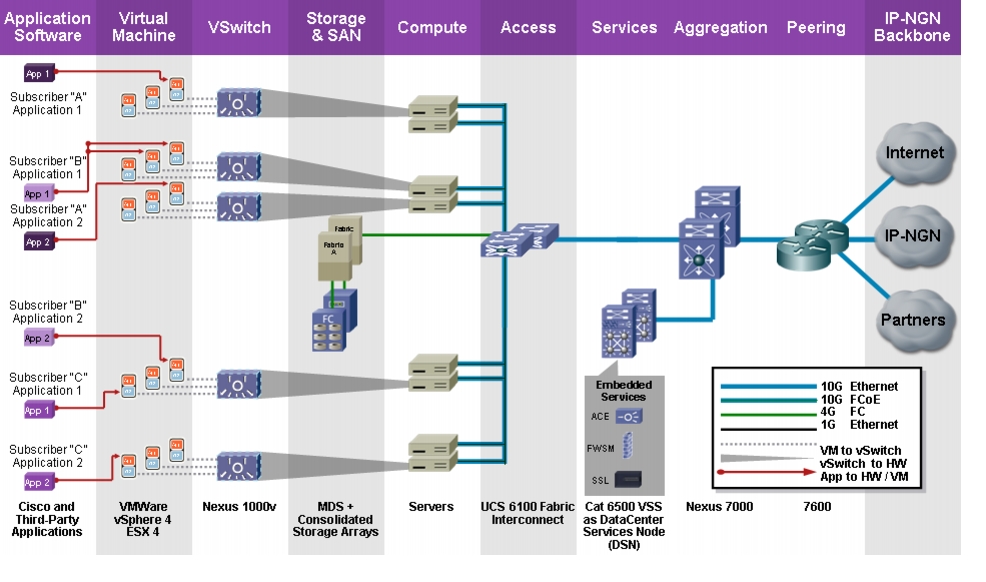
Figure 1-1 identifies the layers and platforms of the solution architecture.
Figure 1-1 Solution Architecture
The solution architecture consists of the following layers:
•
Virtual Compute. The virtual compute farm contains two UCS 5108 chassis with 16 UCS B200 servers (dual quad-core Intel Xeon X5570 CPU at 2.93 GHz, and 72 GB RAM) with 10 GE Menlo-Emulex converged network adapters (CNAs) organized into a VMware ESX cluster; and 32 servers (2 clusters) within a Compute Point-of-Delivery (PoD). Each server has two CNAs and are dual-attached to the UCS 6100 Fabric Interconnect. The CNAs provide LAN and SAN connectivity to the servers, which run VMware ESX4.0 hypervisor. The CNAs provide LAN and SAN services to the hypervisor.
•
Storage Array Network (SAN). This consists of storage arrays that support Fibre Channel (FC) and information lifecycle management (ILM) services. The storage arrays connect through MDS SAN switches to the UCS 6120 switches in the access layer.
•
VM Virtual Access Layer. Cisco Nexus 1000V DVS acts as the virtual access layer for the virtual machines (VMs). Edge LAN policies such as QoS marking and vNIC ACLs are implemented at this layer in Nexus 1000V port-profiles. There is one Nexus 1000V virtual supervisor module (VSM) per ESX cluster. Each ESX server runs an instance of the Nexus 1000V Virtual Ethernet Module (VEM).
•
Access Layer. In the Layer 2 access layer, redundant pairs of Cisco UCS 6120 switches aggregate VLANs from the Nexus 1000V DVS. FCoE SAN traffic from VMs are handed off as FC traffic to a pair of MDS SAN switches, and then to a pair of storage array controllers. FC expansion modules in the UCS 6120 switch provides SAN interconnects to dual SAN fabrics. The UCS 6120 switches are in N Port virtualization (NPV) mode to inter operate with the SAN fabric.
•
Aggregation. Redundant Cisco Nexus 7010 switches provide Layer 2 switching between compute nodes and PODs. The core supports Layer 2 multi-pathing to the access and services layers through virtual port-channels (vPCs). The Nexus 7010 switches serve as collapsed Core/Aggregation Layer 2 devices in this design.
•
Services Layer. A Data Center Service Node (DSN) virtual switching system (VSS)-a pair of Cisco Catalyst 6500 chassis with the VSS supervisors-provides L3 GW services and security services for the hosts. The Cisco Application Control Engine (ACE-20) and Cisco Firewall Services Module (FWSM) on the Catalyst 6500-VSS provide virtual firewall and server load-balancing services to the VMs. Dual FWSM and ACE modules are configured in an active/active high availability design.
Note
We use DSN and Virtual Switching System (VSS) interchangeably. A DSN refers to a Catalyst 6500 with installed FWSM and ACE services modules.
•
DC/WAN Edge or Peering. Redundant Cisco 7600 Series routers act as DC/WAN edge routers and provide 10GE connectivity for Internet, L3VPN, and L2VPN services. The 7600 Series router runs IS-IS and mpBGP routing protocols to the WAN/MPLS core and runs OSPF and BGP towards the cloud.
Note
We use DC Edge Router, Peering Router, and WAN Router interchangeably to refer to the Cisco 7600 router in this solution architecture.
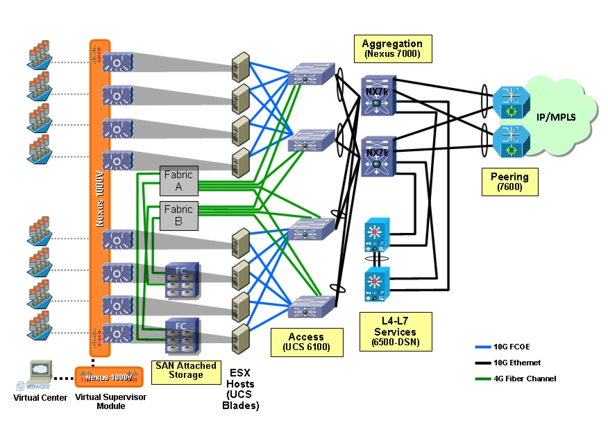
Figure 1-2 provides a detailed topology of the system architecture:
Figure 1-2 Solution Topology
Service Tiers
To tailor workload or application requirements to specific needs, you can offer service differentiation with a multi-tiered service infrastructure and Quality of Service (QoS) capabilities under a variable pricing model. Infrastructure and resource pools can be designed so customers can add or expand services easily by requesting additional compute, storage, or network capacity.
Virtualization technologies enable the following:
•
Virtual server resources with isolation and resource guarantees between multiple tenants on the same server.
•
Virtual pools of server resources to provide carrier-grade services, such as high availability and disaster recovery, automatic workload scaling and mobility.
•
Virtual storage to enable stateful workload management including snapshots, fast cloning, and dynamic provisioning.
•
Virtual network resources to provide multi-tenancy across pools of servers, with network isolation and resource guarantees, and the ability to manipulate and insert different virtualized Layer 3 to 7 networking functions for security, load balancing, application firewalling, protocol optimization, routing and other services.
•
Metering/billing of services on a usage basis, special reservation of services can be billed higher.
By varying some of the following capabilities, you can differentiate IaaS cloud services into pre-defined service profiles:
•
Virtual Machine Capabilities. There can be different service profiles based on VM sizing attributes like CPU, memory, storage capacity. Different service profiles can also have different VMware Distributed Resource Scheduling (DRS) profiles associated with them that can provide priority for different classes of VMs. For example, a Gold service can consist of VMs with dual core vCPU 3Ghz, with 8GB memory and 500GB storage. A Bronze service can consist of VMs with single core vCPU 1.5 GHz, with 2GB memory and 100GB storage.
•
Storage Capabilities. Service profiles can be differentiated based on the types of storage capabilities provided, such as RAID levels, disk types and speeds, backups and snapshot capabilities. For example, a Gold service can consist of 3 tiers of RAID-10 storage - 15k FC, 10k FC and SATA. While a Bronze service can consist of 1 tier of RAID-5 storage using SATA drives.
•
Application Tiering. Service bundles can offer differentiated support for application hosting. Different service profiles can have different layers or tiers of VMs. For example, a Gold profile can have three tiers (and three VLANs) to host Web, application, and database layers on different VMs. Each tier may have five VMs each for redundancy and load balancing. A Silver profile can also have three tiers for Web, App and DB layers, but each layer may only have two VMs each for redundancy and load balancing. A Bronze profile can have one tier only, with the Web, App and DB layers residing on the same VM.
•
Stateful Services. Customer or employee workloads can also be differentiated based on the additional services being applied to each tier. These services can be firewalls, encryption, load balancers, protocol optimization, application firewalls, WAN optimization, advanced routing, redundancy, disaster recovery, and so on. Even within a service like firewalls, there could be different tiers like inter-VLAN firewalling, intra-VLAN or intra-Host Firewalling, and so on. For example, a Gold profile might have Firewalls, SSL offload, IPSec encryption, server load balancers, and WAN Optimization included. While a Bronze profile may only offer Firewalls and server load balancers.
•
Quality of Service (QoS). The application of QoS is key to providing differentiated access to compute and storage resources in the cloud. Each service tier can have its own class of service defined for use through out the system with the desired QoS features applied to it. Each service class' aggregate traffic flow can be given differing levels of treatment through the cloud infrastructure wherever possible. Queuing and scheduling mechanisms can be utilized to offer minimum bandwidth guarantees to aggregate class traffic under periods of congestion. In addition to classifying traffic and providing priority during periods of high congestion, the provider can also limit access to the core of the cloud network. Besides network bandwidth, different service tiers can also have different resource guarantees - like Firewall or load balancer context resources, VMware DRS resource prioritization for compute, etc. For example, a Gold service tier may be given the highest priority and QoS, and a minimum guarantee of 50% of the network bandwidth; while a Bronze service tier may only get best-effort treatment, and no minimum bandwidth guarantees.
This solution defines three service tiers:
•
Bronze. Bronze service VMs have single core and up to 8 GB memory and 500 GB storage. The storage is single tier with SATA drives. The Bronze service class is marked with a CoS (Class of Service) value of 0 within the cloud and given 1% of the network/platform/link bandwidth. The Bronze service class includes one or two virtual machines and best effort compute and network resources allocation within the cloud network. The Bronze class is not provisioned for firewall or load balancer services, so it bypasses the ACE and FWSM service modules. All traffic from VMs is routed either to an L3 SVI on the DSN or directly to the 7600 DC/WAN Edge router.
•
Silver. Silver service VMs have single core and up to 8 GB memory and 1TB storage. The storage is two-tiered with 10k FC and SATA drives. The Silver service class is marked with a CoS (Class of Service) value of 1 within the cloud and given 10% of the network/platform/link bandwidth. The Silver service class includes ACE server load balancing, multiple virtual machines, and moderate compute and network resources allocations within the cloud network. These customers are configured for server load-balancing and are not provided firewall services. The virtual machines for Web, application, and DB layers are on a shared VLAN. All traffic from VMs is routed to the ACE, then to the L3 SVI on the DSN and then to the 7600 DC/WAN Edge router.
•
Gold. Gold service VMs have dual cores and up to 16 GB memory, and 2 TB storage. The storage is three-tiered with 15k FC, 10k FC, and SATA drives. The Gold service class includes ACE server load balancing, FWSM virtual firewall, multiple virtual machines, and the best compute and network resources allocations within the cloud network. The Gold service class is marked with a CoS (Class of Service) value of 2 within the cloud and given 88% of the network/platform/link bandwidth. The virtual machines for Web, applicaation, and DB layers are segregated into three separate VLANs. Each layer uses the FWSM virtual firewall as its gateway to route between VLANs or to the WAN/Internet (through the DSN and then 7600 DC/WAN Edge router).
Solution Components
This section presents information about Cisco hardware and software components and third party software components of the solution. It also discusses management components of the solution.
Cisco Hardware Components
This design is a combination of Cisco hardware components and software inter-operating with non-Cisco hardware components and software. Table 1-1 lists Cisco hardware products and components used in this design.
Table 1-1 Cisco Hardware Components
Product
|
Function
|
Component
|
Description
|
Cisco UCS
|
Unified Computing System
|
Cisco UCS 5108
|
8-slot UCS Blade Server Chassis
|
Cisco UCS 2104XP
|
4-port Fabric Extender
|
Cisco UCS 6120XP
|
20-port Fabric Interconnect
|
Cisco UCS B200 M1
|
Half-width Blade Server
|
Cisco UCS M71KR-E
|
Emulex Converged Network Adapter
|
Cisco Nexus 7000
|
Core/Aggregation
|
N7K-SUP1
|
Supervisor Module-1X
|
N7K-C7010-FAB
|
32-port 10Gbps Ethernet module
|
N7K-M132XP-12
|
32-port 10Gbps Ethernet module
|
Cisco Catalyst 6500 E
|
Data Center Services Node
Virtual Switching System
|
VS-S720-10G
|
Supervisor Engine 720 10GE
|
ACE20-MOD-K9
|
Application Control Engine Module
|
WS-SVC-FWM-1
|
Firewall Services Module
|
WS-X6708-10GE
|
8-port 10GE line card with DFC
|
WS-X6748-GE-TX
|
48-port 10/100/1000Mbps Ethernet line card
|
Cisco 6500 Switch
|
MPLS P/PE Router
|
WS-SUP720-3BXL
|
Supervisor Engine 720 10GE
|
WS-X6708-10GE
|
8-port 10GE line card with DFC
|
WS-X6704-10GE
|
4-port 10GE line card with DFC
|
WS-X6748-GE-TX
|
48-port 10/100/1000Mbps Ethernet line card
|
Cisco 7606
|
DC Edge/WAN Router
|
RSP720-3CXL-GE
|
Route Switch Processor 720
|
7600-ES+4TG3CXL
|
4-port 10 GE ES+ line card
|
WS-X6704-10GE
|
4-port 10GE line card with DFC
|
WS-X6708-10GE
|
8-port 10GE line card with DFC
|
Cisco MDS 9513
|
SAN Switch
|
DS-X9530-SF2-K9
|
Supervisor/Fabric-2
|
DS-X9124
|
½/4 Gbps FC Module
|
Cisco Software Components
All software images running on the Cisco hardware in this design are available from http://www.cisco.com and are listed in Table 1-2.
Table 1-2 Cisco Software Components
Product
|
Function
|
Component
|
Description
|
Software Version
|
Cisco Nexus 1000V
|
Virtual Access Switch
|
VSM
|
Virtual Supervisor Module
|
Cisco NX-OS 4.0(4)SV1(2)
|
VEM
|
VEM of VMware ESX hosts
|
4.0.4.1.2.0.80-0.4.179
|
Cisco UCS
|
Unified Computing System
|
UCSM
|
Unified Computing System Manager
|
1.0(2d)
|
UVS M71KR-E
|
Emulex Converged Network Adapter
|
1.0(2e)
|
Cisco Nexus 7000
|
Core/Aggregation Switch
|
N7K-SUP1
|
Supervisor module-1X
|
Cisco NX-OS 4.2(2a)
|
Cisco Catalyst 6509 E
|
Data Center Services Node
Virtual Switching System
|
VS-S720-10G
|
Supervisor Engine 720 10GE
|
IOS 12.2(33)SXI3
|
ACE20-MOD-K9
|
Application Control Engine
|
A2(1.6a)
|
WS-SVC-FVM-1
|
Firewall Services Module
|
4.0(7)
|
Cisco 6500 Switch
|
MPLS P/PE router
|
WS-SUP720-3BXL
|
Supervisor Engine 720 10GE
|
IOS 12.2(33)SXI3
|
Cisco 7606
|
DC Edge/WAN router
|
RSP720-3CXL-GE
|
Route Switch Processor 720
|
IOS 12.2(33)SRD3
|
Cisco MDS 9513
|
SAN Switch
|
DS-X9530-SF2-K9
|
Supervisor/Fabric-2
|
Cisco NX-OS 4.2(3)
|
Third-Party Software Components
The non-Cisco software used in this design is shown in Table 1-3.
Table 1-3 Third-Party Software Components
Vendor
|
Component
|
Software Versions
|
VMware
|
WMware vSphere Server
|
Enterprise Plus 4.0.0 Build 162856
|
VMware ESX
|
4.0.0 Building 164009 COS
|
VMware vSphere PowerCLI
|
4.0 U1 Build 208462
|
Microsoft
|
Windows Server 2003 R2
|
Standard x64 Edition Service Pack 1
|
SQL Server 2005
|
9.0
|
SQL Server Management Studio
|
9.00.1399.00
|
Windows PowerShell
|
1.0
|
Sun Microsystems
|
Java Runtime Environment
|
1.60_12 or above
|
Management Components
The non-Cisco software used in this design is shown in Table 1-4.
Table 1-4 Management Components
Component
|
Version
|
Cisco Fabric Manager
|
4.2(3)
|
Cisco Network Registrar
|
Release 7.0.1 Linux build #7.0.1.0809032302
|
Cisco LAN Management Solution
|
Version 3.0
|