Table Of Contents
About Cisco Validated Design (CVD) Program
Microsoft SharePoint 2010 on FlexPod for VMware
Audience/Who Should Read this Document
Solution Architecture Overview
Design Goals for SharePoint 2010 on FlexPod for VMware
Cisco Unified Network and FlexPod Add on Components
Cisco Wide Area Application Services for Branch Users
Data Center Design Best Practices
SharePoint on FlexPod on VMware
Microsoft SharePoint Server 2010 Enterprise Considerations
SharePoint Server 2010 Enterprise Capabilities
SharePoint 2010 Enterprise Services
SharePoint 2010 Evaluation Deployment
SharePoint 2010 Enterprise Deployment
VMware vSphere Virtualization Best Practices for SharePoint 2010
VMware vSphere 4.1 Deployment Considerations
Virtual Networking Best Practices
Guest Operating System Networking
M81KR (Palo) Network Interface
Nexus 1000V and Virtual Machine Networking
NAM Reporting from Nexus 1000V
Fibre-Channel Storage Area Network
UCS Service Profile Templates and Storage
Virtualizing MSCS Clustering for Microsoft SQL 2008 R2
Initial Configuration of VM Cluster Pair
MSCS HA and DRS Considerations
Cisco ACE and SharePoint 2010 Architecture
Branch and WAN and SharePoint 2010
WAAS Setup between Branch and Data Center
WAAS Setup for Remote User to Data Center
Data Center SharePoint on FlexPod
Validating SharePoint Server Performance
Cisco ACE and SharePoint 2010 Validation
Branch and WAN and SharePoint 2010 Validation
WAAS Mobile Performance Results
Appendix—ACE SharePoint 2010 Context Configuration
Microsoft SharePoint 2010 on FlexPod for VMwareLast Updated: April 18, 2011
Building Architectures to Solve Business Problems
About the Authors
David Antkowiak, Solutions Architect, Systems Architecture and Strategy Unit, Cisco SystemsDavid Antkowiak is a Solutions Architect with the Systems Architecture and Strategy Unit (SASU). With over 10 years of experience in various private and government organizations, his areas of focus have included virtual desktop infrastructure, server virtualization, cloud migration, and storage design. Prior to joining Cisco, David was Solutions Architect at JetBlue. David holds a masters degree from Florida State University and two VMware certifications.
Haseeb Niazi, Solutions Architect, Systems Architecture and Strategy Unit, Cisco SystemsHaseeb Niazi is a Solutions Architect in Cisco Systems Architecture and Strategy Unit (SASU) based in RTP North Carolina. Haseeb has over eleven years of experience dealing in optimization, security, and data center related technologies. As a member of various Solution Teams and Advanced Services, he has helped a large number of enterprise and service provider customers evaluate and deploy a wide range of Cisco solutions.
Haseeb holds a masters degree in computer engineering from University of Southern California and regularly presents to both internal and external audiences at various conferences and customer events. As part of SASU, Haseeb is currently leading the Application Velocity Validation effort.
AcknowledgementsThe authors would like to thank the following for their contribution to the design, validation, and creation of this validated design guide:
· Reena Gupta—NetApp, Reference Architect
· Rob Barker—NetApp, Reference Architect
· Nick DeRose—NetApp, Cisco Technical Alliance Manager
· Ramesh Isaac—Cisco, Technical Marketing Engineer
· Abhinav Joshi—Cisco, Solutions Architect
· Allan Wilson—Cisco, Solutions Architect
· Sean Gilbert—VMware, Sr. Alliance Technology Manager
· Aeisha Duncan—Cisco, Technical Marketing Engineer
· Chris O'Brien—Cisco, Solutions Architect
About Cisco Validated Design (CVD) Program
The CVD program consists of systems and solutions designed, tested, and documented to facilitate faster, more reliable, and more predictable customer deployments. For more information visit http://www.cisco.com/go/designzone.
ALL DESIGNS, SPECIFICATIONS, STATEMENTS, INFORMATION, AND RECOMMENDATIONS (COLLECTIVELY, "DESIGNS") IN THIS MANUAL ARE PRESENTED "AS IS," WITH ALL FAULTS. CISCO AND ITS SUPPLIERS DISCLAIM ALL WARRANTIES, INCLUDING, WITHOUT LIMITATION, THE WARRANTY OF MERCHANTABILITY, FITNESS FOR A PARTICULAR PURPOSE AND NONINFRINGEMENT OR ARISING FROM A COURSE OF DEALING, USAGE, OR TRADE PRACTICE. IN NO EVENT SHALL CISCO OR ITS SUPPLIERS BE LIABLE FOR ANY INDIRECT, SPECIAL, CONSEQUENTIAL, OR INCIDENTAL DAMAGES, INCLUDING, WITHOUT LIMITATION, LOST PROFITS OR LOSS OR DAMAGE TO DATA ARISING OUT OF THE USE OR INABILITY TO USE THE DESIGNS, EVEN IF CISCO OR ITS SUPPLIERS HAVE BEEN ADVISED OF THE POSSIBILITY OF SUCH DAMAGES.
THE DESIGNS ARE SUBJECT TO CHANGE WITHOUT NOTICE. USERS ARE SOLELY RESPONSIBLE FOR THEIR APPLICATION OF THE DESIGNS. THE DESIGNS DO NOT CONSTITUTE THE TECHNICAL OR OTHER PROFESSIONAL ADVICE OF CISCO, ITS SUPPLIERS OR PARTNERS. USERS SHOULD CONSULT THEIR OWN TECHNICAL ADVISORS BEFORE IMPLEMENTING THE DESIGNS. RESULTS MAY VARY DEPENDING ON FACTORS NOT TESTED BY CISCO.
The Cisco implementation of TCP header compression is an adaptation of a program developed by the University of California, Berkeley (UCB) as part of UCB's public domain version of the UNIX operating system. All rights reserved. Copyright © 1981, Regents of the University of California.
Cisco and the Cisco Logo are trademarks of Cisco Systems, Inc. and/or its affiliates in the U.S. and other countries. A listing of Cisco's trademarks can be found at http://www.cisco.com/go/trademarks. Third party trademarks mentioned are the property of their respective owners. The use of the word partner does not imply a partnership relationship between Cisco and any other company. (1005R)
Any Internet Protocol (IP) addresses and phone numbers used in this document are not intended to be actual addresses and phone numbers. Any examples, command display output, network topology diagrams, and other figures included in the document are shown for illustrative purposes only. Any use of actual IP addresses or phone numbers in illustrative content is unintentional and coincidental.
Microsoft SharePoint 2010 on FlexPod for VMware
© 2011 Cisco Systems, Inc. All rights reserved.
Microsoft SharePoint 2010 on FlexPod for VMware
Introduction
Purpose
This SharePoint 2010 Enterprise deployment on FlexPod™ for VMware® design guide demonstrates how enterprises can apply best practices for VMware vSphere™, VMware vCenter™, Cisco® Unified Computing System™ (UCS), Cisco Nexus® family switches, and NetApp® FAS®. Design validation was completed using Microsoft® Visual Studio 2010 Ultimate workloads and Visual Studio Load Test agents simulating a realistic 50000 user load across SharePoint 2010 Enterprise features. Virtual user connections from branch offices, remote offices, and mobile users were optimized using Cisco Wide Area Application Services (WAAS). Cisco Application Control Engine (ACE) was implemented for Web and application server load balancing within the SharePoint 2010 architecture.
Audience/Who Should Read this Document
This guide is intended for the reader with any or all of the following:
•
Deals with high level design guidance for SharePoint 2010
•
•
•
•
•
•
•
•
Reference Material
•
http://technet.microsoft.com/en-us/sharepoint/ee263917•
http://www.netapp.com/us/technology/flexpod/•
http://www.cisco.com/en/US/products/ps5680/Products_Sub_Category_Home.html•
http://www.cisco.com/en/US/products/ps6906/index.htmlBusiness Requirements
Tier 1 business applications are moving into the consolidated compute, network, and storage environment. Through FlexPod for VMware every component of a traditional SharePoint 2010 Enterprise deployment is reduced. Management integration and complexity is simplified while maintaining SharePoint 2010 design and implementation options. Administration is unified, while process separation can be adequately controlled and monitored. We have aimed to achieve the following business requirements for SharePoint 2010:
•
•
•
•
•
Solution Architecture Overview
Design Goals for SharePoint 2010 on FlexPod for VMware
This Microsoft SharePoint 2010 Enterprise on FlexPod for VMware guide provides a functional review and analysis for application deployment within the Cisco Unified network architecture. The test areas include scalability, optimization, availability, and load balancing of a VMware virtualized SharePoint 2010 environment with a 50,000 user maximum workload scenario simulating enterprise use cases across Microsoft SharePoint 2010 features.
•
•
•
Show single vSphere 4.1 host failure availability of workload across the SharePoint 2010 farm servers. A vSphere 4.1 hardware failure is initiated and a new blade brought online using the existing service profile and boot configuration of the failed UCS blade.
Show nexus 1010 hardware availability of workload across the SharePoint 2010 Web farm servers.
Show VMware HA VM restart of workload across the SharePoint 2010 farm servers. A vSphere 4.1 hardware failure is initiated and restart behavior shows HA functionality restarting VMs on remaining ESX hosts.
Provide Microsoft Server Clustering guidance and availability results
•
High Level Architecture
Description
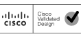
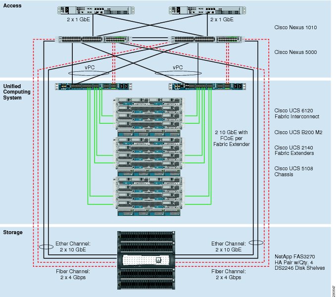
Figure 1 is an end-to-end view of the SharePoint 2010 Enterprise on FlexPod for VMware design. It includes all physical architecture components and branch user access entry points. Both the data center and branch topologies are discussed in detail throughout the document.
Figure 1 High Level Architecture Diagram
Data Center High Level Design
Description
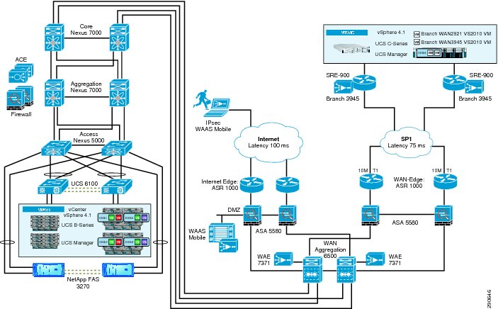
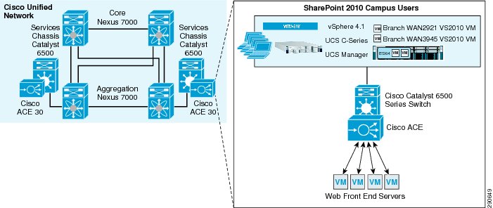
The topology in Figure 2 illustrates all physical data center architecture components. FlexPod for VMware, Cisco Unified Network sections, and the Campus User Environment are outlined.
Figure 2 Data Center High Level Design Diagram
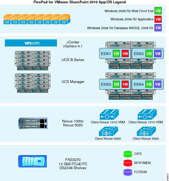
FlexPod for VMware
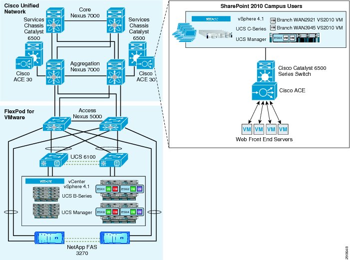
FlexPod is a defined set of hardware and software that serves as an integrated infrastructure stack for all virtualization solutions. FlexPod for VMware includes NetApp storage, Cisco networking, the Cisco Unified Computing System, and VMware virtualization software in a single package. This solution was deployed and tested on this defined set of hardware and software. For detailed information about the core FlexPod on VMware architecture, see: http://www.netapp.com/us/technology/flexpod/.
Figure 3 High Level FlexPod for VMware
VMware vSphere 4.1
VMware vSphere provides infrastructure services and application services for higher consolidation ratios while delivering service level controls for storage and network resources.
The VMware ESXi™ hypervisor abstracts server hardware resources enabling highly efficient CPU scheduling for application performance while maintaining high consolidation ratios. Additionally, ESXi consolidation memory features include compression, page sharing, ballooning, and swapping. vSphere 4.1 ESXi combined with UCS's extended memory footprint increases performance and capacity for SharePoint 2010 deployments.
vSphere 4.1 relies on VMware vCenter server for infrastructure and application services management. This unified management foundation has several partner integration points that provide additional functionality and management consolidation. vCenter combines standardized VM provisioning with templates, host compliance with host profiles, and patch automation with VMware update manager. Additional areas of management include distributed resource optimization and high availability.
VMware vCenter offers administrators automation, visibility, and operational unification in the form of network, storage, and compute resource plug-ins.
•
•
•
Cisco Unified Computing System
The Cisco Unified Computing System combines compute, network, storage access, and virtualization providing a 10 Gigabit Ethernet unified network fabric with an enterprise-class server architecture. The Cisco Unified Computing System is designed to deliver:
•
•
•
•
•
Table 1 lists the processor and memory configurations for the UCS servers in this design guide.
I/O Adapters
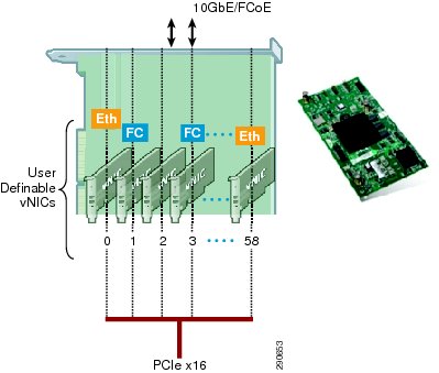
The Cisco UCS blade server has various Converged Network Adapters (CNA) options. The UCS M81KR Virtual Interface Card (VIC) option was used in this Cisco Validated Design:
UCS M81KR VIC (a.k.a Palo) provides the capability to create multiple vNICs (up to 128 in version 1.4) on the CNA. This allows complete I/O configurations to be provisioned in virtualized or non-virtualized environments using just-in-time provisioning, providing tremendous system flexibility and allowing consolidation of multiple physical adapters.
System security and manageability is improved by providing visibility and portability of network policies and security all the way to the virtual machines. Additional M81KR features like VN-Link technology and pass-through switching minimize implementation overhead and complexity.
Figure 4 Cisco UCS M81KR VIC
Cisco UCS 2100 Series Fabric Extenders
Cisco UCS 2100 Series Fabric Extenders bring the unified fabric into the blade server enclosure, providing 10 Gigabit Ethernet connections between blade servers and the fabric interconnect, simplifying diagnostics, cabling, and management.
The Cisco UCS 2100 Series extends the I/O fabric between the Cisco UCS 6100 Series Fabric Interconnects and the Cisco UCS 5100 Series Blade Server Chassis, enabling a lossless and deterministic Fibre Channel over Ethernet (FCoE) fabric to connect all blades and chassis together. Since the fabric extender is similar to a distributed line card, it does not do any switching and is managed as an extension of the fabric interconnects.
The following list describes some functions and features of the UCS 2100 Fabric Extenders:
•
•
•
•
•
•
This approach removes switching from the chassis, reducing overall infrastructure complexity and enabling the Cisco Unified Computing System to scale to many chassis without multiplying the number of switches needed, reducing TCO and allowing all chassis to be managed as a single, highly-available management domain.
UCS 6100 XP Series Fabric Interconnect
The Cisco UCS 6100 Series Fabric Interconnects are a core part of the Cisco UCS, providing both network connectivity and management capabilities for the system. The Cisco UCS 6100 Series offers line-rate, low-latency, lossless 10 Gigabit Ethernet and Fibre Channel over Ethernet (FCoE) functions.
The Cisco UCS 6100 Series provides an integrated and unified management and communication backbone for the Cisco UCS B-Series Blade Servers and UCS 5100 Series Blade Server Chassis. Management systems in older classical server designs employ a series of interfaced software management modules that are interconnected to give the appearance of a unified system until the need to troubleshoot them reveals their inherent complexity and increased operational costs for your IT team. All chassis, and therefore all blades, attached to the Cisco UCS 6100 Series Fabric Interconnects become part of a single, highly-available unified management domain. In addition, by supporting unified fabric, the Cisco UCS 6100 Series provides both the LAN and SAN connectivity for all blades within its domain. The Cisco UCS 6120XP is a 1 RU fabric interconnect and provides:
•
•
•
•
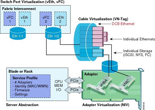
Cisco UCS Infrastructure Virtualization Abstraction
Figure 5 Infrastructure Virtualization Abstractions
UCS Manager and Service Profiles
Cisco UCS Manager
Cisco UCS Manager integrates compute, network, storage access, and virtualization into a single, unified, and cohesive system. Cisco UCS Manager provides unified management domain with centralized management capabilities. Cisco UCS Manager is embedded device management software that manages the system end-to-end as a single logical entity through an intuitive GUI, a command line interface (CLI), or an XML API (http://developer.cisco.com/web/unifiedcomputing/start).
Service Profiles
Cisco UCS Manager provisions servers utilizing service profiles. Service profile templates are stored in the Cisco UCS 6100 Series Fabric Interconnects for reuse by server, network, and storage administrators. Service profile templates consist of server requirements and the associated LAN and SAN connectivity. When a service profile is deployed to a server, Cisco UCS Manager automatically configures the server, adapters, fabric extenders, and fabric interconnects to match the configuration specified in the service profile.
This automation of device configuration reduces the number of manual steps required to configure servers, network interface cards (NICs), host bus adapters (HBAs), and LAN and SAN switches.
Nexus 1010
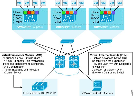
The Cisco Nexus 1010 Virtual Services Appliance is a member of the Cisco Nexus 1000V Series Switches. It hosts the Cisco Nexus 1000V Virtual Supervisor Module (VSM) and supports the Cisco Nexus 1000V Network Analysis Module (NAM) Virtual Service Blade to provide a comprehensive solution for virtual access switching. Because the Cisco Nexus 1010 provides dedicated hardware for the VSM, it makes virtual access switch deployment much easier for the network administrator. With its support for additional virtual service blades, such as the Cisco Nexus 1000V NAM Virtual Service Blade, the Cisco Nexus 1010 is a crucial component of a virtual access switch solution.
Nexus 1000V Virtual Switch
Cisco Nexus 1000V Series Switches are virtual machine access switches that are an intelligent software switch implementation for VMware vSphere environments. Operating inside the VMware ESX hypervisor, the industry-unique Cisco Nexus 1000V Series supports Cisco VN-Link server virtualization technology to provide policy-based VM connectivity, mobile VM security, network policy, and non-disruptive operational model for your server virtualization and networking teams. Developed in close collaboration with VMware, the Cisco Nexus 1000V Series is certified by VMware to be compatible with VMware vSphere, vCenter, ESX, and ESXi.
Figure 6 Nexus 1000V
Nexus 5000
Cisco Nexus 5000 Series Switches provide a unified, converged fabric over 10 Gigabit Ethernet for LAN, SAN, and cluster traffic. This unification enables network consolidation and greater utilization of previously separate infrastructure and cabling, reducing by up to 50 percent the number of adapters and cables required and eliminating redundant switches. These multipurpose, multilayer switches are deployed as part of the FlexPod for VMware access layer and provide:
•
•
•
•
•
•
NetApp Storage Technologies and Benefits
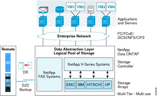
Data ONTAP 8
NetApp solutions begin with Data ONTAP 8 (http://www.netapp.com/us/products/platform-os/data-ontap-8/?REF_SOURCE=ntpggl8700000018115s), the fundamental software platform that runs on all NetApp storage systems. Data ONTAP is a highly optimized, scalable operating system that supports mixed NAS and SAN environments and a range of protocols, including Fibre Channel, iSCSI, FCoE, NFS, and CIFS. It also includes a patented file system and storage virtualization capabilities called WAFL (Write Anywhere File Layout). Leveraging the Data ONTAP platform, the NetApp Unified Storage Architecture offers the flexibility to manage, support, and scale to business environments by using a single set of knowledge and tools. From the remote office to the data center, customers collect, distribute, and manage data from all locations and applications at the same time. This allows the investment to scale by standardizing processes, cutting management time, and increasing availability.
Figure 7 NetApp Unified Architecture
Data Protection
Many people overlook Data Protection as a complex set of processes and products, costly, and in need of a drastic change with the emergence of virtualization. With NetApp, Microsoft administrators are provided with integrated data protection across their entire portfolio of products and services, thus eliminating the cost and complexity of data protection. Data protection is built across the entire family of NetApp FAS systems so there is no relearning of new technologies as you scale up or scale down. These technologies include RAID-DP®, SnapShot, SnapManager for VMware, SnapManager for SharePoint, SnapManager for SQL, NetApp SnapMirror®, and NetApp Snapshot copies are critical components of the NetApp solution that help address storage availability.
RAID-DP
With any Microsoft SharePoint deployment, data protection is critical because any RAID failure could result in hundreds to thousands of end users being disconnected, which results in lost productivity. RAID-DP provides performance that is comparable to that of RAID 10, yet requires fewer disks to achieve equivalent protection. RAID-DP provides protection against double disk failure as compared to RAID 5, which can only protect against one disk failure per RAID group. For more information about RAID DP, see NetApp TR-3298: RAID-DP: NetApp Implementation of RAID Double Parity for Data Protection (http://www.netapp.com/us/library/technical-reports/tr-3298.html).
Snapshot
NetApp Snapshot technology provides zero-cost, near-instantaneous point-in-time copies of the file system (volume) or LUN by preserving Data ONTAP WAFL consistency points.
There is no performance penalty for creating Snapshot copies, because data is never moved, as it is with other copy-out technologies. The cost for Snapshot copies is only at the rate of block-level changes, not 100% for each backup, as with mirror copies. This means savings in storage costs for backup and restore purposes and opens up a number of possibilities for efficient data management.
Thin Provisioning and FlexVol
Thin provisioning is a function of NetApp FlexVol®, which allows storage to be provisioned just like traditional storage. However, storage is not consumed until the data is written (just-in-time storage).Thin Provisioning relies on on-demand allocation of blocks of data, rather than the traditional method of allocating all the blocks up front. Thin provisioning eliminates almost all whitespace, which helps avoid poor utilization rates.
The enabling technology behind NetApp thin provisioning is WAFL, which can be thought of as the virtualization layer of Data ONTAP. When a LUN or volume is created, WAFL does not dedicate specific blocks out of the NetApp volume for the LUN or volume or for Snapshot copies of the LUN or volume. Instead, it allocates the blocks from the NetApp aggregate when the data is actually written. This allows the administrator to provision more storage space, as seen from the connected servers, than is actually physically present in the storage system.
NetApp Deduplication
Data deduplication is a data compression technique for eliminating coarse-grained redundant data, typically to improve storage utilization. NetApp deduplication is a fundamental component of Data ONTAP, NetApp's core operating architecture. NetApp deduplication combines the benefits of granularity, performance, and resiliency with a significant advantage in the race to improve storage utilization demands.
The deduplication process stores only unique blocks of data in the volume and creates additional metadata in the process.
Each 4k block in the storage system has a digital fingerprint, which is compared to other fingerprints in the volume. If two fingerprints are found to be the same, a byte-for-byte comparison is done of all bytes in the block. If they are an exact match, the duplicate block is discarded and the space is reclaimed.
The core enabling technology of deduplication is fingerprints. When deduplication runs for the first time on a flexible volume with existing data, it scans the blocks in the volume and creates a fingerprint database, which contains a sorted list of all fingerprints for used blocks in the volume.
Deduplication consumes system resources and can alter the data layout on disk. Due to the application I/O pattern and the effect of deduplication on the data layout, the read and write I/O performance can vary.
Figure 8 NetApp Deduplication
Note
Tests show that space savings on a CIFS share can be up to 35% to 40% and space savings in SharePoint content databases are approximately 30% on average.
Adequate space must be available on the flexible volume for the sis on command to complete successfully. If the sis on command is attempted on a flexible volume that already has data and is completely full, it fails because there is no space to create the required metadata.
FlexClone
A NetApp FlexClone volume is a writable point-in-time Snapshot copy of a FlexVol volume or another FlexClone volume. FlexClone uses space very efficiently, leveraging the Data ONTAP architecture to store only data that changes between the parent and the clone. FlexClone volumes are useful in any situation where testing or development occurs, any situation where progress is made by locking in incremental improvements, and any situation where it is necessary to distribute data in changeable form without endangering the integrity of the original.
NetApp Virtual Storage Console
NetApp virtual storage console for vCenter integrates a number of storage management components. These feature sets include the virtual storage console itself, provisioning and cloning, and backup and recovery. Within the virtual storage console, administrators are now given visibility into the array structure not previously available. Datastore mapping information can now be directly access from the virtual storage console plug-in tab. Layered storage capacity reporting enables administrators to view VMFS, LUN, FlexVol, and aggregate information.
For more information on VSC, see:
https://now.netapp.com/NOW/knowledge/docs/hba/vsc/relvsc201/html/index.shtmlCisco Unified Network and FlexPod Add on Components
Description
In addition to the FlexPod for VMware implementation, other key Cisco technologies are utilized in this design. The Nexus 7000 series switches are implemented for a high speed redundant core and aggregation layer providing maximum switching throughput. High availability and flexibility is achieved at the aggregation layer with an addition of a Services Chassis model. This model enables Cisco Application Control Engine (ACE) modules to fulfill application load balancing demands and provide integration with the virtualization implementation.
Figure 9 Cisco Unified Network and FlexPod Add On Components
Enterprise Core
A pair of Nexus 7000s act as an enterprise core handling the traffic from all the zones (WAN aggregation, campus, etc.) in the enterprise. The core network has been kept very simple by design as the sole purpose of a high-speed core is to switch packets efficiently. The Core Nexus 7000 is configured as a Layer 3 network.
Data Center Aggregation Layer
A pair of Nexus 7000s act as the data center aggregation layer. Cisco Nexus 5000 constitutes the data center access layer and connects to the Nexus 7000s in the aggregation layer. Each Nexus 5000 is connected to both the aggregation switches using two 10Gbps connections, for a total of 4 10Gbps connections. These links are configured with Virtual Port Channels (VPCs) to provide non-blocking 40Gbps total throughput.
For information about Nexus 7000 Series Switches, see:
http://www.cisco.com/en/US/products/ps9402/index.html.Services Chassis
This design includes the implementation of an additional pair of Cisco 6500 chassis adjacent to the aggregation layer of the data center network. These switches are commonly referred to as Services Chassis. The Services Chassis model uses a dual-homed approach for data path connectivity of the Services Chassis into both of the aggregation layer switches. This approach decouples the service modules from dependence on a specific aggregation switch. This provides operational flexibility for system maintenance that may be required to the aggregation switches or the services switches. From a high availability perspective, if one of the aggregation switches fails, traffic can continue to flow through the other aggregation switch to the active service modules without any failover event needing to occur with the service modules themselves.
For more information about the Service Chassis, see:
http://www.cisco.com/en/US/docs/solutions/Enterprise/Data_Center/dc_servchas/service-chassis_design.html#wp58903.2.4.5 SharePoint 2010 Enterprise and Cisco Application Control Engine
Cisco Application Control Engine Overview
The Cisco Application Control Engine (ACE) provides improved application availability, load balancing, scalability, and increased performance. ACE also features context virtualization, role-based access control, and VMware vCenter integration to facilitate application provisioning and visibility. These features combined with a multi-tier application design deliver the greatest potential for Cisco ACE integration.
Load Balancing for an SharePoint 2010 Environment
Cisco ACE delivers SharePoint 2010 deployments with multi-tier application high availability for end user experience improvement, automated application monitoring, and traffic reporting. Cisco ACE hardware load balancers can improve CPU utilization distribution in virtualized environments by taking advantage of targeted CPU sizing for WFEs. This involves fewer minimum requirements for each virtual machine's CPU and memory and allows for Cisco ACE to distribute the client loads more evenly, while the VMware distributed resource scheduler enables clustered ESXi systems to meet targeted CPU utilization.
Additionally, as the SharePoint 2010 environment expands to encompass additional services and features, dedicated WFE farms can be deployed and utilized quickly. Cisco ACE can also provide additional contexts for securing different WFE farms within the same topology.
Branch and WAN Design
Description
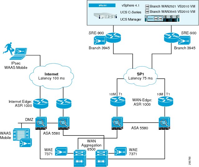
Figure 10 provides a simple, high-level view of the branch topology and the link latency for branch users.
Branch user access includes the Cisco Wide Area Application (WAAS) running on Service Ready Engine (SRE) implementation. The WAAS mobile users are also shown in Figure 10 with the WAAS Mobile implementation to optimize the higher remote link latency.
Figure 10 Branch and WAN Design Diagram
Cisco Wide Area Application Services for Branch Users
Cisco WAAS
To provide optimization and acceleration services between the branch and data center, a Cisco WAAS appliance was deployed at the data center WAN aggregation tier in a one-armed deployment and a WAAS running on Service Ready Engine (SRE) was deployed in the Integrated Services Generation 2 (ISR-G2) router at the branch. To appreciate how the Cisco Wide Area Application Services (Cisco WAAS) provides WAN optimization and application acceleration benefits to the enterprise, consider the basic types of centralized application messages that are transmitted between remote branches.
For simplicity, two basic types are identified:
•
•
–
–
Advanced Compression Using DRE and LZ Compression
Data Redundancy Elimination (DRE) is an advanced form of network compression that allows the Cisco WAAS to maintain an application-independent history of previously-seen data from TCP byte streams. Lempel-Ziv (LZ) compression uses a standard compression algorithm for lossless storage. The combination of using DRE and LZ reduces the number of redundant packets that traverse the WAN, thereby conserving WAN bandwidth, improving application transaction performance, and significantly reducing the time for repeated bulk transfers of the same application.
TCP Flow Optimization
The Cisco WAAS TCP Flow Optimization (TFO) uses a robust TCP proxy to safely optimize TCP at the Cisco WAE device by applying TCP-compliant optimizations to shield the clients and servers from poor TCP behavior due to WAN conditions. The Cisco WAAS TFO improves throughput and reliability for clients and servers in WAN environments through increases in the TCP window sizing and scaling enhancements—as well as through the implementation of congestion management and recovery techniques—to ensure that the maximum throughput is restored in the event of packet loss.
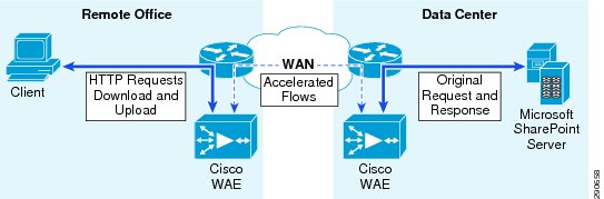
The Cisco WAAS uses the technologies described in the previous section to enable optimized SharePoint 2010 experience between the branch office users and Web front end servers by providing TFO optimization, LZ compression, and DRE caching.
Figure 11 WAAS SharePoint 2010 Accelerated Traffic
WAAS Mobile
In addition to Cisco WAAS for branch optimization, Cisco offers Cisco WAAS Mobile for telecommuters, mobile users, and small branch and home office users who access corporate networks and need accelerated application performance. Cisco WAAS Mobile client is purpose-built for Microsoft Windows® PCs and laptops. To provide WAAS Mobile services to remote users, a WAAS Mobile server was deployed as a virtual machine on the Unified Computing System to support user connections into the data center SharePoint 2010 server farm.
Advanced Data Transfer Compression
Cisco WAAS Mobile maintains a persistent and bi-directional history of data on both the mobile PC and the Cisco WAAS Mobile server. This history can be used in current and future transfers, across different VPN sessions, or after a reboot, to minimize bandwidth consumption and to improve performance. In addition, instead of using a single algorithm for all file types, Cisco WAAS Mobile uses a file-format specific compression to provide higher-density compression than generic compression for Microsoft Word, Excel, and PowerPoint files, Adobe Shockwave Flash (SWF) files, ZIP files, and JPEG, GIF, and PNG files.
Application-Specific Acceleration
Cisco WAAS Mobile reduces application-specific latency for a broad range of applications, including Windows file servers, or network-attached storage using CIFS, HTTP, HTTPS, and other TCP-based applications.
Transport Optimization
Cisco WAAS Mobile extends Cisco WAAS technologies to handle the timing variations found in packet switched wireless networks, the significant bandwidth latency problems of broadband satellite links, and noisy Wi-Fi and digital subscriber line (DSL) connections. The result is significantly higher link resiliency.
Data Center Design Best Practices
SharePoint on FlexPod on VMware
SharePoint 2010 on FlexPod for VMware provides the various options for usage and capacity requirements. The FlexPod for VMware solution was designed to host scalable, mixed application workloads. The scope of this CVD is limited to the SharePoint 2010 deployment only. The SharePoint farm consisted of the following virtual machines:
•
•
•
These VMs (including the other core infrastructure VMs) were deployed using the NetApp VSC vCenter plug-in for VMware vSphere 4.1.
Figure 12 SharePoint 2010 VM Deployment
SharePoint 2010 Servers
SharePoint 2010 operates on a three-tier model for role deployment. These role deployments will vary based on enterprise implementation requirements. SharePoint 2010 gives enterprise scaling flexibility while continuing to offer the same set of features for all business needs. This solution uses dedicated UCS servers for all three roles, i.e., Web front end, application, and database.
Web Front End Server Role
The Web front end (WFE) role is typically defined by servers running the Microsoft SharePoint Foundation Web Application service. Other additional services incorporated at this tier may include Search Query and Site Settings Service. Scaling out the Web front end roles is the best approach for larger enterprise deployments. In this solution Cisco ACE provided the desired load balancing of the WFE tier.
Application Server Role
The application server role encompasses the largest set of services. Servers in this tier typically host the services listed below. The application tier may also be dedicated to index and crawl functions for the SharePoint farm.
SharePoint 2010 Services
http://sharepoint.microsoft.com/en-us/product/Pages/Features.aspx•
•
•
•
•
•
•
•
•
•
•
•
•
•
•
•
•
•
•
•
•
•
•
•
Database Server Role
The database server role comprises a supported version of Microsoft SQL Server. Deployment criteria for enterprise solutions include increased scale-out and scale-up workload by clustering server nodes. Microsoft SQL sizing, version, and scalability are directly dependent on implementation of SharePoint 2010 features and services. Typical configurations for larger SharePoint 2010 database environments include highly available clusters.
For additional database guidance, refer to Microsoft capacity and co-location guidance models: Databases That Support SharePoint 2010 Products (http://www.microsoft.com/downloads/en/details.aspx?FamilyID=990041e5-0a73-4d2f-895d-2232d1a229f5&displaylang=en).
Microsoft SharePoint Server 2010 Enterprise Considerations
SharePoint 2010 sizing can typically be determined using feature support, size of organization, and availability needs. A discovery process should be conducted in various stages and provide administrators with testing opportunities during each stage, ensuring stability and scalability while meeting user demand for content, experienc,e and features.
SharePoint Server 2010 Enterprise Capabilities
Microsoft SharePoint Server 2010 Enterprise contains a number of features and services.
•
•
•
•
•
•
Understanding these application capabilities is crucial to successful deployment. CPU and memory consumption by SharePoint 2010 services applications can vary greatly at each server tier. Additional information can be found in Microsoft TechNet at: Capacity management and sizing overview for SharePoint Server 2010 (http://technet.microsoft.com/en-us/library/ff758647.aspx).
SharePoint 2010 Enterprise Services
This enterprise design contains SharePoint 2010 services determined by current trending of customer feature relevance. The areas selected were:
•
–
–
–
•
–
–
•
–
–
•
–
–
–
–
•
–
–
–
•
–
–
–
Server and Virtualization
SharePoint 2010 Evaluation Deployment
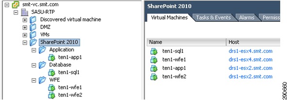
The evaluation deployment should be utilized to baseline workload, concurrent users, and expected requests per second. This should be minimally representative of the expected production implementation to provide sufficient feature evaluation. The environment was composed of two Web front end servers, one application server, and one database server. Initially the application server and database server provided functionality testing of basic SharePoint features. The CPU and memory configurations in Table 3 were created.
Figure 13 SharePoint 2010 Evaluation Virtual Machines
The evaluation environment was utilized during verification of Visual Studio 2010 testing tools, request per second thresholds, and concurrent user setting for baseline scaling of SharePoint 2010 services and features.
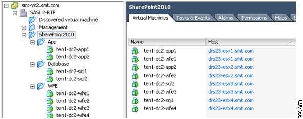
SharePoint 2010 Enterprise Deployment
The enterprise deployment design was determined using results from the evaluation deployment based on concurrent user, request per second, and page response times for different features. The final design incorporated additional UCS, VMware, and NetApp end-to-end solution components. These were in place during the validation phase of the environment. The environment was comprised of four Web front end servers, two application servers, and a clustered database server leveraging Windows Failover clustering.
The CPU and memory configurations in Table 4 were created.
Figure 14 SharePoint 2010 Enterprise Virtual Machines
VMware vSphere Virtualization Best Practices for SharePoint 2010
SharePoint 2010 provides an opportunity to take advantage of some specific performance enhancements of VMware vSphere. In conjunction with Microsoft recommendations for SharePoint 2010 virtualization and VMware testing, we can provide some basic guidelines for the application, Web, and database roles. SharePoint 2010 gives administrators a large amount of flexibility with roles and services. The typical deployment for SharePoint will go through a number of evolutionary stages with server roles being redistributed based on feature sets and scalability. VMware vSphere provides the ability to rapidly change CPU and memory configurations during evaluations, proof of concept, and user acceptance implementations.
Ensure you check all VM guest OS application requirements and software constraints.
For more information, see:
•
•
VMware vSphere 4.1 Deployment Considerations
Cisco ISO install
All UCS systems running ESXi should be installed using the VMware ESXi 4.1 installable Cisco Customized ISO Image available at: http://downloads.vmware.com/d/details/esxi41_cisco_oem_iso/ZHcqYnRkdHdiZCpldw==.
CPU Configuration Guidelines
Physical and Virtual CPUs
VMware uses the terms virtual CPU (vCPU) and physical CPU to distinguish between the processors within the virtual machine and the underlying physical x86/x64-based processor cores. Virtual machines with more than one virtual CPU are also called SMP (symmetric multi-processing) virtual machines. The virtual machine monitor (VMM) is responsible for virtualizing the CPUs. When a virtual machine starts running, control transfers to the VMM, which is responsible for virtualizing guest OS instructions.
Virtual SMP
VMware Virtual Symmetric Multi-Processing™ (Virtual SMP) enhances virtual machine performance by enabling a single virtual machine to use multiple physical processor cores simultaneously. vSphere supports use of up to eight virtual CPUs per virtual machine. SharePoint 2010 can take advantage of virtual SMP and all systems in this deployment utilize multiple vCPUs. This flexibility with VMware allows quick scaling to address potential processing bottle necks on WFEs, application servers, or database virtual machines.
Ensure you follow best practices with using SMP in your SharePoint 2010 deployment.
•
•
•
CPU Scheduling
In VMware ESX™ 4.1, the CPU scheduler has undergone several improvements to provide better performance and scalability; for details, see the paper VMware vSphere 4.1: The CPU Scheduler in VMware ESX 4.1 (http://www.vmware.com/files/pdf/techpaper/VMW_vSphere41_cpu_schedule_ESX.pdf). For example, in ESX 4.1, the relaxed co-scheduling algorithm has been refined so that scheduling constraints due to co-scheduling requirements are further reduced.
While larger virtual machines are possible in vSphere, VMware recommends reducing the number of virtual CPUs if monitoring of the actual workload shows that the application is not benefitting from the increased virtual CPUs. For more background, see the "ESX CPU Considerations" section in the white paper Performance Best Practices for VMware vSphere 4.1 (http://www.vmware.com/pdf/Perf_Best_Practices_vSphere4.1.pdf).
Consider Virtual machine vCPU scaling when selecting UCS blade types and processor cores to help determine a deployment target. Use the evaluation process in determining consolidation ratio and CPU utilization goals. Consider scaling out some tiers and scaling up others to achieve the target goals of consolidation, utilization, and availability. Beware of ready times and adjust your vCPUs accordingly.
NUMA-Aware Resource Management
vSphere CPU and memory resource scheduler have built-in optimizations for applications running on servers with a NUMA architecture. The intent of the NUMA load-balancer in vSphere is to balance CPU and memory load between NUMA nodes while maximizing local memory accesses, which are faster than remote accesses. For this purpose, a virtual machine is associated with a home node where most of its CPU and memory demands are satisfied. If a virtual machine's home node is more heavily loaded than other nodes, the load balancer will migrate the virtual machine to a less-loaded node to improve overall performance.
For more information, see: http://www.cisco.com/en/US/products/ps10281/products_configuration_example09186a0080b36538.shtml.
SharePoint 2010 VMware Memory Virtualization Benefits
VMware vSphere 4.1 has a number of advanced features that can help to maximize performance and overall resources utilization. In this section, we examine the performance benefit of some of those features for a SharePoint deployment.
Memory Compression
Memory over-commitment occurs when more memory is allocated to virtual machines than is physically present in a VMware ESX host. Using sophisticated techniques, such as ballooning and transparent page sharing, ESX is typically able to handle memory over-commitment without any performance degradation. However, if more memory is being actively used than is present on the server, ESX may have to resort to swapping out portions of a VM's memory.
For more details about vSphere memory management concepts, consult the VMware vSphere Resource Management Guide (http://www.vmware.com/pdf/vsphere4/r41/vsp_41_resource_mgmt.pdf).
Virtual Networking Concepts
The virtual networking layer consists of the virtual network devices through which virtual machines and the service console interface with the rest of the network and users. In addition, ESX hosts use the virtual networking layer to communicate with iSCSI SANs and NAS storage. The virtual networking layer includes virtual network adapters and the virtual switches. Virtual switches are the key networking components in vSphere. They are "built to order" at run time and are implemented in much the same way as a modern Ethernet switch, supporting functions equivalent to VLANs based on the IEEE 802.1Q protocol.
NIC Teaming
vSphere allows a single virtual switch to be connected to multiple, physical Ethernet adapters using a feature called NIC teaming. This provides redundancy and/or aggregation. Note that in this validated design, NIC teaming is not implemented since the Nexus 1000V and M81KR network interface used provided the redundancy and aggregation.
Inter-VM Communication
Network communication among VMs that are connected to the same virtual switch (vSwitch) on a host is called inter-VM communication. In this case, the ESX networking subsystem can pass network traffic between the virtual machines directly through the vSwitch layer. This eliminates the overhead of networking traffic passing through the physical network card. Hence further networking performance benefits are gained when you consolidate more physical machines of your SharePoint infrastructure into multiple VMs on a single host.
Virtual Networking Best Practices
The standard VMware networking best practices apply to running SharePoint 2010 on vSphere:
•
•
•
•
•
•
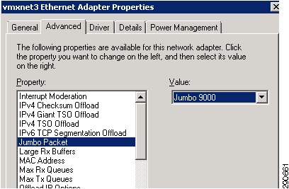
Guest Operating System Networking
Using the VMXNET3 paravirtualized network adapter will yield the best performance for virtualized SharePoint 2010 deployments.
See "Guest OS Network Best Practices" (http://www.vmware.com/pdf/Perf_Best_Practices_vSphere4.1.pdf) on page 33.
Three requirements exist to take advantage of the VMXNET3:
•
•
•
Figure 15 VMXNET Guest Adapter Settings
Traffic Isolation
Traffic isolation was implemented in accordance with best practices for Cisco, NetApp, VMware, and Microsoft SharePoint 2010 per recommendations in the base FlexPod CVD. VLANs are created for the following traffic categories. These VLANs are assigned to the vNIC Templates within UCS and allow server administrators to use preconfigured traffic isolation:
•
•
•
•
•
•
•
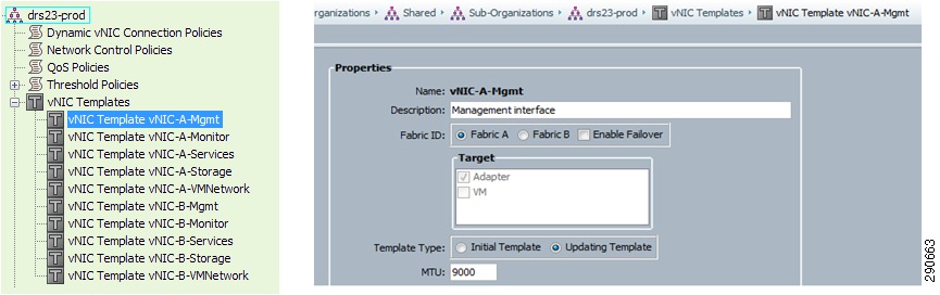
M81KR (Palo) Network Interface
UCS manager allows network administrators to create and configure all M81KR network settings to ensure quick and consistent adapter configuration for every ESXi deployment. This highlights the value of a single distribution point for server deployment within the UCS model. Server administrators can rely on these preconfigured templates for vNIC uplink configuration, reducing ESXi deployment complexity. Another advantage of vNIC templates is the MTU settings for Jumbo Frames. Network administrators can ensure this value is set for all ESXi uplink vNIC by setting the correct value for your organization.
Figure 16 Service Profile vNIC Templates
Nexus 1010 and 1000v
Nexus 1010
Providing the support platform for the Cisco Nexus 1000V Virtual Supervisor Module (VSM), the Nexus 1010 also supports the Cisco Nexus 1000V Network Analysis Module (NAM) Virtual Service Blade to analyze conversational traffic between application tiers within the SharePoint 2010 farm. This helps identify any crawl, indexing, or SQL transaction bottle necks.
Because the Nexus 1010 is a dedicated hardware platform for the both the 1000v virtual supervisor module and the NAM virtual service blade, the virtual machine processing overhead for the NAM and VSMs are removed from the ESXi hosts.
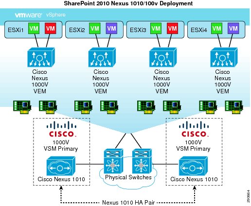
In this deployment the Nexus 1010 was deployed in a HA configuration as follows:
•
•
•
Figure 17 Nexus 1010 HA Pair with Redundant 1000v VSMs
When deploying a Nexus 1010 HA solution, ensure failover is working properly before deploying any virtual supervisor modules. Each pair deployment requires a unique domain ID; this includes VSMs. Cisco recommends Nexus 1010 and Nexus 1000V VSMs in redundant pairs.
Details around the recommended best practice for Nexus 1010 can be found in the Cisco Nexus 1010 Virtual Services Appliance Deployment Guide (http://www.cisco.com/en/US/prod/collateral/switches/ps9441/ps9902/white_paper_c07-603623.html).
Nexus 1000V and Virtual Machine Networking
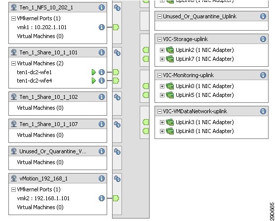
Nexus 1000V provides two key profile types for deployment within vCenter for use with virtual machines. vEthernet port-profiles are used to define a common set of network configuration commands for multiple interfaces tied to virtual machines. Ethernet (Uplink) port-profiles are used for physical uplinks from the ESXi servers themselves.
Network administrators are capable of provisioning all port-profiles to include appropriate VLANs, ACLs, Port Channel settings, QOS, Port Security, and Port mirroring. Figure 18 shows examples of both the vEthernet port-profiles and the Ethernet (Uplink) port-profiles.
Figure 18 vEthernet and Ethernet Port Profiles in vCenter
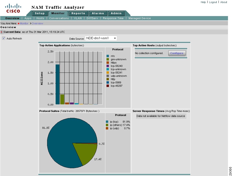
NAM Reporting from Nexus 1000V
With the Nexus 1000V Network Analysis Module (NAM) virtual service blade administrators can audit network policy compliance with the upstream switches and ensure network policy enforcement. NAM presents a visibility layer to administrators for traffic analysis and SharePoint 2010 performance monitoring. SharePoint 2010 WAAS optimization traffic is also available though NAM. Real-time, historical, and health statics are also available for review when any SharePoint issue arises, speeding time to resolution. When deployoing NAM on the Nexus 1010, ensure the VSM is created on the active node of the 1010 HA pair.
How to Create NAM virtual instance in N1K as primary
N1010-1# conf tN1010-1(config)# virtual-service-blade NAMN1010-1(config-vsb-config)# virtual-service-blade-type new nam-4-2-1.isoN1010-1(config-vsb-config)# interface data vlan 140N1010-1(config-vsb-config)# enable primaryFor more information, see Cisco Prime Network Analysis Module (NAM) for Nexus 1010 (http://www.cisco.com/en/US/products/ps10846/index.html).
Figure 19 Nexus 1010 VSB NAM Top Active Applications
Storage
Setting up NetApp Storage
For this deployment a pair of 3270s are installed in the data center. The arrays are equipped with 22x600GB SAS 10K drives in each of the DS4243 shelves. Always follow NetApp and VMware best practices when configuring storage for SharePoint 2010 on FlexPod for VMware.
For more information, see:
•
•
Figure 20 FlexPod for VMware Storage Connectivity
Fibre-Channel Storage Area Network
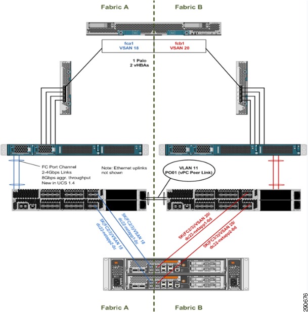
Fibre channel is used in this deployment for the purpose of stateless computing and direct LUN access for the virtualized SQL cluster servers. The environment is set up according to Figure 21.
Figure 21 Fibre-Channel Storage Area Network Configuration
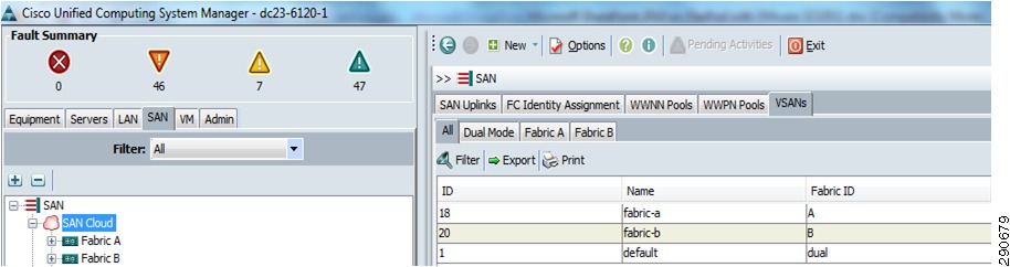
Soft Zoning and VSAN
Within in USC manager, two separate VSANs are created—VSAN 18 on Fabric A and VSAN 20 on Fabric B.
Figure 22 UCS Manager VSAN Configuration
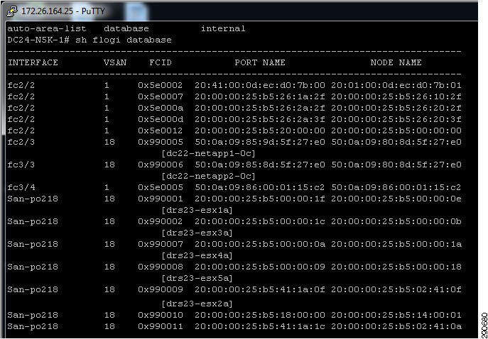
These same VSANs are created on the Nexus 5000 and are used in conjunction with Zones and Zonesets to define access boundaries for storage targets and LUN masking at the array level.
In Figure 23 we can see the device alias logged into fabric A Nexus 5000 using a show flogi database command.
Figure 23 Nexus 5000 Flogi Database Information for Device Alias
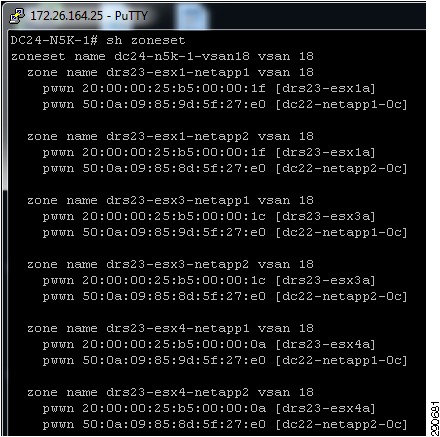
Sample design Zoneset information is provided in Figure 24. It is best practice to configure Zones with a single initiator single target configuration as shown in Figure 24.
Figure 24 Nexus 5000 Zoneset and Zone information
For additional zoning and VSAN information, see http://www.cisco.com/en/US/docs/switches/datacenter/nexus5000/sw/configuration/guide/cli/FCintf.html.
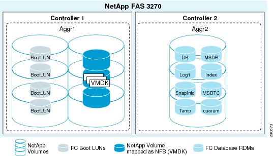
Storage Layout
Aggregate configuration consists of 16 disk RAID groups with 11 drives assigned. The SharePoint 2010 volumes are allocated based on load distribution across the 3270 controllers.
Figure 25 SharePoint 2010 Storage
Storage Virtualization
VMFS is a cluster file system that provides storage virtualization optimized for virtual machines. Each virtual machine is encapsulated in a small set of files and VMFS is the default storage system for these files on physical SCSI disks and partitions. VMware supports Fibre-Channel, iSCSI, and NAS shared storage protocols.
It is preferable to deploy virtual machine files on shared storage to take advantage of VMware VMotion, VMware High Availability™ (HA), and VMware Distributed Resource Scheduler™ (DRS). This is considered a best practice for mission-critical deployments, which are often installed on third-party, shared storage management solutions.
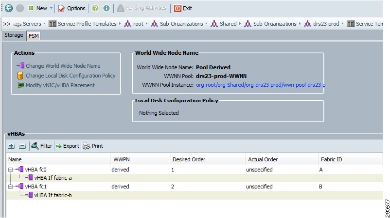
UCS Service Profile Templates and Storage
One portion of the UCS service profile template is the vHBA configuration for the M81KR. This allows storage administrators to pre-configure WWNN and WWPN pools for consistency and predictability when deploying ESXi using service profile templates.
Figure 26 Service Profile Templates for WWNNs and WWPNs
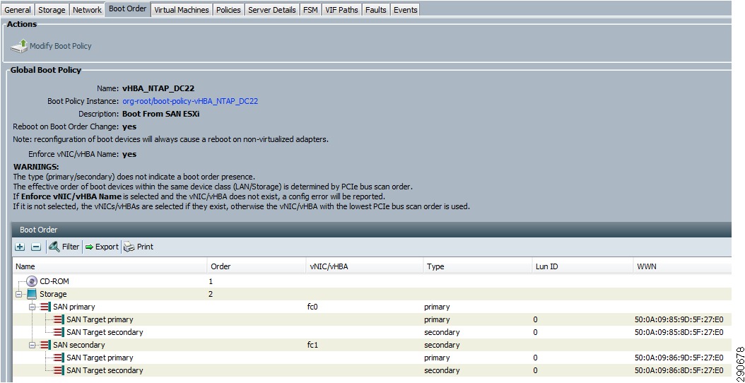
UCS manager also allow for stateless computing configuration from service profile template using global boot polices. This feature offers service profile mobility from one server to another within the system. The new server can boot from the exact same operating system image providing increased availability. An example boot policy configuration is provided in Figure 27.
Figure 27 Boot Policy SAN Target Configuration
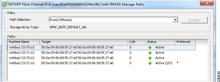
Storage Multipathing
VMware recommends you set up a minimum of four paths from an ESX host to a storage array, which means the host requires at least two HBA ports. Review the path information with vCenter for verification of correct mulitpathing.
Figure 28 vCenter LUN Path Verification
Raw Device Mapping
VMFS also supports Raw Device Mapping (RDM). RDM allows a virtual machine to directly access a volume on the physical storage subsystem and can only be used with Fibre Channel or iSCSI. RDM can be thought of as providing a symbolic link from a VMFS volume to a raw volume. The mapping makes volumes appear as files in a VMFS volume. The mapping file, not the raw volume, is referenced in the virtual machine configuration. For a more complete discussion, consult the VMware SAN System Design and Deployment Guide.
It is also possible and even advantageous in some circumstances to mix VMFS and RDM in SharePoint environments under the following conditions:
•
•
•
•
•
•
•
•
•
Virtualizing MSCS Clustering for Microsoft SQL 2008 R2
Database virtualization gives administrator the opportunity to take advantage of application clustering, while maintaining consolidation, portability, and host availability. These key features integrate well with FlexPod for VMware and SharePoint 2010 Enterprise designs.
Initial Configuration of VM Cluster Pair
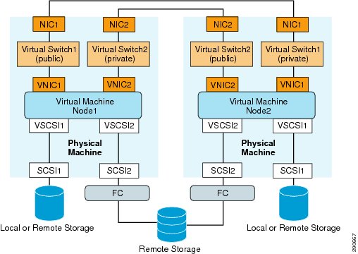
The initial VM was deployed from the same template as all the other SharePoint 2010 farm servers. There are a number of requirements for running a Microsoft cluster on VMware.
•
•
•
•
Figure 29 VMware MSCS Overview
The first cluster disk should be created manually and presented on a separate SCSI controller. This RDM LUN should be presented to the VM in physical compatibility mode. Ensure the SCSI Bus Sharing is set to Physical.
The second VM follows the same procedure but using the existing RDM LUN. The device node should be same as the first virtual machines shared storage disks (for example, SCSI (1:0)). At this point you can simply attach the quorum disk from the location of the first node. The Microsoft cluster service can now be installed. Address any issues discovered during the cluster validation and testing.
MSCS HA and DRS Considerations
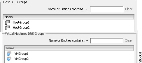
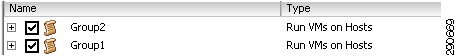
Ensure that VM-VM anti-affinity DRS rules are created and set correctly to separate the virtual machine cluster nodes. In addition, VM-Host affinity rules are required because HA does not obey VM-VM affinity rules. VMware HA might put clustered virtual machines on the same host. Create separate virtual machine groups for each cluster node. In this design we used VMgroup1 for MSCS node1 and VMgroup2 for MSCS node2. Then two host groups were created for the ESXi hosts running the nodes. HostGroup1 and HostGroup2. Finally, a "Must run on Hosts in Group" rule was added to the DRS rule set.
Figure 30 Host and Virtual Machines DRS Groups
Figure 31 DRS Host Rules
SnapDrive Install 6.3
As part of the MSCS installation, NetApp SnapDrive is utilized to automate several provisioning tasks when using RDM LUNs. The initial iGroup for RDM LUN mapping should be created during the setup of the initial shared disk when Microsoft cluster was created. SnapDrive 6.3P2_x64 was installed for this deployment. SnapDrive has the follow requirements:
•
•
•
•
•
•
•
Once the new LUNS are created for your SharePoint 2010 database environment, ensure cluster failover is working properly and that you can manage the disk from SnapDrive on each node when active. See the SnapDrive® 6.3 for Windows Installation and Administration Guide for additional information regarding SnapDrive and its configuration and implementation.
When creating new RDM LUNs you can select manual iGroup selection to avoid creating redundant iGroup with random names.
SQL install on Cluster
As part of the SQL 2008 R2 installation a Microsoft Distributed Transaction Coordinator cluster service was created. Also ensure the following prerequisites are meet.
•
•
•
•
Refer to Before Installing Failover Clustering SQL Server 2008 R2 (http://msdn.microsoft.com/en-us/library/ms189910.aspx).
Cisco ACE and SharePoint 2010 Architecture
Cisco ACE module features utilized in this SharePoint 2010 design include:
•
•
•
•
•
•
•
•
For detailed information on these ACE features, visit the Cisco ACE site (http://www.cisco.com/en/US/products/ps6906/index.html).
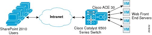
Figure 32 Cisco ACE Load Balances Client Requests across Multiple WFEs
ACE Configuration
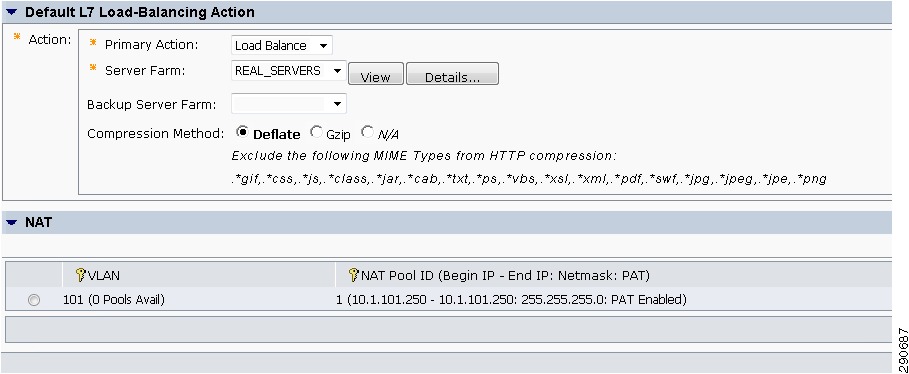
The ACE context in this design used probe configuration for the SharePoint 2010 application and WFE servers. These were generic ICMP requests and TCP probes for the central administration application port. Real servers were added to server farms and assigned where the probe configuration was applied. The predictors "least connections" was assigned based on specific load balancing requirements.
For additional information about ACE configuration options, see Cisco ACE Application Control Engine Module (http://www.cisco.com/en/US/products/ps6906/index.html).
Figure 33 ANM ACE L7 Configuration Settings
ANM
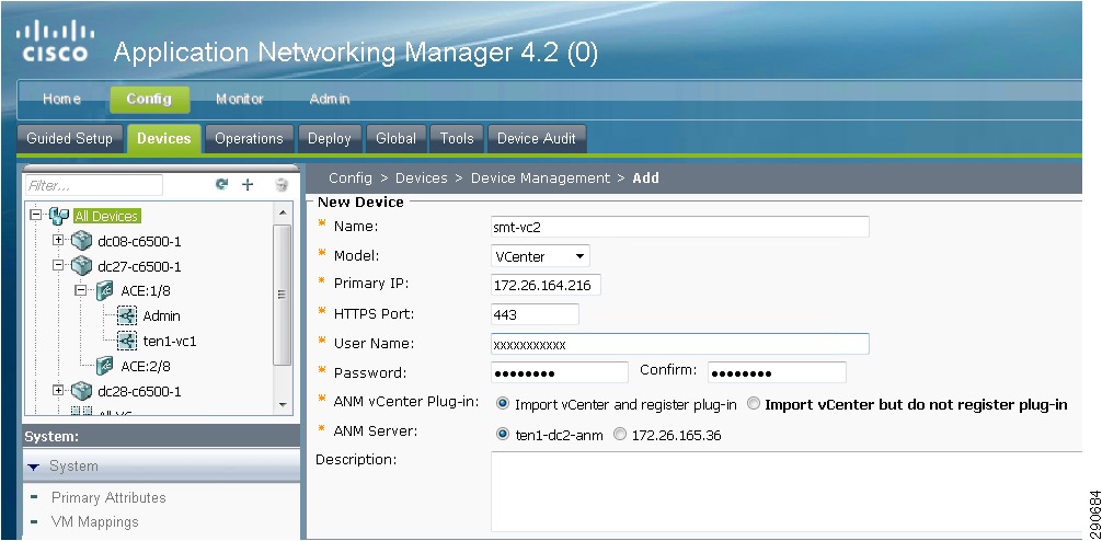
Cisco Application Networking Manager simplifies maintenance of Layer 4-Layer 7 virtualized network devices and services by providing a single management interface for administrators to implement, monitor, and configure content service modules such as ACE devices. ANM 4.2 can be deployed with a downloadable anm-va-4.2.ova directly into vCenter.
Figure 34 Application Networking Manager vCenter Integration
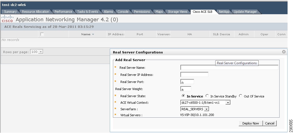
ANM can be used to import device for guided setup. This include a new feature that allows vCenter to be added as a device, adding VMs directly from vCenter to the Server farm as additional Real Servers for load balancing, and topology mapping of VMs defined in a load-balanced server farm.
Figure 35 vCenter Application Networking Manager Adding New VM as Real Server
Figure 36 vCenter ANM VM Load Balancing Topology Map
Branch and WAN and SharePoint 2010
WAAS Setup between Branch and Data Center
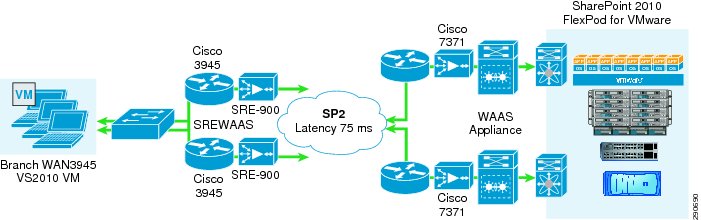
Using a highly available service provider WAN link, traffic traverses the "preferred" router. If the primary router becomes unavailable, branch users still have an alternate path to access SharePoint content. Two Cisco 3945s are deployed in this model with SRE modules running WAAS 4.3.1. Branch Layer 2 switches connect the SREs to the LAN segment.
Figure 37 WAAS Setup Between Branch and Data Center
WAAS Setup for Remote User to Data Center
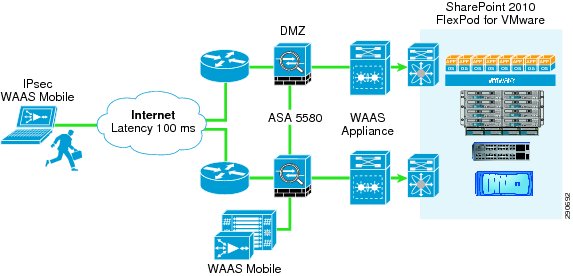
When a remote client connects to the VPN and gains access to corporate resources, the WAAS Mobile client is automatically enabled and the traffic is optimized. During validation, we simulated a cable user who can do 384 kbps upstream and 7mbps downstream with 100 MS latency. With the default out-of-box configuration, WAAS Mobile sever is able optimize VPN overhead, HTTP, HTTPS, and other TCP-based applications, such as RDP.
Figure 38 WAAS Setup for Remote User to Data Center
Solution Validation
Testing Methodology
The testing methodology was a multi-phased approach to achieve specific environment service levels. Following recommendations from Microsoft for SharePoint 2010 sizing and capacity, an evaluation period using a smaller workload was a baseline for scaling. Using a typical process for enterprise deployment planning is essential to achieve a successful virtualized application infrastructure. The benefits of SharePoint 2010 on FlexPod for VMware is validated using Visual Studio 2010 and Visual Test Agents to generate loads on the environment and show a successful 50000 user workload across multiple SharePoint 2010 features sets. To achieve this goal, we randomly selected users from a 5000 user pool for each test cycle. Site randomization and document selection was also randomized. Cache control and "ParseDependentRequests" property for all tests was set to false. Cache settings for a Web application (SharePoint Server 2010) (http://technet.microsoft.com/en-us/library/cc770229.aspx) were configured.
Test and Measurement Tools
We ran Microsoft Visual Studio Ultimate 2010 (http://www.microsoft.com/visualstudio/en-us/products/2010-editions/ultimate) and Test Load Agent on four systems to simulate Web requests from SharePoint users. The workload mixture consisted of the following SharePoint areas:
•
•
•
•
•
•
These workloads were then run in against specific test criteria and broken into the follow categories:
•
•
•
•
During these test we examined CPU/memory utilization, requests per second, and page response time. Our functional goal was to achieve 80% utilization, approximately 84 total requests per second, and less than a three second page response time. A two minute warm up period was run before each test. The testing was functionally successful, meeting the criteria set to achieve a 50000 user workload with approximately 10% concurrency.
Requests per second (RPS) are the number of requests for information each server is capable of responding to per second. Within a page, there are numerous components which create one or more requests. The amount of requests a farm can handle is a common measurement of load.
The environment was scaled to six WFEs at the end of testing with ~320 RPS to confirm further scaling. At this ratio, the SQL database CPU became over 85% utilized. This configuration ratio is approaching the limits of a four CPU SQL database bottleneck. Each user was targeted with a utilization of 60 requests per hour. Each response per second of throughput supports 60 simultaneous users and 600 total users.
Data Center SharePoint on FlexPod
Validating SharePoint Server Performance
Configuring CPU and Memory on SharePoint VMs
Initial CPU and memory configurations were based on the evaluation deployment and then service scaled for 84 requests per second, average page response of less than three seconds, and CPU and memory utilization of less than 80 percent. CPU and memory configuration for SharePoint 2010 are directly dependent on services and feature utilization.
VMware VMotion/DRS Validation
The same SharePoint 2010 functional workload sets were running during the load balancing and availability test.
Validating With VMware HA
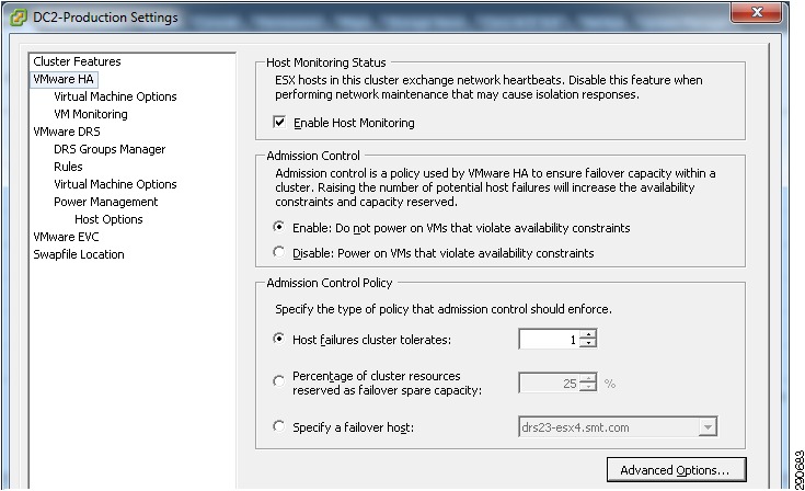
VMware HA was configured per Figure 39. Additional advanced HA setting were das.failuredetectiontime and two das.isolationaddress entries. Virtual machine restart priority was default and host isolation response was set to power off.
Figure 39 VMware HA Settings
The test was completed by simulating a power failure of a blade within the UCS chassis. The VMs on the failed host were restarted successfully and distributed among the remaining hosts in the cluster.
VMware DRS Validation
VMware Distributed Resource Scheduler was utilized a number of times during the validation phase. For a CPU loaded test of DRS, an artificial imbalance was created with VMs being placed on only three hosts. Once load was generated, the imbalanced triggered a DRS recommendation and migrated the VMs to the appropriate host to load balance the cluster resource utilization. Cisco ACE was also used to balance user connections and was not impacted by this migration.
Validating UCS Service Profiles
During the high availability test, a UCS blade had a simulated power failure. The service profile was disassociated with the failed blade and associated with a new blade. The stateless model used in this deployment highlights the availability of the UCS solution. An addition to this availability scenario, UCS has the capability to quickly assign more powerful blades to the service profile for immediate scalability. With a stateless deployment model, UCS gives an additional option of pre-provisioning blades to be put in use as demand grows.
NetApp FAS 3270 Controllers
NetApp stats were monitored from the console using a systat command. These statistics were taken during the workload testing at a one second interval to ensure the storage system never exceeded 80% CPU utilization.
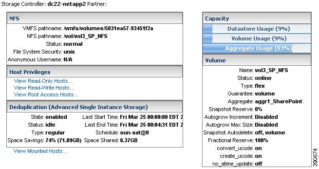
NFS Datastore (Validation)
All WFE and Application VMs deployed in this solution are put on an NFS share being presented from the NetApp CAN and provisioned using the NetApp VSC vCenter plug-in.
There are space savings of 74% for the VMDK volume.
Figure 40 Detail Volume Information from VSC
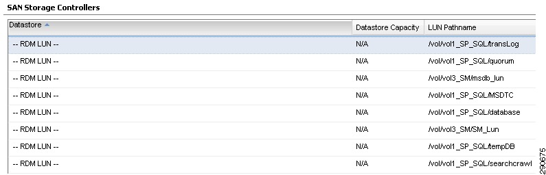
MSCS Database and Log LUNs
The database VMs are deployed on FC/VMFS LUNs with RDMs attached to database virtual machines.
Figure 41 MSCS Database and Log LUN information
SQL Failover Testing
To simulate a cluster failure, the active cluster node was powered off. The passive cluster node took ~1 minute to continue servicing SharePoint 2010 user request.
Cisco ACE and SharePoint 2010 Validation
Validating ACE and ANM
Load balancing and optimization of traffic is a crucial part of a successful SharePoint 2010 deployment. The Cisco ACE component provides additional availability and scalability for SharePoint service implementations. Currently ACE and ANM integrate directly with VMware vCenter to provide simplistic management of load-balanced virtual server farms.
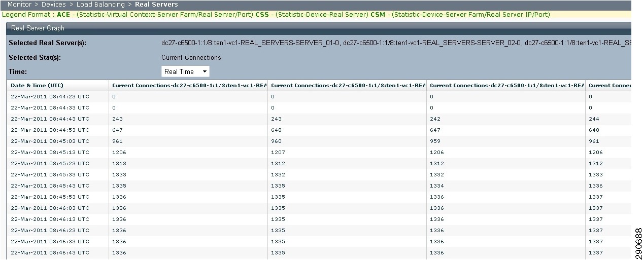
ACE Validation
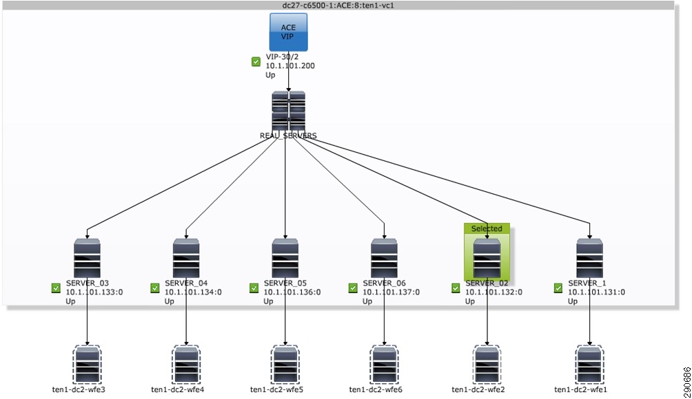
The Application Control Engine was validated by ensuring balanced request connections and CPU utilization of the WFE servers. Figure 42 shows balanced current connection counts to all Web front end servers.
Figure 42 SharePoint 2010 Scaling Workload ACE Current Connections
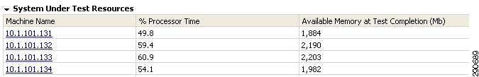
During the load balacing testing the CPU utlization across the WFE virtual was fairly consistent as shown in Figure 43.
Figure 43 SharePoint 2010 CPU Utilization During Load Test
Branch and WAN and SharePoint 2010 Validation
WAAS Performance Results
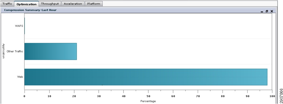
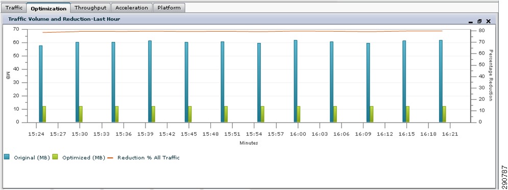
The WAAS branch test consisted of a scaled-down workload. Testing was validated using WAAS central and Netflow traffic optimization statistics. Figure 44 and Figure 45 contain compression and reduction information after WAAS implementation. We can see a very high Web traffic compression ratio and an 80% traffic reduction ratio.
Figure 44 WAAS Branch Compression Summary
Figure 45 Traffic Volume Reduction
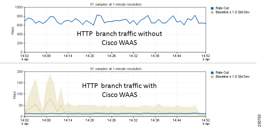
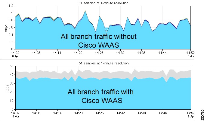
Figure 46 and Figure 47 show pre- and post-WAAS implementation optimization statistics. We can see significant HTTP traffic optimization and a large improvement in the bandwidth available to all traffic.
Figure 46 HTTP Branch Traffic Optmization
Figure 47 All Branch Traffic Optmization
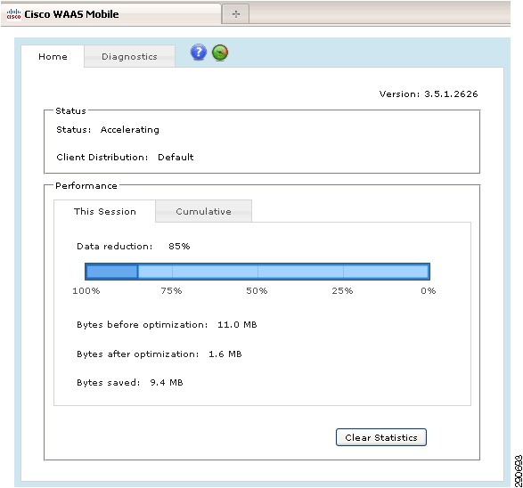
WAAS Mobile Performance Results
The WAAS branch test consisted of a scaled-down workload. In addition to the data reduction shown in Figure 48, a manual response test was conducted for page load times and document upload and download with a noticeable improvement in both.
Figure 48 WAAS Mobile Optimization Sample
Conclusion
Most customers are done with the first phase of the cloud journey (30% virtualized data center), that is, virtualizing non mission-critical applications such as infrastructure applications,s, transient workload etc. The big challenge for customers to move beyond 30% virtualized data centers is to virtualize Tier-1 enterprise apps such as SharePoint, Exchange, SQL Server, etc.
The major inhibitors for customers to virtualize Tier-1 enterprise applications include lack of proven shared virtual infrastructure stacks and concerns about ISV support.
The detailed solution architecture and validation presented in this CVD highlights Microsoft SharePoint 2010 virtualization candidacy with the desired performance and efficiency:
•
•
In addition, the solution highlighted in this CVD provides many benefits to SharePoint application owners and end users accessing data locally or remotely:
•
•
•
•
Note
Bill of Materials
Software
References
•
http://technet.microsoft.com/en-us/sharepoint/ee263917•
http://www.cisco.com/en/US/netsol/ns944/index.html•
http://www.vmware.com/products/vsphere/overview.html•
http://www.netapp.com/us/products/storage-systems/•
http://www.cisco.com/en/US/products/ps5680/Products_Sub_Category_Home.html•
http://www.cisco.com/en/US/products/ps6906/index.html•
http://www.cisco.com/en/US/products/ps9441/Products_Sub_Category_Home.html•
http://www.cisco.com/en/US/docs/solutions/Enterprise/Data_Center/Virtualization/flexpod_vmware.html•
http://www.cisco.com/en/US/prod/collateral/switches/ps9441/ps9902/white_paper_c07-603623.html•
http://www.cisco.com/en/US/docs/switches/datacenter/nexus5000/sw/configuration/guide/cli/CLIConfigurationGuide.html•
http://www.cisco.com/en/US/products/ps10846/index.html•
http://www.netapp.com/us/library/technical-reports/tr-3298.html•
http://media.netapp.com/documents/tr-3749.pdf•
http://www.vmware.com/pdf/Perf_Best_Practices_vSphere4.1.pdf•
http://www.vmware.com/pdf/vsphere4/r41/vsp_41_resource_mgmt.pdf•
http://www.microsoft.com/visualstudio/en-us/products/2010-editions/ultimateMicrosoft TechNet Articles
•
http://technet.microsoft.com/en-us/library/ff758647.aspx•
http://technet.microsoft.com/en-us/library/cc770229.aspx•
http://msdn.microsoft.com/en-us/library/ms189910.aspx•
http://technet.microsoft.com/en-us/sharepoint/ee263917Appendix—ACE SharePoint 2010 Context Configuration
access-list ANYONE line 10 extended permit ip any anyaccess-list everyone line 16 extended permit icmp any anyprobe icmp PINGinterval 2passdetect interval 60rserver host SERVER_02ip address 10.1.101.132inservicerserver host SERVER_03ip address 10.1.101.133inservicerserver host SERVER_04ip address 10.1.101.134inservicerserver host SERVER_05ip address 10.1.101.136inservicerserver host SERVER_06ip address 10.1.101.137inservicerserver host SERVER_1ip address 10.1.101.131probe PINGinserviceserverfarm host REAL_SERVERSpredictor leastconnsprobe PINGinband-health check remove 500 resume-service 300rserver SERVER_02inservicerserver SERVER_03inservicerserver SERVER_04inservicerserver SERVER_05probe PINGinservicerserver SERVER_06inservicerserver SERVER_1probe PINGinserviceclass-map match-all VIP-302 match virtual-address 10.1.101.200 anypolicy-map type management first-match REMOTE_MGTclass class-defaultpermitpolicy-map type loadbalance first-match SLB_LOGICclass class-defaultserverfarm REAL_SERVERScompress default-method deflatepolicy-map multi-match CLIENT_VIPSclass VIP-30loadbalance vip inserviceloadbalance policy SLB_LOGICloadbalance vip icmp-reply activenat dynamic 1 vlan 101interface vlan 101description Servers vlanip address 10.1.101.253 255.255.255.128access-group input ANYONEnat-pool 1 10.1.101.250 10.1.101.250 netmask 255.255.255.0 patservice-policy input CLIENT_VIPSno shutdown