Downloads |
Table Of Contents
Service Module Design with ACE and FWSM
Bridged versus Routed Mode on ACE and FWSM
Inline versus One-Arm Server Load Balancing
VLAN Extension for Bridged Design
VLAN Extension for the VRF Routed Design
RHI and Next Hop Propagation with OSPF
VRF Routed Design Traffic Flows
VRF Routed Design and Loop-Free Access
Server-to-Server Load Balancing
Service Module VLAN Assignment
Inter-Switch Link (ISL) Configuration
VRF Routed Design Configuration Notes
Service Module Design with ACE and FWSM
This document describes the deployment of virtual services into the server farm using a modular approach. The goal is to easily produce the right mix of routing, switching, security, and application delivery services as required. Here an approach is shown for delivering these services using virtual contexts on the Firewall Services Module (FWSM) and Application Control Engine (ACE) as well as Virtual Routing and Forwarding (VRF) instances on the Catalyst 6500. It describes a way to deploy these services together in a high availability environment.
Contents
Overview
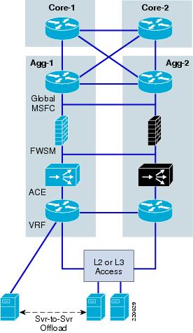
Figure 1 shows the overall topology and the components used here. There is a core, aggregation, and access tier to represent a typical server farm. The aggregation switches are equipped from north to south with the global Multilayer Switch Feature Card (MSFC), Firewall Services Module (FWSM), Application Control Engine (ACE), and VPN routing and forwarding (VRF) instance.
The access switch connects to the aggregation switch over various topologies: Layer 2 looped, Layer 2 loop-free, or Layer 3 links. An additional link from the VRF is shown to indicate the ability to support Layer 3 routed connections between servers without traversing the service modules.
Figure 1 Data Center Topology
With the use of virtual ACE and FWSM contexts, virtual LANs, and virtual routers, a pair of aggregation switches in the data center can support multiple customer environments simultaneously. These virtual services can be added into a given scenario without the need to purchase new hardware, cabling, switching, and so on. An ACE context can be deployed for server load balancing (SLB), Secure Socket Layer (SSL), or security. FWSM can also be used with ACE for a more robust security feature set. VRFs provide inter-subnet routing behind the firewall so that a given security domain does not have to be confined to a single subnet. Here all the services are deployed in-line, forming a chain of services tailored to the needs of a particular application or customer.
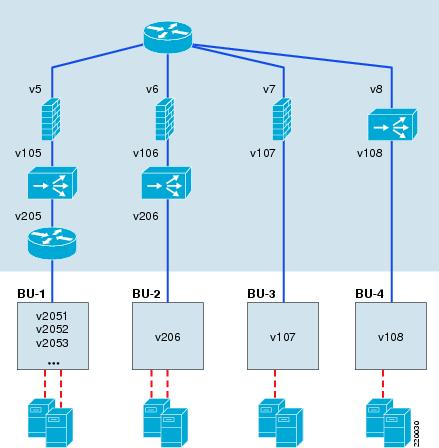
Figure 2 shows an example of an aggregation switch supporting four business units, each using a different mix of services:
•
BU-1 requires security, application delivery, and Layer 3 routing in the access.
•
•
•
This document describes how to deploy the first two of these scenarios: a "VRF routed" design using FWSM, ACE, and VRF; and a "bridged" design using FWSM and ACE. These names are somewhat arbitrary in that bridging technology is used in each. In both designs, the ACE and FWSM contexts are deployed in bridged mode. However, for the purpose of discussion, the service chain with a VRF is referred to as the "VRF routed" design, and the service chain without the VRF is referred to as a "bridged" design.
Figure 2 Multiple Service Chains within a Single Aggregation Switch
These two designs are presented as follows:
•
•
•
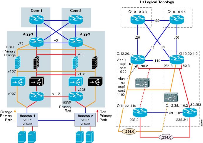
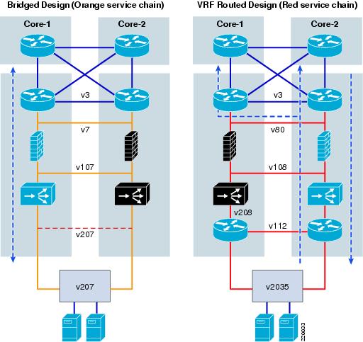
Figure 3 shows the details of the two service chains as they were created in the lab. Note that by using virtual contexts and VRFs, an "Active-Active" design is achieved where both aggregation switches (AGG-1 and AGG-2) can be used actively for forwarding and backup. From the point of view of a given service chain, the solution is Active/Standby failover. With the presence of multiple service chains and the alternating of Active/Standby roles, the Active/Active failover solution is achieved. Figure 3 shows a physical and logical view of the designs, with the orange primary path on the left and red primary path on the right. The Layer 3 topology is shown on the right to clarify some of the show commands and configurations that are used throughout this document. The network numbers shown are abbreviated, just showing the third octet. The prefix, not shown, is 12.20. The one exception to the 12.20 prefix is the inter-VRF link, which is 12.38.110.0. The dashed lines show the connections blocked by inactive FWSM/ACE contexts. (The active contexts are not shown on the right.) The Open Shortest Path First (OSPF) Protocol router IDs are shown in blue.
Figure 3 Lab with Two Service Chains—Bridged and VRF Routed Designs
Design Choices
When deploying these services, there are a number of choices to make, including:
•
•
•
•
•
•
•
The following sections describe some of the considerations taken into account when making these choices.
Bridged versus Routed Access
Here the distinction of bridging versus routing toward the access refers to where the router is deployed in the aggregation switch (not to be confused with Layer 3 in the access switch itself). The bridged design leaves all of the routing to the global MSFC. The VRF routed design adds a VRF south of the service modules to do the access layer routing. This is useful when there is a requirement to route between subnets behind the firewall. For example, NAS storage resources might be located on a different subnet than the web server, but within the same security domain. Forcing these flows through the firewall reduces the overall capacity, without providing any additional security.
Another option is to place the firewall context above the global MSFC, between the aggregation and core tiers. This approach, however, is undesirable for a number of reasons. STP processes are introduced into the core of the network, the MSFC loses direct visibility to link failures, and the regular changes to FWSM contexts are potentially disruptive to the entire network. Alternatively, when dedicated VRFs are used to provide routing functionality, the integrity of the core is maintained, while maximum flexibility is provided for access connections. VRFs can also provide a way to manage overlapping address space without the need for Network Address Translation (NAT).
Figure 3 illustrates these two design options coexisting together independently in the same aggregation switch pair: a "red" service chain with a VRF providing the default gateway function, and an "orange" service chain where the global MSFC is the default gateway and the access is bridged to it across the FWSM and ACE contexts. The red environment uses OSPF routing to advertise the red subnets from the VRF to the core. The orange subnet is directly connected to the global MSFC. The advantage of the orange service chain is simplicity. The red service chain is more complex, but is better suited to environments with multiple subnets and heavy traffic flows within the same security domain.
Bridged versus Routed Mode on ACE and FWSM
Both ACE and the FWSM can be deployed in either bridged or routed mode. Bridged mode is selected here to simplify the Layer 3 topology. Consider the following when making this choice:
•
•
•
•
Inline versus One-Arm Server Load Balancing
To protect resources, firewalls are always deployed inline. With the SLB device, there is a choice. It can also be placed in one-arm mode where it is only inline for load balanced flows and direct server traffic bypasses it altogether. In this case, both ACE and FWSM are deployed inline. This provides a migration path for integrating security functions onto ACE and a simpler SLB topology. With security built-in, ACE can potentially eliminate the need for FWSM. However, currently there are enough gaps to warrant the use of a separate firewall product. Fixup support, object grouping, integration with MARS and Cisco Security Manager are examples of capabilities that might be required of a firewall, but that are not yet present in ACE. By deploying ACE and FWSM contexts together inline, either module is positioned for security. Currently, FWSM contexts can be deployed, and as ACE software improves to include a more comprehensive feature set, these functions can be migrated with minimal architectural impact. This way, ACE, which has up to three times the capacity of the FWSM, can be used to lengthen the lifecycle of the security solution.
From an SLB perspective, inline deployment also has the advantage of simplicity because the VIP is directly in the path between clients and servers. Although one-arm mode improves performance by offloading non-load-balanced traffic, there is additional complexity because either source NAT or policy-based routing (PBR) must be used to ensure the return flow of traffic. Source NAT might not be a good fit for customers that are using the source IP address to track client usage patterns. PBR avoids this problem but adds other considerations, such as routing complexity, asymmetrical routing for non-load-balanced flows, and VRF support; PBR is not available on VRFs.
For more information on the one-arm solution for the CSM, see the following URL: http://www.cisco.com/en/US/solutions/ns340/ns517/ns224/ns304/net_design_guidance0900aecd8010e7a8.pdf.
VLAN Extension
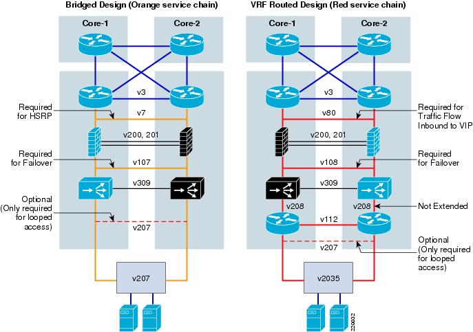
Figure 4 highlights which VLANs need to be extended for each design. In both designs, the Layer 3 VLANs (v3 and v112) are extended for OSPF routing updates. Failover VLANs are also extended for FWSM (v200 and v201) and ACE (v309). The VLANs between the service modules and the access layer vary somewhat as explained in the following sections.
Figure 4 VLAN Extension
VLAN Extension for Bridged Design
In the bridged design, the orange chain shows VLAN7 and VLAN107 extended, while for VLAN207, extension is optional, depending on whether looped access is required. VLAN7 is extended for HSRP because in this configuration the global MSFC is the default gateway for the servers. Each MSFC needs to see the HSRP keepalives across VLAN7 to know which should be active. VLAN107 is extended so that in the case of an FWSM or ACE context failure, where FWSM is active on one side and ACE is active on the other, the traffic is not blocked.
Note
ACE BPDU forwarding:
access-list BPDU ethertype permit bpduinterface VLAN107bridge-group 1access-group input BPDUinterface VLAN207bridge-group 1access-group input BPDUFWSM BPDU forwarding:
access-list BPDU ethertype permit bpduaccess-group BPDU in interface insideaccess-group BPDU in interface outsideVLAN207 is optional. For a looped access design, VLAN207 is extended and STP is relied on to prevent loops in the access. If loop-free access is required, VLAN207 is not extended and ACE VLAN tracking is used to recover from link failures. For more information on tracking, refer to Failover Overview.
VLAN Extension for the VRF Routed Design
In the VRF routed design, VLAN80 and VLAN108 are extended, VLAN208 is split, and VLAN2035 is optional.
•
•
•
•
RHI and Next Hop Propagation with OSPF
Route Health Injection (RHI) provides a way to dynamically advertise the VIP address without manually configuring static routes in the MSFC. RHI injects a route into the routing table when the multimatch policy map on ACE is configured using the advertise or advertise active command (the active keyword removes the route if all the servers are unavailable). If ACE needs to propagate this route across an FWSM, as is the case in this design, the ip route inject command is also required on the interface adjacent to the routing instance.
policy-map multi-match vserver-configurationclass virtual-ip-addressloadbalance vip inserviceloadbalance policy serverfarm-and-predictorloadbalance vip icmp-replyloadbalance vip advertise activeinterface VLAN108service-policy input vserver-configurationip route inject VLAN80After the local MSFC receives the static route to the VIP via RHI, a routing protocol is typically used to advertise this route to the other aggregation MSFC. The way this route is propagated by OSPF, which was used here, is important to understand when considering which links should be extended. In testing the two design scenarios, it was observed that the bridged design behaved differently from the VRF routed design.
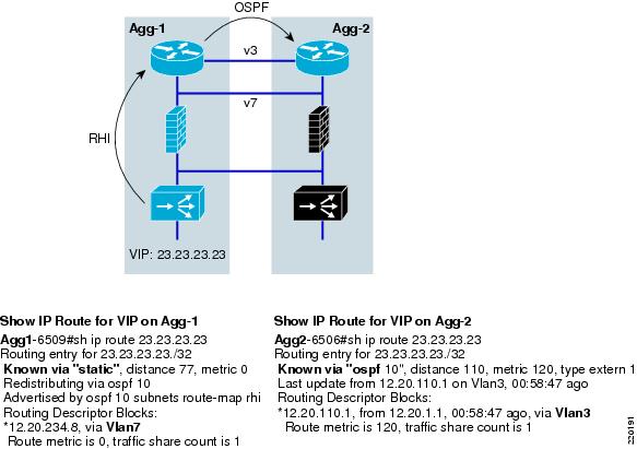
With the bridged design, RHI injects the VIP route into AGG-1, the primary router, where it appears as a static route pointing at VLAN 7 to get to the VIP. Then, after OSPF propagates the route, AGG-2 sees the path as originating from VLAN 3, which is how it learned about it from AGG-1. This is shown in Figure 5.
Figure 5 RHI and OSPF Behavior with the Bridged Design
This is not surprising. AGG-1 sees the path to the VIP via the local VLAN7 and AGG-2 sees it via VLAN3 where it learned it. What we learned though was that this behavior depended on VLAN7's passive interface status. As shown in the following OSPF configuration, VLAN7 is defined by default as a passive-interface in OSPF.
router ospf 10redistribute static subnets route-map rhipassive-interface defaultno passive-interface VLAN3no passive-interface VLAN80no passive-interface TenGigabitEthernet4/1no passive-interface TenGigabitEthernet4/2no passive-interface TenGigabitEthernet4/4Testing showed that when the interface is not passive, AGG-2 no longer views the next hop as via VLAN3 but from VLAN7, the access VLAN. When the interface is non-passive, OSPF builds its database with this in mind, not recognizing that the VLAN might not be extended across the trunk. This is a minor point in the bridged design because VLAN7 needs to be extended for HSRP. If AGG-2 gets a message for the VIP it will send it to VLAN7 where it will be forwarded down to ACE-1.
In the VRF routed design the access VLAN, VLAN80, cannot be passive because routing updates must be exchanged between the VRF and the global MSFC. Here AGG-2 receives the RHI route for VIP 12.20.100.81 (ACE is primary in AGG-2 for the red chain) and OSPF redistributes it to its neighbors. Note that now both routers see the path to the VIP via VLAN80, as shown in Table 1.
This means that VLAN80 must be extended for the VRF routed design or traffic to the VIP that traverses the AGG-1 MSFC is blackholed. This is noted because it would be desirable to keep the access VLAN, VLAN80, split (pruned from the ISL trunk) so that the traffic flow can be optimized. When VLAN80 is extended, you cannot control which path outbound traffic will take because now the active VRF will see both the AGG-1 and AGG-2 global MSFCs as equal-cost neighbors on the same VLAN. As a result, some outbound traffic will have to flow across the ISL link and create additional bandwidth requirements between the switches. The bridged design does not have this problem because outbound traffic is always sent to the active HSRP router.
Traffic Flows
When creating an Active/Active failover environment, a goal is to minimize Inter-Switch Link Protocol (ISL) traffic wherever possible. ISL links are limited in bandwidth compared to the overall backplane of the switch and should be used sparingly. To avoid potential bottlenecks, it would be better if the links between the aggregation switches were used by actual data traffic only when necessary for failover scenarios. The blue arrows in Figure 6 show the normal traffic flows for the two scenarios.
Figure 6 Traffic Flow
Bridged Design Traffic Flows
The orange flow is entirely on the side of the primary ACE and FWSM contexts. Outbound traffic from the servers has only one path to the active HSRP router, straight up AGG-1. Inbound traffic to the VIP also goes directly to AGG-1 via the core because OSPF advertises a better path via AGG-1 (providing the VLAN7 interfaces are configured as passive, as shown in previous examples).
The only special configuration required is for inbound traffic to the server real addresses. This could go either direction by default. It can be optimized by tuning down the OSPF cost (the default cost of a VLAN interface is 1000, which can be viewed by using the show ip ospf interface command) of VLAN7 on AGG-1.
interface VLAN7ip ospf cost 900This causes all server-direct traffic to go directly to AGG-1 from the core.
VRF Routed Design Traffic Flows
The red flow can be kept inline for inbound traffic to the VIP and real addresses by increasing the cost of VLAN80 on AGG-1.
interface VLAN80ip ospf cost 1100Because VLAN80 cannot be split with OSPF, as previously described, outbound traffic will be balanced across both aggregation routers. The primary red VRF will see both AGG-1 and AGG-2 as neighbors on the same network and equal cost paths to the default route. As a result, the VRF routed design requires bandwidth on the aggregation ISL links for normal data traffic.
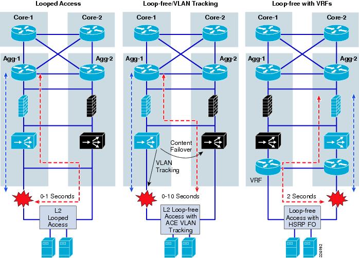
Access Design
Although a spanning-tree network can be built reliably, many customers continue to have an interest in building networks with loop-free topologies, to eliminate any possibility of looping. The ACE tracking features can help in building a loop-free access design, although currently there is an issue with extended failover times, described in more detail below. First, consider two of the reasons for looped access in the server farm: server clusters and service modules.
Server Clusters
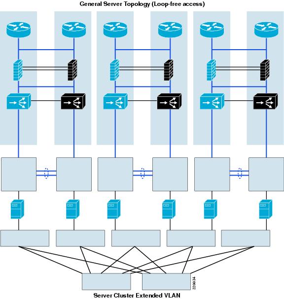
One reason for a looped access topology is the requirement for Layer 2 adjacency between servers in a cluster. If all of the servers can be placed in a single access switch or two adjacent (U topology) switches, this is not a problem, but if the VLAN needs to span more than two switches, the only way to get there is looped access. With a looped access topology there is no limitation on the number of access switches containing the same VLAN.
Another approach to dealing with Layer 2 adjacent server clusters is to dedicate a separate looped VLAN just for them that terminates on its own "out of band" mini-aggregation tier. Then, any server with a cluster requirement will have a dedicated NIC that attaches to this network. As shown in Figure 7, in the event of a spanning tree loop on this network, the impact is limited to servers on the cluster VLAN and does not affect the overall data center.
Figure 7 Server Cluster Design Option
Looped Access with FWSM
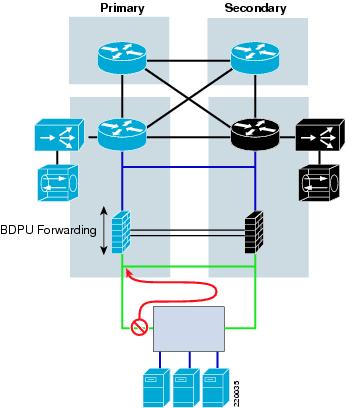
Typically, FWSM designs in the aggregation tier have mandated a looped topology in the access layer, where an ISL link between the two aggregation switches creates a loop, as shown in Figure 8.
If there is a link failure on the primary link to the access layer, the traffic has a secondary path via AGG-2, but without the ISL link, it runs into a dormant firewall context that is unable to pass the traffic. An alternative to creating this loop in the access is for the FWSM to track the failure in the access and move the active context over to AGG-2 where the traffic has been redirected. This does not work very well with the FWSM because the FWSM is unable to track HSRP and VLAN autostate events such as the ACE module. It is able to detect when an FWSM interface becomes unreachable, but this process takes 50 seconds, which is much longer than the typical client timeout. In addition, each FWSM context is not in its own failover group as is the case with ACE. Thus, failover of one context moves over other contexts that might not need to be moved. The best way to get fast convergence for access link failures with an FWSM is looped access. With looped access and rapid PVST+, convergence is extremely fast, in the range of 0-1 seconds.
Note
Figure 8 Looped Access with FWSM
Loop-Free Access with ACE
ACE, with its auto-state awareness and tracking mechanisms, is able to rapidly initiate context failovers on events other than a module failure. ACE can track VLANs, HSRP groups, and designated IP addresses. By associating the health of an access-link to the failover of the context, ACE provides loop-free access in the presence of service modules. Figure 9 shows a "bridged design" service deployment with ACE deployed south of the FWSM. This figure also shows that the server VLAN of the ACE context has a single port. When the link fails, auto-state notifies ACE that the VLAN is down because there are no longer any active ports besides ACE itself. ACE can track this event to initiate a failover. As a result, when the primary link fails, ACE opens up the rest of the path so that traffic can pass back up to the primary HSRP router. This requires an ISL hop when there is a FWSM in the path.
The ACE tracking mechanism for VLANs is extremely fast. When the link fails, the ACE context fails over instantly and the outage is less than a second in duration. Currently, however, there is an issue (documented in CSCsf96889) associated with the preempt mechanism that makes the primary context active again when the link is reestablished, resulting in outages ranging from 5-10 seconds. This was tested with the U design with two access switches interconnected. The access switch with the primary uplink saw outages up to five seconds with preempt where the other access switch was consistently in the 8-10 second range.
Figure 9 Failover Behavior with Different Access Scenarios
VRF Routed Design and Loop-Free Access
Unlike service modules that use an Active/Standby failover mode, VRFs are always active and ready to forward traffic. As shown in the third scenario in Figure 9, when a Layer 3 path is available between the VRFs, a Layer 2 loop in the access can be avoided when HSRP converges. When loop-free access is configured this way, the gating factor is the time it takes HSRP to converge to the new active VRF serving as the default gateway. Using the default timers of HSRP, convergence takes place in 7-9 seconds. With the hello and hold timers set to 1/3, there is convergence within two seconds, which is not quite as fast as Rapid PVST+ and looped access, but close.
interface VLAN2034ip vrf forwarding redip address 12.20.234.2 255.255.255.0standby 1 ip 12.20.234.1standby 1 timers 1 3standby 1 priority 110standby 1 preemptServer-to-Server Load Balancing
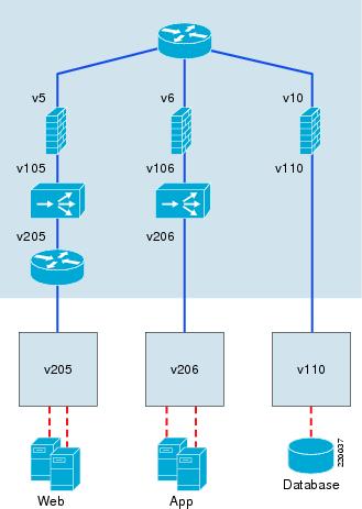
In addition to client-server load-balanced connections, there are also cases when servers need to originate load-balanced connections. An example is when a web server needs to reach an application server in a tiered environment. When the web tier and application tier are on different service chains, this works the same as any client-to-server load-balanced flow because the return traffic must come back to the global MSFC to be routed (see Figure 10 for an example).
Figure 10 Server-to-Server SLB with Tiered Application Design
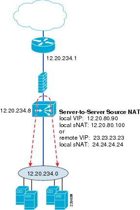
However, when the servers are both on the same side of the ACE context, special configurations are required to ensure that the traffic traverses the ACE symmetrically. Without source NAT or policy-based routing (PBR), the destination real server will return traffic directly to the originating server, bypassing the ACE and breaking the connection. For the "VRF routed design" and "bridged design" approaches described here, PBR is not an option; it is not available on VRFs and does not apply to Layer 2 connections within a VLAN. As a result, source NAT is the only way to get the return traffic back to ACE. While source NAT is often a problem for customers gathering data on client addresses on the Internet, for server-to-server connections, this is probably less of an issue.
Figure 11 shows an example of a "bridged design" deployment. The MSFC has a VLAN interface on the 12.20.234.0 subnet and everything below it is also in that subnet, the management interfaces of FWSM and ACE, and the servers. The VIP will generally need to be different from the VIP for client connections because source NAT is tied to the VIP; all traffic destined for this VIP will use source NAT. Therefore, if you do not want the client traffic to use source NAT, you will need a dedicated VIP for the server-to-server flows. Otherwise, there are no restrictions on the use of the VIP and source NAT address.
ACE intercepts all messages directed to the VIP or source NAT address, regardless of whether they are in the local subnet. Even when the server is sending to the MAC address of the MSFC as its default gateway, ACE intercepts these packets, based on the Layer 3 address knowing that it owns the VIP and the source NAT address. As a result, it is not necessary to configure RHI or static routes in the MSFC to handle traffic to VIPs or source NAT addresses outside of the local subnet range.
Figure 11 Source NAT for Server-to-Server Load Balancing
The source NAT configuration is best done with a dedicated VIP that is then added to the existing multi-match policy map along with the external VIP, as shown in the following example. In this example, the VIP 12.20.234.100 is used for server-to-server load-balanced connections. The nat dynamic command is attached to it in the multi-match policy map. Note that the source NAT address is identified on the actual interface that the traffic is expected to be seen on, in this case, the server-side VLAN, VLAN207.
class-map match-all external-vip2 match virtual-address 22.22.22.22 anyclass-map match-all source-nat-vip-12.20.234.1002 match virtual-address 12.20.234.100 anypolicy-map type loadbalance first-match basic-slbclass class-defaultserverfarm FARM1policy-map multi-match aggregate-slb-policyclass external-viploadbalance vip inserviceloadbalance policy basic-slbloadbalance vip advertise activeclass source-nat-vip-12.20.234.100loadbalance vip inserviceloadbalance policy basic-slbloadbalance vip advertise activenat dynamic 123 VLAN207interface VLAN107description "Client-side Interface"bridge-group 1access-group input BPDUaccess-group input anyoneservice-policy input aggregate-slb-policyip route inject VLAN 7interface VLAN207description "Server-side Interface"bridge-group 1access-group input BPDUaccess-group input anyonenat-pool 123 12.20.234.101 12.20.234.101 netmask 255.255.255.255 patservice-policy input aggregate-slb-policyThe connection table shows a server 12.20.234.16 sending to the server-to-server VIP 12.20.234.100. Then it shows it is load-balanced to 12.20.234.183, returning the traffic to 12.20.234.101, which is the address for source NAT, as identified in the NAT-pool.
switch/orange# show conntotal current connections : 4conn-id np dir proto VLAN source destination state----------+--+---+-----+----+---------------------+---------------------+------+96 1 in TCP 207 12.20.234.16:1673 12.20.234.100:80 ESTAB97 1 out TCP 207 12.20.234.183:8080 12.20.234.101:1037 ESTABThe VRF scenario is similar, except that the VIP and source NAT address cannot be on the same subnet as the servers. If not directly connected, the VRF must have a route to the VIP or source NAT address, either through RHI or a static route. RHI will propagate a route to a VRF with Cisco IOS Release 12.2(18)SXF5.
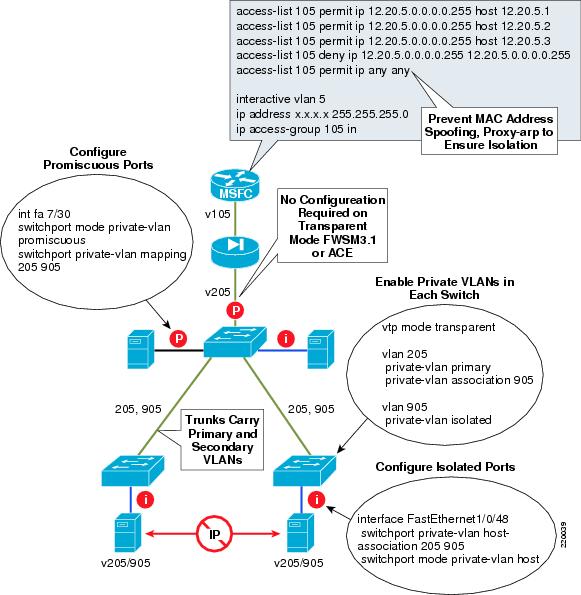
Private VLANs
Private VLANs work with ACE and FWSM 3.1 (bridged mode) transparently; there is no configuration required on the ACE or FWSM module. The ACE or FWSM port interfacing the access layer appears as a promiscuous port of the private VLAN. Some customers are interested in the ability to support filtered flows between isolated ports on a private VLAN. This is accomplished by enabling local proxy arp on the MSFC and creating the appropriate ACL. FWSM supports this functionality, ACE does not. Figure 12 provides an example.
Figure 12 Private VLAN Configuration
General Configuration Notes
This section summarizes the configurations of the various components using the bridged design as an example. The Catalyst configurations, including service module VLAN assignment, access configuration, ISL configuration, the ACE and FWSM configurations, and a detailed section on failover are provided. VRF Routed Design Configuration Notes covers the remaining configuration components that are specific to the VRF routed design.
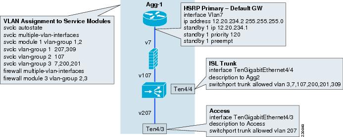
Service Module VLAN Assignment
Figure 13 shows how the VLANs are assigned to the service modules. In this case FWSM will need VLAN7, 107, 200 and 201. ACE will need VLAN107, 207, and 309. Because both service modules need VLAN107, three SVCLC groups are created. Group 1 is specific to ACE, Group 3 is specific to FWSM and Group 2 is common to both. The svclc autostate command is necessary for ACE to track the loss of an access link.
Access Configuration
VLAN7 is configured as an interface on the MSFC with HSRP primary on AGG-1. It is the default gateway for the servers.
Ten4/3 is the trunk to the access, and in this case VLAN207 is assigned only to it. Note that this trunk appearance is the only instance of VLAN207 besides ACE itself on the Catalyst 6500. As a result, the loss of this access link will create an autostate event that ACE can track for failover. If VLAN207 was placed on other access links, the loss of a single link would not cause the VLAN to go down. If VLAN207 appeared on another port, it would probably indicate a looped design, so a loop-free design with this approach is restricted to a single access switch per VLAN, or two access switches with the U design shown in Figure 9.
Inter-Switch Link (ISL) Configuration
Ten4/4 is the trunk between the two aggregation switches and the following VLANs are extended across the link.
VLAN3: L3 link between Agg-1 and Agg-2 MSFCsVLAN7: Access VLAN on MSFCsVLAN107: Intermediate VLAN between FWSM and ACE contextsVLAN200 and 201: FWSM ft and state VLANsVLAN309: ACE ft VLANFigure 13 Catalyst Switch Configurations
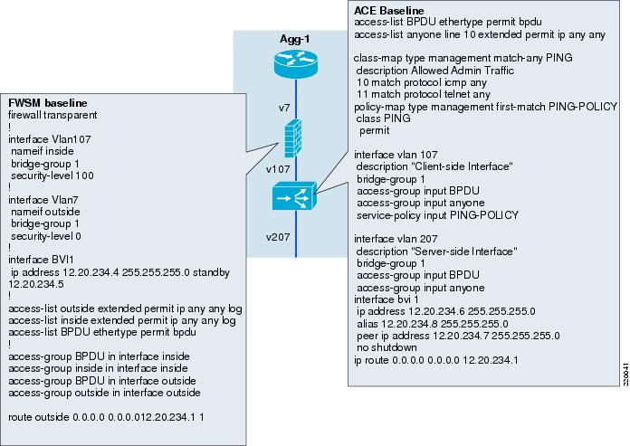
Figure 14 shows the minimum baseline configurations required to get started with the FWSM and the ACE modules, ACLs are wide open and SLB is not configured. As shown in the figure, both the FWSM and ACE contexts are configured with an ACL to permit BPDU forwarding. This is essential with VLAN7 and VLAN107 extended because if an Active/Active failover scenario occurred with either ACE or FWSM, looping would be prevented using STP. Without BPDU forwarding enabled, a simple misconfiguration, such as deleting the failover VLANs from the ISL, will create a loop.
Figure 14 Service Module Context Configurations
The ACL and bridge-group configuration is very similar between the ACE and the FWSM, except for the following differences:
•
•
•
Failover Overview
Table 2 lists some things to keep in mind about FWSM and ACE when it comes to failover.
FWSM Failover Configuration
Whichever mode is used, the configuration of bridge-mode ACE and FWSM contexts is mostly the same, they are simply bridging the traffic, applying ACLs, load-balancing rules, and SSL termination, as needed. The main difference is the connection to the access. Because the orange ACE touches the access directly, it will apply some networking intelligence to recover from access link failures, while the red ACE relies on the VRF for this functionality.
On the FWSM, the failover configuration is done on the system context. Note that the system context configurations on both FWSMs in the examples in Table 3 are identical, with the exception of the designation of the device as primary or secondary. The failover and state VLANs are defined, the polltime and holdtime are defined, the IP addresses of the primary and secondary are defined, preempt is enabled in this case, and failover group 1 and group 2 are designated as primary and secondary. The individual contexts are assigned to one of these failover groups: context red in group 2, context orange in group 1.
In the preceding examples, each user context needs to include its own address and the standby address in order for both sides to sync up, as follows:
•
interface BV11ip address 12.20.80.4 255.255.255.0 standby 12.20.80.5•
interface BV11ip address 12.20.234.4 255.255.255.0 standby 12.20.234.5The show failover command on the system context identifies which device it is, either primary or secondary, and it also shows the state of the failover groups (see Table 4). On the primary device, group 1 is shown to be active and group 2 as standby. On the secondary device, the opposite is true.
Entering the show fail command on the individual contexts displays the failover state for that individual context (see Table 5). In this example, the red context is in standby mode on the primary FWSM, while the orange context is active. The opposite is true of the secondary FWSM. Also, note that none of the interfaces are monitored. The FWSM can trigger a failover based on a monitored interface. The problem is it takes so long to discover the state of the interface, the feature is not of much use. ACE is much better suited for this task.
ACE Failover Configuration
The following ACE failover configuration is on the admin context, the combined equivalent of both the FWSM system and admin contexts. A FT VLAN interface is created which the heartbeats will traverse. The FT peer is where the heartbeat frequency is defined (for this example, every 100ms and 10 lost heartbeats to consider the peer lost). Each context is then associated with its own FT group where the priorities are set and preempt is configured. Preempt is defined under the FT group but does not show up here because it is enabled by default, unlike the FWSM where it is disabled by default.
ACE also requires each context to be in its own failover group. This is different from FWSM, which has only two failover groups. This provides an advantage because individual context failover behavior can be defined without impacting any other context. This feature also makes possible failover based on VLAN tracking. The context with the higher priority is always the active one, at least when preempt is enabled. The following configuration shows how priority is used to make orange primary on AGG-1 and red primary on AGG-2. Tracking, shown in the example, adjusts this priority value to failover a context.
ft interface VLAN 309ip address 12.20.39.1 255.255.255.0 ft group 2peer ip address 12.20.39.2 255.255.255.0 peer 1no shutdown no preemptpriority 210ft peer1 peer priority 200heartbeat interval 100 associate-context Adminheartbeat count 10 inserviceft interface VLAN 309ft group 8peer 1context orange priority 220allocate-interface VLAN107 peer priority 200allocate-interface VLAN207 associate-context orangeinservicecontext redassociate-interface VLAN108 ft group 7associate-interface VLAN208 peer 1priority 200peer priority 250associate-context redinserviceMost of the configuration is done on the primary (primary on the admin context) ACE module, only a few things need to be defined on the secondary, as shown in the following example. The FT interface is defined with the addresses reversed. The FT peer is configured the same, and the FT group for the admin context is configured with the priorities reversed. With the FT VLAN up this is enough for the ACE modules to sync up correctly and all of the rest of the configuration is copied over and the priority values are reversed.
VLAN Tracking
ACE can track the status of a VLAN, HSRP group, or IP address and failover a context when the state changes. Here the feature is used to enable loop-free Layer 2 access designs. To failover a link based on VLAN status there are three requirements.
•
•
•
switch/orange# show run ftGenerating configuration....ft track interface orangetrack-interface VLAN207peer track-interface VLAN207priority 100peer priority 100This configuration instructs the ACE to decrement its priority by 100 if VLAN207 goes down. The status is summarized with the show ft track detail command. If VLAN7 goes down, this context, which is currently active with a net priority of 220, will have a new priority of 120 and the standby context (which has priority 200) will become active.
switch/orange# show ft track detailFT Group : 8Status : in-serviceMaintenance mode : MAINT_MODE_OFFMy State : FSM_FT_STATE_ACTIVEMy Config Priority : 220My Net Priority : 220My Preempt : EnabledContext Name : orangeContext Id : 4Track type : TRACK_INTFVLAN Id : 207State : TRACK_UPPriority : 100Transitions : 1Failover Example
If the access link with VLAN207 fails, autostate informs ACE that the VLAN interface is down, and traffic will reroute as shown in Figure 9. To see an example, ping traffic is established from a remote host, 12.20.235.186 to a VIP of 23.23.23.23 on the orange context, which is active on AGG-1. A look at ACE-1 shows that the connection is established. Traffic comes inbound to the ACE on VLAN107 with a source IP of 12.20.235.186 and a destination of 23.23.23.23. It is load-balanced to the server at 12.20.234.183, which sends the traffic back to the original source, 12.20.235.186.
switch/orange# show conn | i ICMP47 1 in ICMP 107 12.20.235.186:27671 23.23.23.23:204858 1 out ICMP 207 12.20.234.183:27671 12.20.235.186:0Next, the access link from AGG-1 to Access-1 is failed by shutting down the port on Access-1. The ICMP traffic is sent at a rate of 10/sec drops 20 packets for a two second outage as ACE fails over. The ACE-1 console indicates the failover by disabling configuration mode as follows:
NOTE: Configuration mode has been disabled on all sessions.On ACE-1 when entering the show ft track detail command, note that the net priority is now 120, and the state is hot standby rather than active. The track state also shows a down condition:
switch/orange# show ft track detailFT Group : 8Status : in-serviceMaintenance mode : MAINT_MODE_OFFMy State : FSM_FT_STATE_STANDBY_HOTMy Config Priority : 220My Net Priority : 120My Preempt : EnabledContext Name : orangeContext Id : 4Track type : TRACK_INTFVLAN Id : 207State : TRACK_DOWNPriority : 100Transitions : 4The FWSM is still active on AGG-1:
FWSM/orange# show failFailover OnLast Failover at: 09:45:35 PST Aug 22 2006This context: ActiveActive time: 692833 (sec)Interface inside (12.20.234.4): Normal (Not-Monitored)Interface outside (12.20.234.4): Normal (Not-Monitored)Peer context: Standby ReadyActive time: 110 (sec)Interface inside (12.20.234.5): Normal (Not-Monitored)Interface outside (12.20.234.5): Normal (Not-Monitored)AGG-1 is still the active HSRP router:
AGG-1-6509# show stand VLAN7VLAN7 - Group 1Local state is Active, priority 120, may preemptHellotime 3 sec, holdtime 10 secNext hello sent in 0.636Virtual IP address is 12.20.234.1 configuredActive router is localStandby router is 12.20.234.3 expires in 7.620Virtual mac address is 0000.0c07.ac012 state changes, last state change 1w1dIP redundancy name is "hsrp-Vl7-1" (default)From the standpoint of ISL link utilization, it would be ideal if the entire traffic flow stayed on AGG-2 in this failover state, but there is currently no way to map FWSM failover behavior to ACE failover behavior, so the traffic comes up through the Access-2 link through ACE-2, then across the VLAN107 ISL to AGG-1, through FWSM-1, to MSFC-1 which is still the active HSRP router. For Active/Active failover deployments, the ISL bandwidth must be provisioned to account for the load resulting from a failover scenario.
Note
ACE2 after failover:
switch/orange# show conn | i ICMP50 1 in ICMP 107 12.20.235.186:27671 23.23.23.23:204864 1 out ICMP 207 12.20.234.181:27671 12.20.235.186:0Without sticky configured, ACE, by default, load balances each new ICMP connection in a round-robin fashion. With the failover condition, ACE retains the round-robin order and establishes the flow to the next server in rotation when it arrives at the standby context.
Preempt Behavior
With the initial failover and VLAN tracking, ACE fails over immediately with a two second traffic outage and the pings are load-balanced onto the next real server in rotation. However, with preempt enabled, the effect on traffic is somewhat more disruptive on the return path. When the link comes back there is a 30-50 second delay before preempt begins and the context fails back to ACE-1, at which point there is a 5-10 second outage before traffic resumes. Until this issue (documented in CSCsf96889) is resolved, this must be factored into the decision to use looped access.
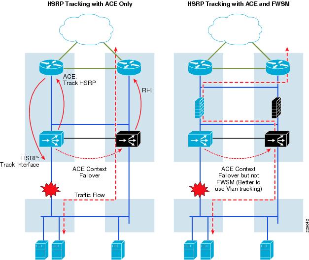
HSRP Tracking
Another approach is to have HSRP track the interface and ACE track the HSRP group. The goal is to align the path along the secondary route, minimizing ISL use. If the FWSM context is inline this is counter-productive. It actually doubles ISL usage because the active FWSM is still on AGG-1, causing the outbound traffic to bounce from ACE-2 to FWSM-1 and then back to AGG-2 MSFC. VLAN tracking would be preferable, as shown in Figure 15.
With an ACE-only scenario, all traffic is aligned on AGG-2. Outbound traffic flows up through ACE-2 and because HSRP is also active on AGG-2, it heads straight up.
Figure 15 HSRP Tracking
Inbound traffic is also aligned through AGG-2 because of RHI. When ACE-1 fails over due to the access link failure, it stops advertising the VIP (in this example, 23.23.23.23). ACE-2, now active, begins advertising it. The result is shown in the following examples in the before and after look at the AGG-1 and AGG-2 routing table for 23.23.23.23.
In the first example, the routing table for AGG-1 is shown when ACE-1 (the ACE on AGG-1) is active. The second example shows the routing table for AGG-1 when ACE-1 has failed and ACE-2 (the ACE on AGG-2) is active. The metrics show why traffic from the core is routed directly from the core to AGG-1 when ACE-1 is active and routed directly to AGG-2 when ACE-1 fails.
When ACE-1, the primary ACE for the orange context, is active on AGG-1, it shows a metric of zero via the local VLAN to ACE-VLAN 7. This way, the core routers send VIP-destined traffic directly to AGG-1 when ACE-1 is active. When ACE-1 fails and no longer advertises the route to the VIP via RHI into AGG-1, ACE-2 becomes active and uses RHI to inject the route into AGG-2. As a result, following ACE failover, AGG-1 shows a higher metric of 120 via OSPF. This way, the core routers upstream see AGG-2 as the better path and forward traffic directly to it. This is good because traffic follows the AGG switch with the active ACE, minimizing the use of ISL between AGG-1 and AGG-2.
AGG-1 Routing Table when ACE-1 is Active
AGG-1-6509# show ip route 23.23.23.23Routing entry for 23.23.23.23/32Known via "static," distance 77, metric 0Redistributing via ospf 10Advertised by ospf 10 subnets route-map rhiRouting Descriptor Blocks:* 12.20.234.8, via VLAN7Route metric is 0, traffic share count is 1AGG-1 Routing Table when ACE-2 is Active
AGG-1-6509# show ip route 23.23.23.23Routing entry for 23.23.23.23/32Known via "ospf 10," distance 110, metric 120, type extern 1Last update from 12.20.1.10.2 on VLAN3, 00:00:30 agoRouting Descriptor Blocks:* 12.20.110.2, from 12.20.1.2, 00:00:30 ago, via VLAN3Route metric is 120, traffic share count is 1The next two examples simply show that the reverse is true on AGG-2. AGG-2 shows a cost of zero to the VIP when ACE-2 is active and a higher cost when ACE-1 is active.
AGG-2 Routing Table when ACE-1 is Active
AGG-1-6506# show ip route 23.23.23.23Routing entry for 23.23.23.23/32Known via "ospf 10," distance 110, metric 120, type extern 1Last update from 12.20.1.10.1 on VLAN3, 00:00:54 agoRouting Descriptor Blocks:* 12.20.110.1, from 12.20.1.1, 00:00:54 ago, via VLAN3Route metric is 120, traffic share count is 1AGG-2 Routing Table when ACE-2 is Active
AGG-1-6509# show ip route 23.23.23.23Routing entry for 23.23.23.23/32Known via "static," distance 77, metric 0Redistributing via ospf 10Advertised by ospf 10 subnets route-map rhiRouting Descriptor Blocks:* 12.20.234.8, via VLAN7Route metric is 0, traffic share count is 1Thus, when ACE-1 is active, the AGG-1 MSFC has the lower metric. AGG-1 learns about the VIP from RHI and it becomes "known via static" from VLAN7, and the next hop address is the ACE BVI alias (12.20.234.8). AGG-2's metric is higher because it learns about it only indirectly via OSPF. This information is propagated up into the core routers and their routing tables point to AGG-1 as the preferred path to the VIP. As shown, when ACE-2 becomes active, the routing is reversed and AGG-2 becomes the preferred path.
Using HSRP Tracking
To configure HSRP tracking, first HSRP must be configured to track the interface. The HSRP group also needs to be given a name for ACE to refer to. One thing to note is that ACE tracks only VLAN interfaces and HSRP tracks only physical interfaces, so while ACE referred to the state of VLAN207 on the ten4/3 access link, HSRP refers to the Ten4/3 link itself.
interface VLAN7ip address 12.20.234.2 255.255.255.0standby 1 ip 12.20.234.1standby 1 timers 1 3standby 1 priority 120standby 1 preemptstandby 1 name ACEstandby 1 track TenGigabitEthernet4/3The ACE tracking configuration is similar to VLAN tracking configuration, except that it now refers to the HSRP group as given by the standby name shown in the example, ACE.
ft track hsrp access-trunktrack-hsrp ACEpeer track-hsrp ACEpriority 100peer priority 100VRF Routed Design Configuration Notes
The VRF routed design shown above in Figure 3 adds a VRF below the transparent FWSM and ACE modules. In this example, OSPF is the routing protocol and the relevant components of the routing configuration in AGG-1 are shown here:
ip vrf redrd 100:6router ospf 40 vrf redlog-adjacency-changesauto-cost reference-bandwidth 1000000timers throttle spf 1000 1000 1000redistribute static subnetspassive-interface VLAN2035network 11.20.0.0 0.0.255.255 area 30network 12.20.0.0 0.0.255.255 area 30network 12.38.110.0 0.0.0.255 area 30router ospf 10log-adjacency-changesauto-cost reference-bandwidth 1000000timers throttle spf 1000 1000 1000redistribute static subnets route-map rhipassive-interface defaultno passive-interface VLAN3no passive-interface VLAN80no passive-interface TenGigabitEthernet4/1no passive-interface TenGigabitEthernet4/2network 12.20.20.0 0.0.0.255 area 30network 12.20.41.0 0.0.0.255 area 30network 12.20.80.0 0.0.0.255 area 30network 12.20.110.0 0.0.0.255 area 30network 12.20.234.0 0.0.0.255 area 30arp vrf red 12.20.80.2 0000.0000.0080 ARPAarp 12.20.80.252 0000.0000.0208 ARPAroute-map rhi permit 10match ip address 11set metric-type type-1access-list 11 permit 23.23.23.23access-list 11 permit 12.20.0.0 0.0.255.255Interface Configurations
interface TenGigabitEthernet4/1description to Core 1ip address 12.20.20.2 255.255.255.0no ip redirectsno ip proxy-arpip pim sparse-dense-modeip ospf message-digest-key 1 md5 C1sC0!ip ospf network point-to-pointip ospf hello-interval 2ip ospf dead-interval 6logging event link-statusspanning-tree guard loop!interface TenGigabitEthernet4/2description to Core2ip address 12.20.41.2 255.255.255.0no ip redirectsno ip proxy-arpip pim sparse-dense-modeip ospf message-digest-key 1 md5 C1sC0!ip ospf network point-to-pointip ospf hello-interval 2ip ospf dead-interval 6logging event link-statusload-interval 30!interface TenGigabitEthernet4/4description to AGG-2switchportswitchport trunk encapsulation dot1qswitchport trunk native VLAN2switchport trunk allowed VLAN 3,6,7,10,15,25,60-62,80,90,106-110,112,160,161switchport trunk allowed VLAN add 200,201,206,209,300,309switchport mode trunkno ip addresslogging event link-statusload-interval 30!interface VLAN3description AGG-1_to_AGG-2_L3-RPbandwidth 10000000ip address 12.20.110.1 255.255.255.0no ip redirectsno ip proxy-arpip pim sparse-dense-modeip ospf authentication message-digestip ospf message-digest-key 1 md5 7 106D580A264753ip ospf network broadcastip ospf hello-interval 1ip ospf dead-interval 3logging event link-status!interface VLAN80mac-address 0000.0000.0080ip address 12.20.80.2 255.255.255.0no ip redirectsno ip proxy-arpip pim sparse-dense-modeip ospf authentication message-digestip ospf message-digest-key 1 md5 7 106D580A264753ip ospf cost 1100ip ospf hello-interval 1ip ospf dead-interval 3logging event link-status!interface VLAN208mac-address 0000.0000.0208ip vrf forwarding redip address 12.20.80.252 255.255.255.0no ip redirectsno ip proxy-arpip pim sparse-dense-modeip ospf authentication message-digestip ospf message-digest-key 1 md5 7 106D580A264753ip ospf hello-interval 1ip ospf dead-interval 3standby 1 timers 1 3standby 2 ip 12.20.80.251standby 2 priority 120standby 2 preempt delay minimum 180!interface VLAN7ip address 12.20.234.2 255.255.255.0ip ospf cost 900standby 1 ip 12.20.234.1standby 1 priority 120standby 1 preempt!interface VLAN2035ip vrf forwarding redip address 12.20.235.2 255.255.255.0no ip redirectsno ip unreachablesno ip proxy-arpip pim sparse-dense-modestandby 1 ip 12.20.235.1standby 1 priority 110standby 1 preemptKeep the following things in mind with regard to these configurations:
•
•
•
•
Adding a Service Chain
This section includes configuration examples for the end-to-end components that must be configured when adding a new chain of services. The "bridged design" orange chain is used in these examples.
•
AGG-1 and AGG-2VLAN7VLAN107VLAN207Access-1 and Access-2VLAN207•
svclc autostatesvclc multiple-VLAN-interfacessvclc module 1 VLAN-group 1,2svclc VLAN-group 1 104,204,207,205,208,300-310svclc VLAN-group 2 82,105,107,108svclc VLAN-group 3 5,6,7,10,18,80,106,110,180,182,200,201firewall multiple-VLAN-interfacesfirewall module 3 VLAN-group 2,3•
AGG-1Int ten4/3description to Accessswitchport trunk allowed VLAN add 207Int ten4/4description to AGG-2switchport trunk allowed VLAN add 107,207AGG-2Int ten4/3description to Accessswitchport trunk allowed VLAN add 207Int ten4/4description to AGG-1switchport trunk allowed VLAN add 107,207Access-1Int ten1/1Description to agg-1switchport trunk allowed VLAN add 207Int ten1/2Description to access-2switchport trunk allowed VLAN add 207Access-2Int ten1/1Description to agg-2switchport trunk allowed VLAN add 207Int ten1/2Description to access-1switchport trunk allowed VLAN add 207•
AGG-1interface VLAN7ip address 12.20.234.2 255.255.255.0standby 1 ip 12.20.234.1standby 1 priority 120standby 1 preemptstandby 1 name ACE2standby 1 track TenGigabitEthernet4/3no shutAGG-2interface VLAN7ip address 12.20.234.3 255.255.255.0standby 1 ip 12.20.234.1standby 1 priority 110standby 1 preemptstandby 1 name ACE2standby 1 track TenGigabitEthernet4/3no shut•
Access-1Int fa9/26Description 12.20.234.180 - R1Z-1switchport access VLAN207Int fa9/27Description 12.20.234.181 - R1Z-2switchport access VLAN207Int fa9/37description mcast-server1 12.20.234.16switchport access VLAN207Access-2Int fa9/6descr 12.20.234.183 R1Z-3switchport access VLAN207•
AGG-1 and AGG-2router ospf 10network 12.20.234.0 0.0.0.255 area 30•
context orangeallocate-interface VLAN7allocate-interface VLAN107config-url disk:/orange.cfgjoin-failover-group 1•
change to context orangefirewall transparenthostname orangedomain-name cisco.comenable password cisco encryptednames!interface VLAN7nameif outsidebridge-group 1security-level 0!interface VLAN107nameif insidebridge-group 1security-level 100!interface BVI1ip address 12.20.234.4 255.255.255.0 standby 12.20.234.5!passwd cisco encryptedaccess-list outside extended permit ip any any log infoaccess-list inside extended permit ip any any log infoaccess-list BPDU ethertype permit bpdupager lines 24logging enablelogging timestamplogging monitor debugginglogging buffered informationallogging trap informationallogging asdm informationallogging queue 0logging device-id hostnamelogging host outside 172.28.214.89mtu outside 1500mtu inside 1500icmp permit any outsideicmp permit any insidearp timeout 14400access-group BPDU in interface outsideaccess-group outside in interface outsideaccess-group BPDU in interface insideaccess-group inside in interface insideroute outside 0.0.0.0 0.0.0.0 12.20.234.1 1snmp-server enable traps snmp authentication linkup linkdown coldstarttelnet timeout 5ssh 0.0.0.0 0.0.0.0 insidessh time•
context orangeallocate-interface VLAN107allocate-interface VLAN207ft group 8peer 1preemptpriority 220peer priority 200associate-context orangeinservice•
change orangelogging enablelogging monitor 7access-list BPDU ethertype permit bpduaccess-list anyone line 10 extended permit ip any anyclass-map type management match-any PINGdescription Allowed Admin Traffic10 match protocol icmp any11 match protocol telnet anypolicy-map type management first-match PING-POLICYclass PINGpermitinterface VLAN107description "Client-side Interface"no ip addressbridge-group 1access-group input BPDUaccess-group input anyoneservice-policy input PING-POLICYno shutdowninterface VLAN207description "Server-side Interface"no ip addressbridge-group 1access-group input BPDUaccess-group input anyoneservice-policy input PING-POLICYno shutdowninterface bvi 1ip address 12.20.234.6 255.255.255.0alias 12.20.234.8 255.255.255.0peer ip address 12.20.234.7 255.255.255.0no shutdownip route 0.0.0.0 0.0.0.0 12.20.234.1•
Checkpoint create baseline•
probe http WEBSERVER-HEALTHCHECKport 8080request method get url /index.htmlexpect status 200 200rserver host red-180ip address 12.20.234.180inservicerserver host red-181ip address 12.20.234.181inservicerserver host red-183ip address 12.20.234.183inserviceserverfarm host FARM1probe WEBSERVER-HEALTHCHECKrserver red-180 8080inservicerserver red-181 8080inservicerserver red-183 8080inserviceclass-map match-all xyz-vip-20.20.20.20match virtual-address 20.20.20.20 tcp eq wwwpolicy-map type loadbalance first-match basic-slbclass class-defaultserverfarm FARM1policy-map multi-match aggregate-slb-policyclass xyz-vip-20.20.20.20loadbalance vip inserviceloadbalance policy basic-slbloadbalance vip icmp-replyloadbalance vip advertiseinterface VLAN107service-policy input aggregate-slb-policyip route inject VLAN7•
interface VLAN207nat-pool 123 12.20.234.101 12.20.234.101 netmask 255.255.255.255 patclass-map match-all source-nat-vip-12.20.234.100match virtual-address 12.20.234.100 anyexitpolicy-map multi-match aggregate-slb-policyclass source-nat-vip-12.20.234.100loadbalance vip inserviceloadbalance policy basic-slbloadbalance vip icmp-replyloadbalance vip advertise activenat dynamic 123 VLAN207Summary
This document examines two approaches for delivering virtual services to the data center: the bridged and VRF routed designs. Each of these designs include the use of in-line transparent bridged FWSM and ACE contexts, with the VRF routing design adding a VRF routing function below these two contexts. Both of these designs are well-suited for active/standby deployments or active/active deployments when multiple service chains are deployed. They are not mutually exclusive; as was shown in this paper, a bridged design for one server farm and a VRF routed design for another can coexist on the same switch without interference.
The bridged design is the easiest to implement and maintain. All routing functions are performed by the global MSFC. The FWSM and ACE contexts simply provide security and application delivery services. Also, by locating the ACE context below the FWSM, you can take advantage of the tracking capabilities in ACE to maintain loop-free topologies and rapid failover. The limitation of this design is the inability to facilitate routed traffic flows between servers that do not need to be processed by ACE and FWSM.
The VRF routed design provides for routing between servers on different subnets, and is a good fit for service providers supplying virtual data centers to their customers or enterprises with high volume routed flows behind the firewall. The drawback to the design is its complexity, both in terms of implementation and troubleshooting. It also relies on ISL bandwidth for outbound server flows, which are probably the highest volume flows. This is a limitation to be considered, although with 10 Gbps EtherChannel ISL connections and a 5 Gbps FWSM, it probably will not be the weak link in the chain.
In terms of managing access link failures, the looped design provides the most flexible solution in terms of the number of access switches supported, and it provides the fastest failover. For customers looking to remove the possibilities of loops in the access, both designs provide solutions. The VRF routed design is a good solution with minimal outages when HSRP on the VRF is tuned. On the bridged design, VLAN tracking with ACE is very promising. The initial failover occurs extremely fast and is comparable to Rapid PVST+. The problem today is the outage that occurs when preempt is enabled. This will hopefully be fixed in the near future. HSRP tracking is not a good option with ACE and FWSM together because of the ISL usage, but it should be considered for ACE-only deployments.
There are other ways these service modules can be deployed because customer needs vary. The positions of ACE and FWSM can be reversed, ACE can be deployed in one-arm mode rather than in-line, FWSM contexts can be deployed in routed mode rather than bridged, and so on. These two examples are not the only way to deploy these services but they have been proven to work and demonstrate some of the tradeoffs concerned when making these kinds of design decisions.