-
Cisco Compliance Solution for HIPAA Security Rule Design and Implementation Guide
-
Authors
-
Preface
-
Solution Overview
-
HIPAA and the Solution Framework
-
Solution Architecture
-
Solution Implementation
-
Component Assessment
-
Summary
-
Appendix A: Bill of Material
-
Appendix B: Cisco Products and Software Versions
-
Appendix C: Reference Architecture Assessment Report—Cisco Healthcare Solution
-
Appendix D: Simplified Crosswalk—HIPAA, PCI, and SOX
-
Appendix E: Detailed Full Running Configurations
-
Table Of Contents
Healthcare Facilities—Clinics and Hospitals
Small Clinic—Managed Service Provider Design
Cisco Compliance Solution for HIPAA Security Rule Result Summary
Solution Implementation
Overview
Cisco customers have asked Cisco to provide insight on how Cisco products can be used to address their HIPAA compliance requirements. To fully accomplish this goal, Cisco hired an auditor and went through the same process as covered entities or business associates. To assess Cisco's products for the capability and applicability to satisfy compliance safeguards and controls, they had to be installed and configured within a representative design.
This chapter demonstrates how the Cisco Compliance Solution for HIPAA Security Rule reference architecture provides a solution that was installed and configured to address commonly understood healthcare security controls. Cisco partnered with RSA, Hytrust, EMC, VCE, and Verizon to create a comprehensive design that reflected the framework and architectural principles discussed in earlier chapters.
Cisco's solution was reviewed and validated in the Cisco lab in San Jose, California. Prototype hospital, clinic, data center, WAN, and Internet edge network infrastructures were built using Cisco's best practice design guides, as represented by the Cisco designs and architectures (http://www.cisco.com/go/designzone). The individual components were installed and configured to best support HIPAA Security Rule control requirements and management of data protection. Verizon conducted an assessment of this design and advised on how Cisco security devices and features could provide direct and compensating controls in support of addressing the administrative, operational, physical, and technical Safeguards called in the HIPAA Security Rule. Verizon Business provided a detailed Healthcare Security Requirements Assessment, provided in Appendix C, "Reference Architecture Assessment Report—Cisco Healthcare Solution."
Tip
An architecture is a strategic structure for the consistent design, construction, and operation of systems to achieve a desired set of outcomes.
A design is a tactical implementation of an architectural strategy, using specific configurations of products to satisfy business requirements.
Chapter 3, "Solution Architecture," describes the enterprise architecture with regards to compliance. This chapter demonstrates a design or, in other words, a specific implementation of components to achieve these principles. Various designs can result from the solution architecture. The design that was implemented is not intended to represent the only way that Cisco and partner products can be installed to protect PHI. It is intended to provide an example showing how and what was used to achieve the principles described in Chapter 3, "Solution Architecture."Although every company has specific considerations that vary from this implementation, these designs and the configurations of the components in "Detailed Full Running Configurations," provide an instructive example of what is needed to secure PHI. Each component selected was assessed for its capabilities and applicability, and that assessment is covered in the next chapter.
In each section, a reference architecture is shown with the corresponding design that was implemented and validated within Cisco's laboratories. The full configurations of each individual component are available in "Detailed Full Running Configurations."
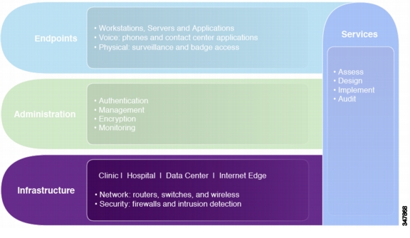
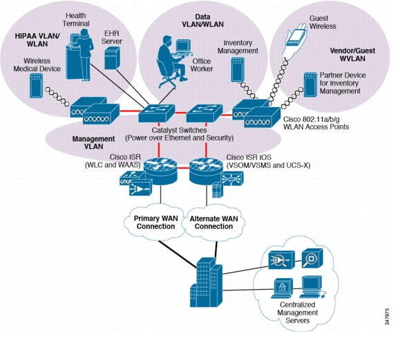
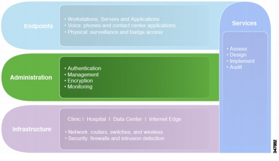
Infrastructure
The infrastructure layer of the solution framework addresses the components such as routers, switches, firewalls, and security components. These are used for reference architectures for a variety of locations such as hospitals or data centers as shown in Figure 4-1.
Figure 4-1 Infrastructure Layer of the Solution Framework
The following sections describe the designs that were implemented from the reference architecture.
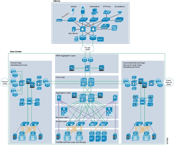
Figure 4-2 shows the enterprise-wide reference architecture.
Figure 4-2 Enterprise-Wide Reference Architecture
Referencing an enterprise-wide architecture as shown in Figure 4-2, the design shown in Figure 4-3 was created in the Cisco lab.
Figure 4-3 Cisco Lab Reference Architecture
Note the following:
•
•
•
The following sections describe this enterprise-wide design in more detail, and demonstrate what was implemented within the lab.
Healthcare Facilities—Clinics and Hospitals
Multiple healthcare facility footprints were implemented that address a variety of business objectives. Each footprint section contains designs that were extracted from the reference architecture. Each design contains the following:
•
•
–
–
–
For component compliance functionality, see Chapter 5, "Component Assessment." For full device configurations, see "Detailed Full Running Configurations."
Note
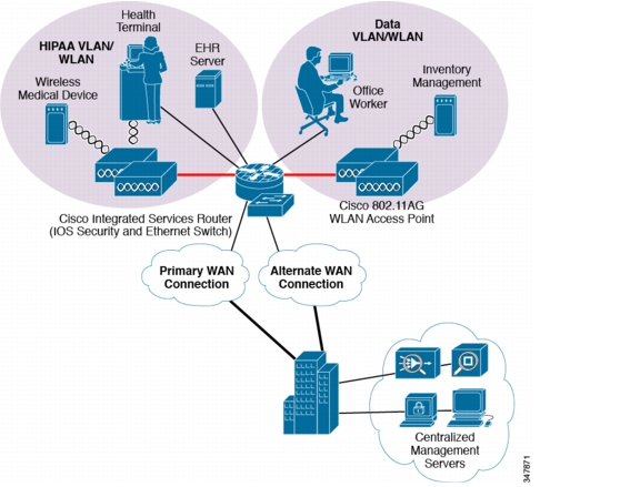
Small Clinic Architecture
Small clinics, such as a single physician or small physician practice, as shown in Figure 4-4, meet the following design requirements:
•
•
•
•
•
•
•
Figure 4-4 Small Clinic Architecture
The small clinic reference architecture is a powerful and modular platform for running multiple parallel and independent healthcare practices, all operating under a common operational and technical infrastructure. The small clinic module dictates simplicity and a compact form factor. This combination appeals to many clinical formats that can include the following:
•
•
•
•
This network architecture is modular and consolidates many services into few infrastructure components. It supports a variety of clinic application models because an integrated Ethernet switch supports high-speed LAN services. Clinics routinely have minimal space for the technology infrastructure. The ability to implement the technological components securely in minimal space is an advantage.
Advantages include the following:
•
•
•
•
Limitations include the following:
•
•
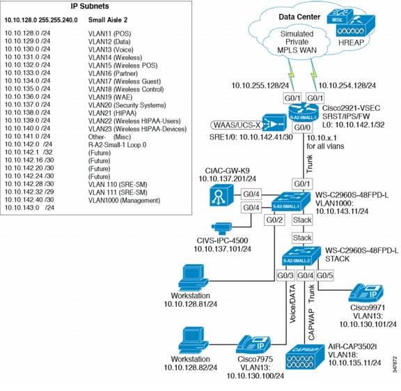
Small Clinic Design
Figure 4-5 shows the small clinic network design.
Figure 4-5 Small Clinic
Components Required
•
•
•
•
•
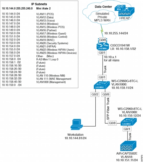
Small Clinic—Mini Design
The mini clinic represents an alternate design for the small architecture, using different components.
Figure 4-6 shows the mini clinic network design.
Figure 4-6 Mini Clinic Network Design
Components Selected
•
•
•
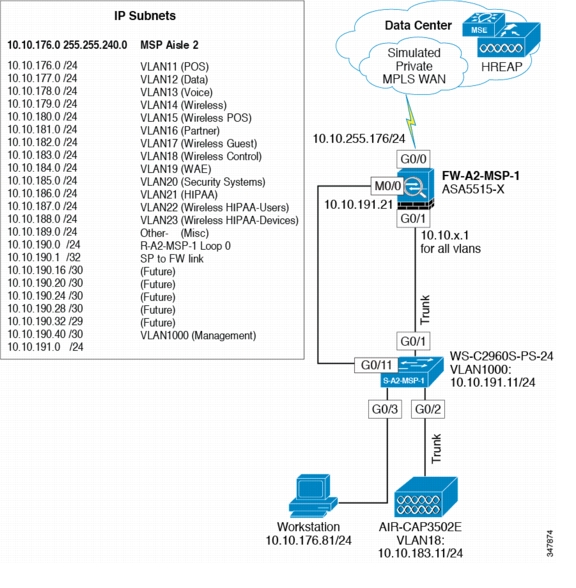
Small Clinic—Managed Service Provider Design
The managed service provider office represents an alternate design for the small clinic architecture. Figure 4-7 shows the managed service provider network design.
Figure 4-7 Managed Service Provider Office Network Design
Components Selected
•
•
•
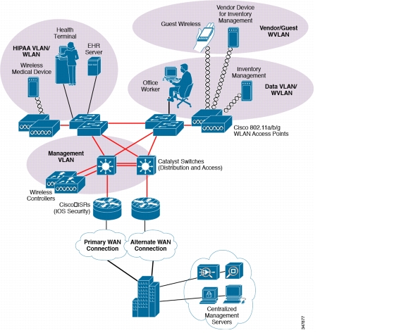
Medium Clinic Architecture
Medium clinics such as a physician practice or multi-practice, shown in Figure 4-8, meet the following design requirements:
•
•
•
•
•
Figure 4-8 Medium Clinic Architecture
The medium clinic architecture provides for flexibility to support a wide range of clinic operations under a common and cost-effective networking model. This model stresses the adaptability of the architecture to multiple functions and data types, all brought under a common control structure so the healthcare security requirements can be controlled either at the clinic or centrally across the larger organization. The medium clinic architecture is optimized for efficient business operation without sacrificing centralized controls and layered security control to best resist breach.
Owing to the flexibility of the architecture, the medium clinic model can be adapted to many configurations of out-patient clinics and today's small hospitals.
The reference architecture is designed for clinical operations that require network resiliency and increased levels of application availability over the small clinic architecture and its single-threaded, simple approach. As more mission-critical applications and services converge onto the IP infrastructure, network uptime and application availability are more important. The dual-router and dual-LAN switch design of the medium clinic supports these requirements. Each of the ISR routers can run Cisco IOS security services and other clinic communication services simultaneously. Each of the Cisco ISR routers is connected to a dedicated WAN connection. Hot-Standby Routing Protocol (HSRP) is used to ensure network resilience in the event that the network connection fails.
The access layer of the network offers enhanced levels of flexibility and more access ports compared to the small clinic. Up to 12 wireless access points can be installed in the clinic, supported by the Cisco Wireless LAN Controller (WLC) as tested and without adding more controllers. The distributed Cisco Catalyst switches can support a combination of larger physical buildings or a larger number of endpoints than the small clinic.
Advantages include the following:
•
•
•
Limitations include the following:
•
•
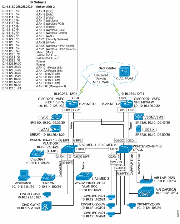
Medium Clinic Design
Figure 4-9 shows the medium clinic design.
Figure 4-9 Medium Clinic Design
Components Selected
•
•
•
•
•
•
•
•
Hospital Architecture
The hospital reference architecture model shown in Figure 4-10 meets the following design requirements:
•
•
•
•
•
•
•
Figure 4-10 Hospital Architecture
The hospital reference architecture uses Cisco campus network architecture recommendations and adapts them to a healthcare environment. Network traffic can be better segmented (logically and physically) to meet business requirements. The distribution layer architecture can greatly improve LAN performance while offering enhanced physical media connections (that is, fiber and copper for connection to remote access layer switches and wireless access points). A larger number of endpoints can be added to the network to meet business requirements. Dual routers and distribution layer media flexibility greatly improve network serviceability because the network is highly available and scales to support the site requirements. Routine maintenance and upgrades can be scheduled and performed more frequently or during normal business hours because of parallel path design.
Advantages include the following:
•
•
•
•
Limitations include the following:
•
•
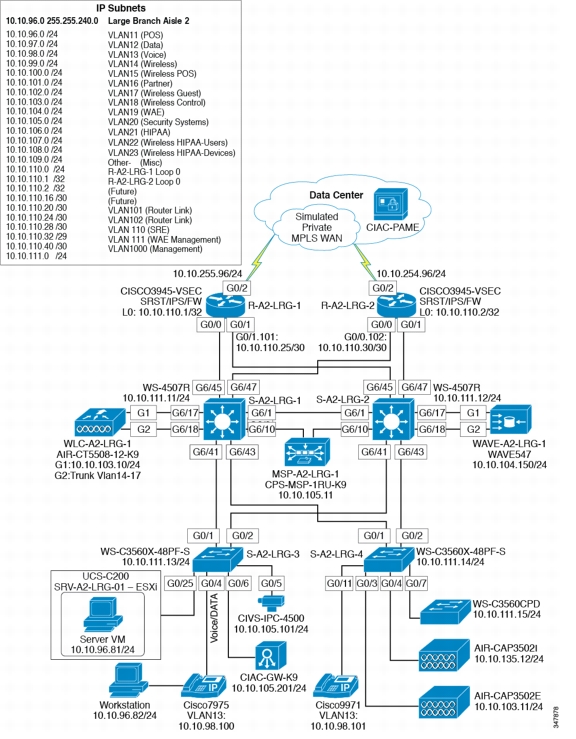
Hospital Design
Figure 4-11 shows the hospital network design.
Figure 4-11 Hospital Network Design
Components Selected
•
•
•
•
•
•
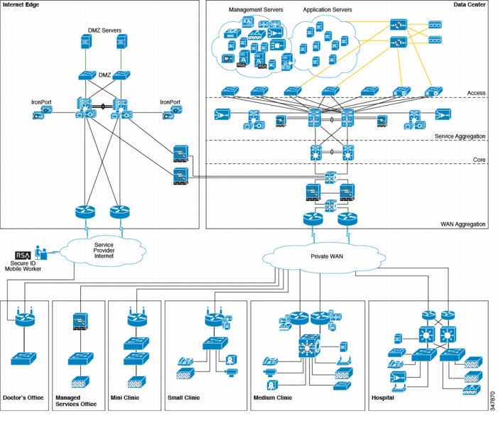
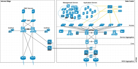
Data Center
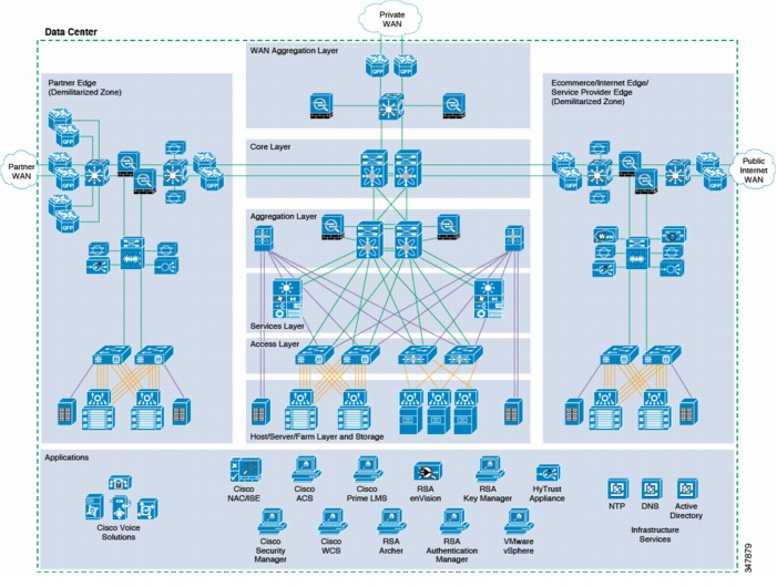
The data center is where centralized data communications occur and are stored (see Figure 4-12). The data center is also the place where management systems are deployed. The data center provides centralized control from an administrative perspective because it is typically where the tools that are used to monitor and enforce compliance are deployed.
Figure 4-12 Data Center Architecture
Design considerations are as follows:
•
•
•
•
•
•
•
•
•
•
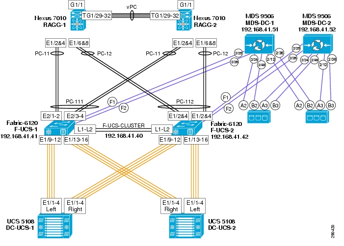
Figure 4-13 shows the data center design.
Figure 4-13 Data Center Design
Data centers can house many types of functions, and the term itself can encompass narrow and broad aspects. For the purposes of this guide, data centers include the following functions:
•
•
•
•
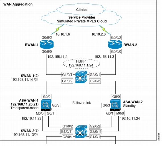
WAN Aggregation Layer
Figure 4-14 shows the WAN aggregation layer design.
Figure 4-14 WAN Aggregation Layer Design
Components Selected
•
•
•
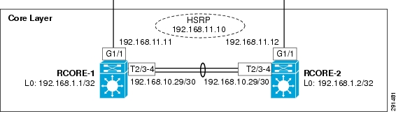
Core Layer Design
Figure 4-15 shows the core layer design.
Figure 4-15 Core Layer Design
Components Selected
•
Note
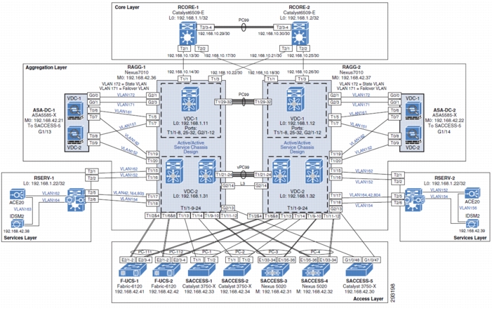
Aggregation Block Design
Figure 4-16 shows the aggregation block design.
Figure 4-16 Aggregation Block Design
Components Selected
•
•
•
–
–
•
•
Vblock Design
Figure 4-17 shows the Vblock design.
Figure 4-17 Vblock Design
Components Selected
•
–
•
•
•
Internet Edge Design
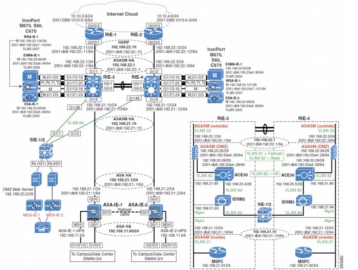
Figure 4-18 shows the Internet edge design.
Figure 4-18 Internet Edge Design
Components Selected
•
•
–
–
–
•
•
•
Administration
The administration layer of the solution framework addresses the components such as authentication, encryption, management, and monitoring, as shown in Figure 4-19.
Figure 4-19 Scope Administration Layer of the Solution Framework
Authentication
Components Selected
•
•
•
•
PHI Encryption
Components Selected
•
•
•
•
Management
Components Selected
•
•
•
•
•
•
•
•
Monitoring
Components Selected
•
•
Endpoints and Applications
The endpoints and applications layer of the solution framework addresses the components such as voice and physical security, as shown in Figure 4-20.
Figure 4-20 Endpoints and Applications Layer of the PHI Solution Framework
Physical
Components Selected
•
•
Voice
Components Selected
•
•
•
Services
The right-hand element that spans endpoint, administration, and infrastructure layers includes services to plan, build, and manage the network to address the HIPAA Security Rule. These can be provided by Cisco, Cisco partners, and Verizon Business. Sample services can include the following:
•
•
•
•
•
•
•
•
Note
Cisco Compliance Solution for HIPAA Security Rule Result Summary
This solution combines components to create an end-to-end solution conforming to the security controls requirements as outlined in the HIPAA Security Rule Safeguards (see Table 4-1). The result is a set of recommended clinic, hospital, data center, and Internet-edge architectures and designs that can simplify the process of developing and maintaining healthcare security controls in support of a risk management program as required by HIPAA.