Table Of Contents
Small Branch—Convenience Design
Small Branch—Managed Service Provider Design
Solution Implementation
Overview
Cisco customers have asked Cisco to provide insight into how Cisco products can be used to address PCI DSS 2.0 requirements. To fully accomplish this goal, Cisco hired an auditor and went through the same process as organizations. To audit Cisco products for the capability to address compliance, they had to be installed and configured within a representative design.
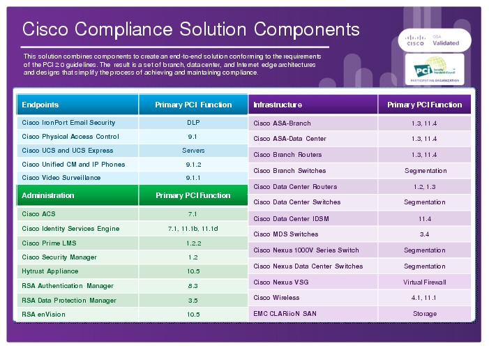
This chapter demonstrates how the Cisco PCI solution was installed and configured to address the specifications of PCI 2.0. Cisco partnered with RSA, HyTrust, EMC, VCE, and Verizon Business to create a comprehensive design that reflected the framework and architectural principles discussed in earlier chapters.
The Cisco PCI solution was validated in the Cisco Lab in San Jose, California. The branches, data center, WAN, and Internet edge network infrastructures were built using Cisco best practice design guides, as represented by the Cisco enterprise architecture (http://www.cisco.com/go/designzone). The individual components were installed and configured to adhere to PCI 2.0 specifications. Verizon Business then conducted an assessment of the design and advised on remediation for specific configurations of individual components. After the remediation was complete, Verizon Business provided a detailed reference architecture report (see Appendix C, "Verizon Business Reference Architecture Report—Cisco PCI Solution.")
Tip
An architecture is a strategic structure for the consistent design, construction, and operation of systems to achieve a desired set of outcomes.
A design is a tactical implementation of an architectural strategy, using specific configurations of products to satisfy business requirements.
Chapter 3, "Solution Architecture," describes the enterprise architecture with regards to compliance. This chapter demonstrates a design or, in other words, a specific implementation of components to achieve these principles. Various designs can result from the solution architecture. The design that was implemented is not intended to represent the only way that Cisco and partner products can be installed to address PCI. It is intended to provide an example showing how and what was used to achieve the principles described in Chapter 3, "Solution Architecture."Although every company has specific considerations that vary from this implementation, these designs and the configurations of the components in "Detailed Full Running Configurations," provide an instructive example of what is needed to secure credit card data. Each component selected was audited for its capabilities, and that assessment is covered in the next chapter.
In each section, the reference architecture is shown with the corresponding design that was implemented and validated within the Cisco PCI laboratories. The full configurations of each individual component are available in "Detailed Full Running Configurations."
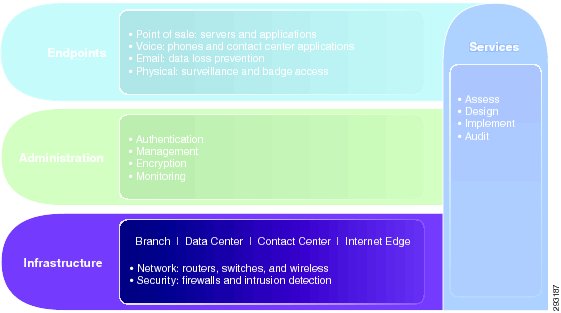
Infrastructure
The infrastructure layer of the solution framework addresses the components such as routers, switches, firewalls, and security components, as shown in Figure 4-1.
Figure 4-1 Infrastructure Layer of the Solution Framework
The following sections describe the designs that were implemented from the reference architecture.
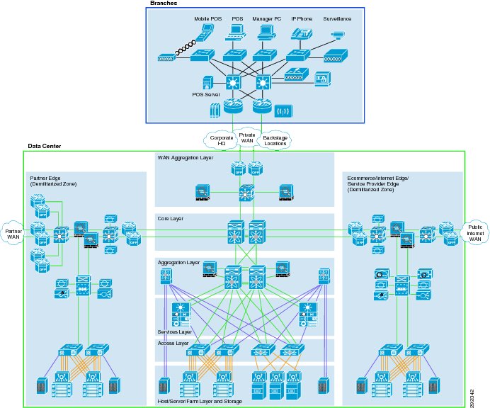
Figure 4-2 shows the enterprise-wide reference architecture.
Figure 4-2 Enterprise-Wide Reference Architecture
Referencing the enterprise-wide architecture shown in Figure 4-2, the design shown in Figure 4-3 was created in the Cisco Lab.
Figure 4-3 Cisco PCI Solution Lab Architecture
Note the following:
•
•
•
The following sections describe this enterprise-wide design in more detail, and demonstrate what was implemented within the lab.
Branches
Multiple branch footprints were implemented that address a variety of business objectives. Each branch footprint section contains designs that were extracted from the reference architecture. Each design contains the following:
•
•
–
–
–
For component compliance functionality, see Chapter 5, "Component Assessment.". For full device configurations, see "Detailed Full Running Configurations."
Note
Small Branch Architecture
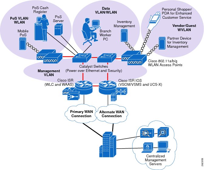
The small branch network scenario, shown in Figure 4-4, meets the following design requirements:
•
•
•
•
•
Figure 4-4 Small Branch Architecture
The small branch reference architecture is a powerful platform for running an enterprise that requires simplicity and a compact form factor. This combination appeals to many formats that can include the following:
•
•
•
•
This network architecture is widely used and consolidates many services into fewer infrastructure components. The small branch also supports a variety of business application models because an integrated Ethernet switch supports high-speed LAN services. In addition, an integrated content engine supports centralized application optimization requirements such as Web Cache Communications Protocol (WCCP)-based caching, pre-positioning of data, local media streaming, and other application velocity services.
Advantages include the following:
•
•
•
•
Limitations include the following:
•
•
Small Branch—Small Design
Figure 4-5 shows the small branch network design.
Figure 4-5 Small Branch Network Design
Components Selected
•
•
•
•
•
Small Branch—Mini Design
The mini branch represents an alternate design for the small branch architecture, using different components.
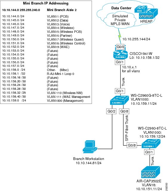
Figure 4-6 shows the mini branch network design.
Figure 4-6 Mini Branch Network Design
Components Selected
•
•
•
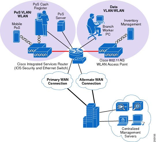
Small Branch—Convenience Design
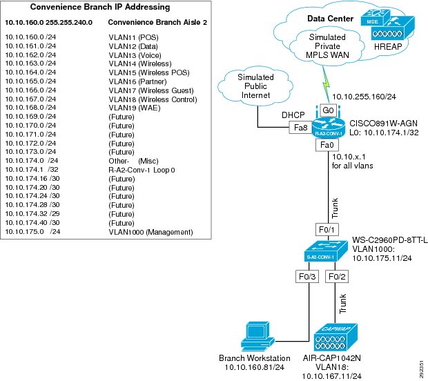
The convenience branch represents an alternate design for the small branch architecture. Figure 4-7 shows the convenience branch network design.
Figure 4-7 Convenience Branch Network Design
Components Selected
•
•
•
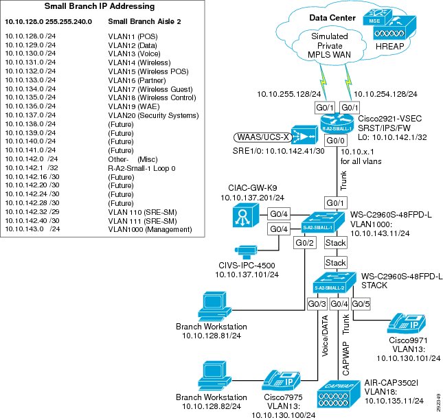
Small Branch—Managed Service Provider Design
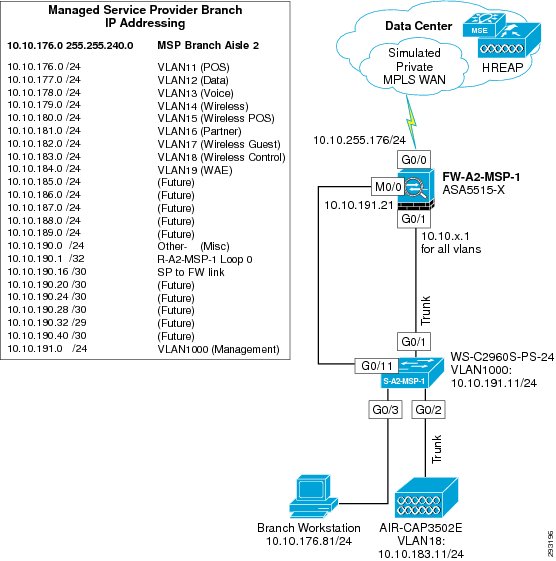
The managed service provider branch represents an alternate design for the small branch architecture. Figure 4-8 shows the managed service provider network design.
Figure 4-8 Managed Service Provider Branch Network Design
Components Selected
•
•
•
Medium Branch Architecture
The medium branch network scenario, shown in Figure 4-9, meets the following design requirements:
•
•
•
•
•
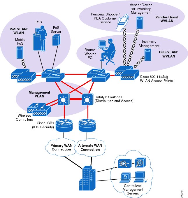
Figure 4-9 Medium Branch Architecture
The medium branch reference architecture is designed for enterprise businesses that require network resilience and increased levels of application availability over the small branch architecture and its single-threaded, simple approach. As more mission-critical applications and services converge onto the IP infrastructure, network uptime and application availability are more important. The dual-router and dual-LAN switch design of the medium branch supports these requirements. Each of the Cisco ISR routers can run Cisco IOS Software security services and other branch communication services simultaneously. Each of the Cisco ISR routers is connected to a dedicated WAN connection. Hot Standby Routing Protocol (HSRP) is used to ensure network resilience in the event that the network connection fails.
The access layer of the network offers enhanced levels of flexibility and more access ports compared to the small branch. Up to 12 wireless access points can be installed in the branch, supported by the Cisco Wireless Control System (WCS) controller as tested and without adding more controllers. The distributed Cisco Catalyst switches can support a combination of larger physical buildings or a larger number of endpoints than the small branch.
Advantages include the following:
•
•
•
Limitations include the following:
•
•
Medium Branch—Design
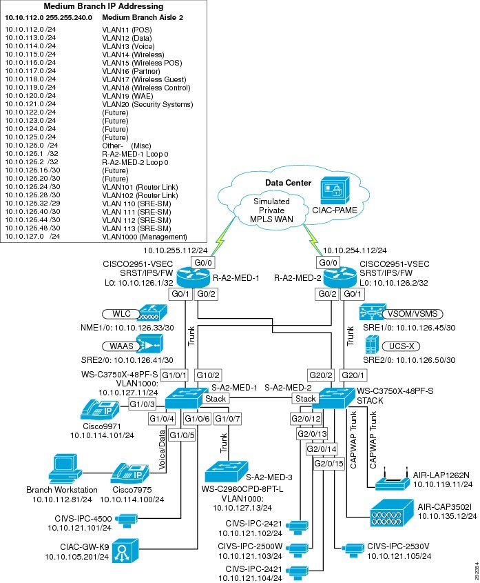
Figure 4-10 shows the medium branch network design.
Figure 4-10 Medium Branch Network Design
Components Selected
•
•
•
•
•
•
•
•
Large Branch Architecture
The large branch network scenario, shown in Figure 4-11, meets the following design requirements:
•
•
•
•
•
Figure 4-11 Large Branch Architecture
The large branch reference architecture takes some of the elements of Cisco campus network architecture recommendations and adapts them to a large branch environment. Network traffic can be better segmented (logically and physically) to meet business requirements. The distribution layer of the large branch architecture can greatly improve LAN performance while offering enhanced physical media connections (that is, fiber and copper for connection to remote access layer switches and wireless access points). A larger number of endpoints can be added to the network to meet business requirements. This type of architecture is widely used by large format organizations globally. Dual routers and distribution layer media flexibility greatly improve network serviceability because the network is highly available and scales to support the large branch requirements. Routine maintenance and upgrades can be scheduled and performed more frequently or during normal business hours because of parallel path design.
Advantages include the following:
•
•
•
•
Limitations include the following:
•
•
Large Branch Design
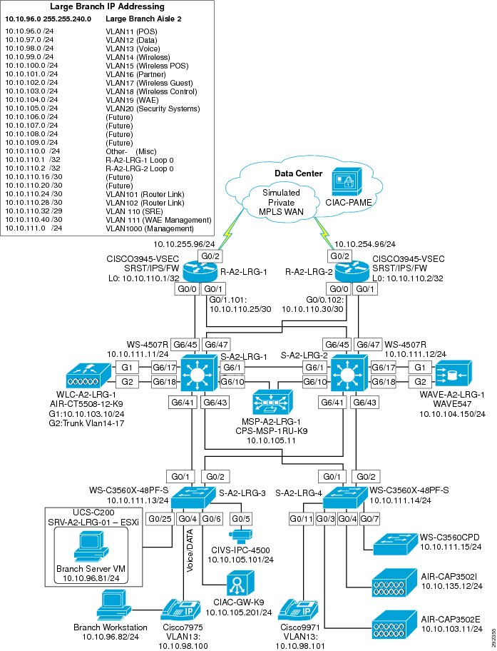
Figure 4-12 shows the large branch network design.
Figure 4-12 Large Branch Network Design
Components Selected
•
•
•
•
•
•
Data Center
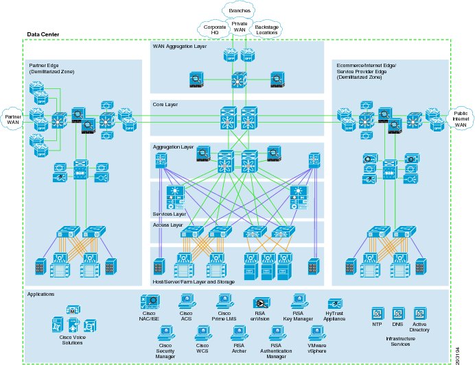
The data center is where centralized data processing, data storage, and data communications take place (see Figure 4-13). The data center is also the place where management systems are deployed. The data center provides centralized control from an administrative perspective because it is typically where the tools that are used to monitor and enforce compliance are deployed.
Figure 4-13 Data Center Architecture
Design considerations are as follows:
•
•
•
•
•
•
•
•
•
•
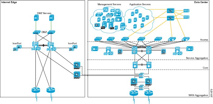
Figure 4-14 shows the data center design.
Figure 4-14 Data Center Design
Data centers can house many types of functions and the term itself can encompass narrow and broad aspects. For the purposes of this guide, data centers include the following functions:
•
•
•
•
WAN Aggregation Layer Design
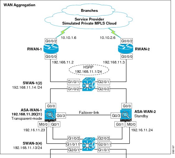
Figure 4-15 shows the WAN aggregation layer design.
Figure 4-15 WAN Aggregation Layer Design
Components Selected
•
•
•
Core Layer Design
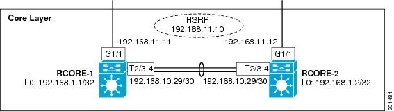
Figure 4-16 shows the core layer design.
Figure 4-16 Core Layer Design
Components Selected
•
Aggregation Block Design
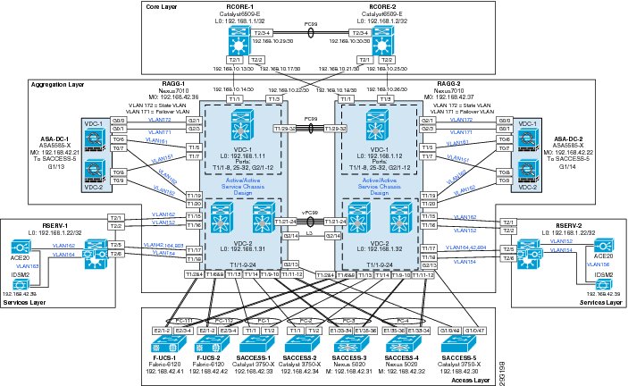
Figure 4-17 shows the aggregation block design.
Figure 4-17 Aggregation Block Design
Components Selected
•
•
•
–
–
•
•
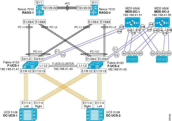
Vblock Design
Figure 4-18 shows the Vblock design.
Figure 4-18 Vblock Design
Components Selected
•
–
•
•
•
Internet Edge Design
Figure 4-19 shows the Internet edge network design.
Figure 4-19 Internet Edge Network Design
Components Selected
•
•
–
–
•
•
•
Addressing and Routing Disclosure
PCI requirement 1.3.8 states that merchants must not disclose private addressing and routing information. An enterprise contains two segments:
•
•
Both may be deployed internally within an enterprise data center or other PIN. The private information must be protected and not propagated out to untrusted parties.
In 2013, it is common for enterprises to deploy an IPv6 Internet presence by using the Server Load Balancing (SLB) to do protocol family translation; that is, when the SLB receives an IPv6 inbound connection from the Internet, the SLB translates this connection on the fly into an IPv4 connection to the real servers.
In this solution, PCI 1.3.8 was met because all the security pieces for IPv4 are also used for IPv6 connections. Moreover, the servers where the information resides have no IPv6 addresses and cannot be reached over IPv6. The attack surface of the servers is strictly the IPv4 attack surface.
Note
A best practice when implementing IPv6 is a phased approach. Figure 4-20 illustrates the scenario described above as the first phase of an IPv6 deployment.
Figure 4-20 IPv6 Phased Approach
Administration
The administration layer of the solution framework addresses the components such as authentication, encryption, management, and monitoring, as shown in Figure 4-21.
Figure 4-21 Administration Layer of the Solution Framework
Authentication
Components Selected
•
•
•
•
Encryption
Components Selected
•
•
•
Management
Components Selected
•
•
•
•
•
•
•
•
Monitoring
Components Selected
•
•
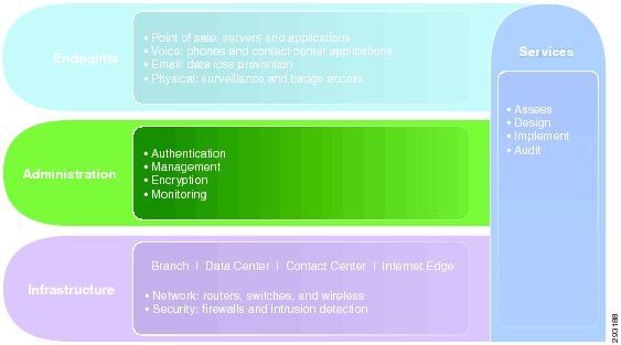
Endpoints
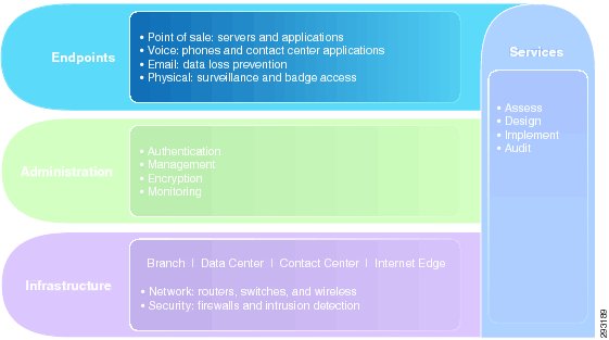
The endpoints layer of the solution framework addresses the components such as voice, e-mail, and physical security, as shown in Figure 4-22.
Figure 4-22 Endpoints Layer of the PCI Solution Framework
Voice
Components Selected
•
•
•
Components Selected
•
•
Physical
Components Selected
•
•
Note
PCI Solution Result Summary