Table Of Contents
Enterprise Architecture and PCI Design Considerations
E-commerce/Internet Edge/Service Provider Edge/Partner Edge
Solution Architecture
The Cisco PCI solution is a set of architectures, strategic principles, and tactical designs that details a holistic approach to addressing the requirements of PCI DSS 2.0. The Cisco enterprise architecture is used as a baseline for demonstrating the range of places that typically exist within an enterprise. This chapter describes the Cisco enterprise architecture in detail, so that when the discussion of specific PCI controls is discussed, the controls can be placed in context with that enterprise-wide view. The solution looks at an enterprise from an end-to-end perspective; from the branch, where someone swipes the credit card, to the back-end of the data center, where the transaction leaves the organization's network to be processed by the acquiring bank.
For more information on the individual components used to build these architectures, see Chapter 4, "Component Assessment."
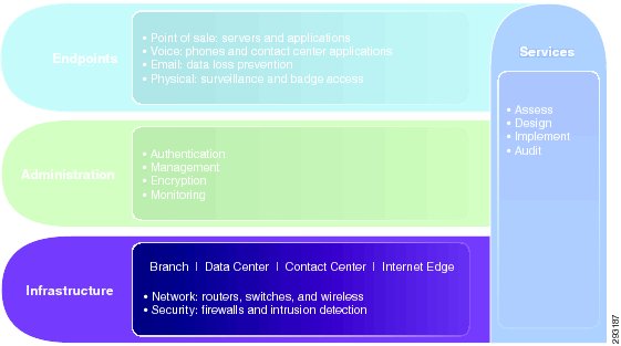
Chapter 2, "PCI and the Solution Framework," describes the elements that make up the solution framework. The solution framework organizes the scope of the cardholder data environment for contextual reference. The bottom layer of the model shows the organization of the enterprise into places such as the branch, data center, and the Internet edge. (See Figure 3-1.)
Figure 3-1 Cisco PCI Solution Framework
Enterprise Architecture and PCI Design Considerations
PCI compliance affects the overall enterprise architecture, depending on the requirements of the business. For example, a new business requirement for direct customer Internet connectivity at the branch level extends the firewall and IDS/IPS perimeter requirements to the branch level, whereas before it might exist only at the headend data center. Without this contextual reference, it is difficult to discuss specific controls.
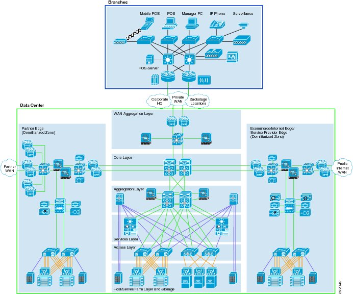
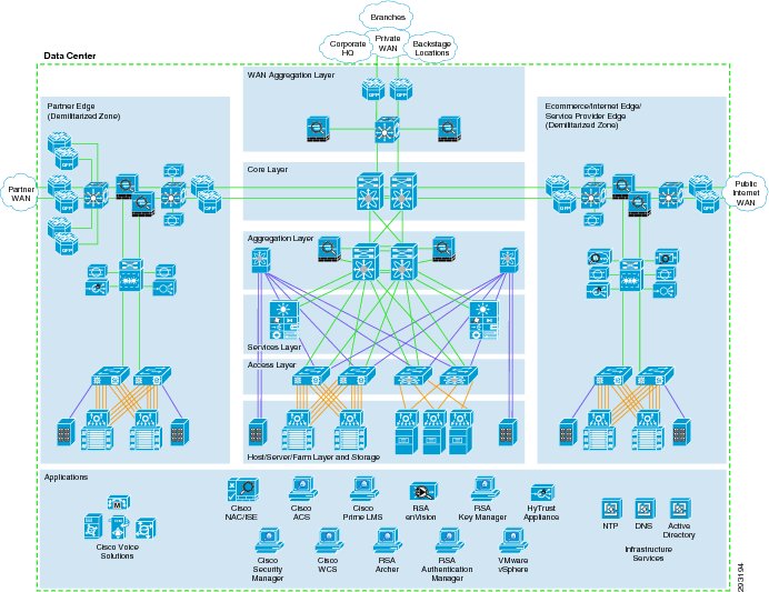
Figure 3-2 shows the enterprise-wide reference architecture and locations that commonly exist in an organization's domain.
Figure 3-2 Enterprise-wide Reference Architecture
Enterprise Network Addressing
Segmentation partitions sensitive data from non-sensitive data. By separating sensitive information from normal information, you are able to treat it differently. Enterprise addressing plans should take this into account by separating compliance data onto its own set of addresses. Whether in the data center or in the branch, by having compliance data use its own addressing plan, you are able to enforce its boundaries with the required controls depending on the contextual risk.
Design Considerations
Within the Branch
Branch addressing should have a separate network for payment involved applications and equipment. This should be separated from normal data, wireless data, wired/wireless guest and other compliance data.
Within the Data Center/Internet Edge
PCI DSS Sub-requirement 1.3.8 states: "Do not disclose private IP addresses and routing information to unauthorized parties." This aligns with the defense-in-depth strategy. By obfuscating internal addressing schemes to the public, especially addresses that could be attacked with payment card information, you reduce your attack surface.
Regardless of the IP version that an enterprise uses (IPv4 or IPv6), methods must be used that eliminate the visibility of the internal addressing scheme. Proxy, NAT, route filtering, and other methods achieve this. Since the World IPv6 Launch of 2012, IPv6 is becoming more commonly deployed within enterprise merchants and service provider offerings. However, not all vendor technology necessarily supports IPv6. so compliance consideration must be given when deploying it.
The following sections describe the major places affected by PCI compliance throughout the enterprise. Each section provides design considerations that are affected by PCI controls in more detail.
The following sections describe the major places affected by PCI compliance throughout the enterprise. Each section provides design considerations that are affected by PCI controls in more detail.
Branch Architecture
The branch is the location where customers swipe their credit cards to purchase goods. Depending on the type of services that are offered at the branch, various levels of security are required. This section discusses those design considerations and relates them to various branch formats.
Design Considerations
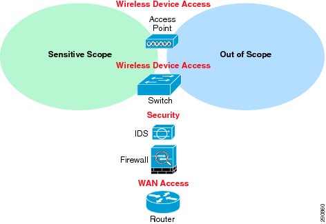
Figure 3-3 shows the fundamental infrastructure components used within a branch location. These components are used in conjunction with each other to segment sensitive data from non-sensitive data. The process of segmenting the network into scopes allows an organization to reduce the amount of branch-level components that need to be audited. Note that devices/endpoints themselves may be cut out of the scope of an audit by putting them onto their own network, but the actual network infrastructure may not necessarily be decreased. For example, a switch can have devices that are both sensitive and non-sensitive attached to it. By putting the non-sensitive devices onto their own VLANs, they can be cut out of the audit by using the VLAN function of the switch. However, the switch itself still remains in scope.
Figure 3-3 Fundamental Branch Infrastructure Components
Each branch component is used for a different function, as follows:
•
The router function can be used for:
–
–
–
•
–
–
–
•
•
–
–
•
–
–
The function of each of these devices can be virtualized and consolidated for simplicity, depending on the space and management requirements of the branch footprint. For example, some smaller branches have power, wiring closet, rack, and cabling restraints that would benefit from virtualized devices that reduce the physical footprint of the branch infrastructure.
Conversely, each of these devices can be increased in number depending on the resiliency and redundancy requirements of the business. For example, if branch connectivity is a business priority, using redundant routers for redundant WAN access might be a requirement to ensure that branch connectivity is maintained.
Regardless of how the branch is designed from a redundancy or scale perspective, the same types/locations of controls are consistent across them.
Many organizations use their data center as their centralized location to connect to public networks such as the Internet. This perimeter is typically secured as a demilitarized zone (DMZ) using firewalls and IDS/IPS. Whenever you introduce any type of untrusted network (wireless, Internet, microwave, satellite, cellular, and so on) into the branch environment, you have effectively created a new external perimeter that must now be secured with a firewall and intrusion detection/prevention system. Table 3-1 defines the types of factors that affect branch controls and requirements.
The fundamental reference branch architecture assumes that an organization may eventually need to scale to these levels of services, but not necessarily immediately. From a branch perspective, the Cisco Integrated Services Router (ISR) performs each of the functions listed in Table 3-1. This allows organizations to grow with their investment by purchasing a router that can scale by different license keys for different services without having to rip and replace. For example, a business can purchase a Cisco ISR for basic WAN connectivity. When the business wants to introduce wireless to the branches, the business can then unlock the firewall/IPS/IDS feature set with a license.
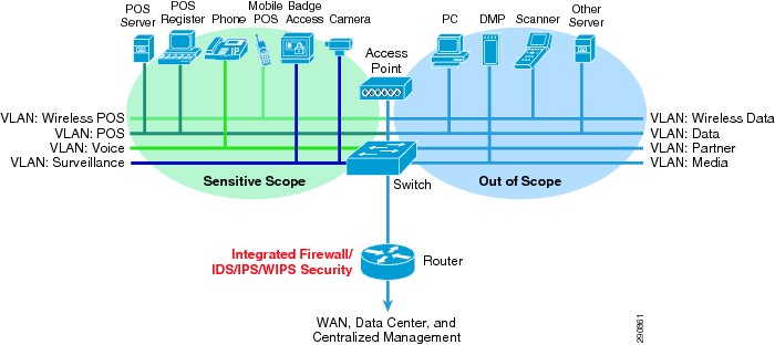
The fundamental branch reference architecture in Figure 3-4 shows the solution framework endpoints/applications within the context of the fundamental branch component's infrastructure.
Figure 3-4 Fundamental Reference Branch Architecture
In-scope devices can include the following:
•
•
•
•
•
•
In general, an additional VLAN for management of infrastructure should be distinctly defined.
The remaining devices at the branch level are considered out-of-scope and do not need to be audited, given that they are on their own network and segmented via firewall/IPS/IDS from the sensitive networks.
The PCI branch model and its controls were applied to the small, medium, and large enterprise footprints. This section provides sample addressing plans used by various branches. Many designs can be extracted by understanding and using the PCI solution model shown above, but the overall functions are essentially the same.
Data Center
The data center is where centralized data processing, data storage, and data communications take place (see Figure 3-5). The data center is also the place where management systems are deployed. The data center provides centralized control from an administrative perspective because it is typically where the tools that are used to monitor and enforce compliance are deployed.
Figure 3-5 Data Center Architecture
Design Considerations
Design considerations are as follows:
•
•
•
•
•
•
•
•
•
Data centers can house many types of functions, and the term itself can encompass narrow and broad aspects. For the purposes of this guide, data centers include the following functions:
•
•
•
•
•
•
•
•
•
•
WAN Aggregation
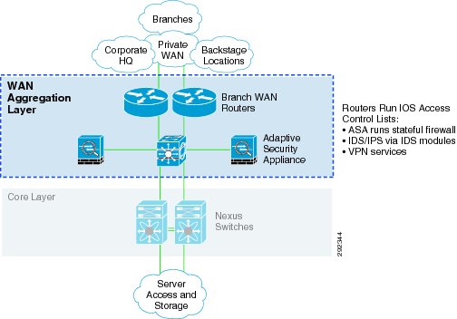
The WAN aggregation layer is a transit network that aggregates the connections from the branches, backstage locations, and corporate offices, as shown in Figure 3-6.
Figure 3-6 WAN Aggregation Layer
Design Considerations
The WAN edge routers should not also be used as the Internet gateways for the data center network. By clearly defining zones of separation of responsibility within the infrastructure, it is easier to maintain.
Two options are possible at this layer for Layer 3 filters at the WAN aggregation layer:
•
•
There are two typical WAN speeds categories for a WAN aggregation network: less than and up to OC3 (155 Mbps), and OC12 (622 Mbps) and above. The choice of these two network speeds determines the platform set to select from Cisco. In addition, this design creates two profiles for each WAN speed. These profiles are designed to provide guidance when designing a WAN edge network, regardless of which enterprise WAN architecture is selected. The profiles for each WAN speed investigate integrated versus dedicated chassis for each functionality component, as highlighted in the previous section. Some customers prefer a highly integrated solution where most, if not all, of the WAN edge functions described in this document reside on a single or very few network devices. Other customers prefer the granularity and scalability of these same functions separated across multiple network devices.
The WAN aggregation architecture is based on the Infrastructure Protection and Security Service Integration Design for the Next Generation WAN Edge v 2.0, which can be found at the following URL: http://www.cisco.com/en/US/docs/solutions/Enterprise/WAN_and_MAN/IPSNGWAN.html
Core Layer
The core layer provides the high-speed packet switching backplane for all flows going throughout of the data center, as shown in Figure 3-7.
Figure 3-7 Core Layer
Design Considerations
The core layer provides connectivity to multiple aggregation layers and provides a resilient Layer 3 routed fabric with no single point of failure. The core layer runs an interior routing protocol, such as Open Shortest Path First (OSPF) or Enhanced Interior Gateway Routing Protocol (EIGRP), and load balances traffic between the core and aggregation layers using the Cisco Express Forwarding-based hashing algorithms.
The core is not a perimeter; no security filtration should be performed at this layer.
The core, services aggregation, and server access tiers of the multi-tier data center architecture were based on the design documented in the Cisco Data Center Infrastructure Design Guide 3.0, which can be found at the following URL: http://www.cisco.com/en/US/docs/solutions/Enterprise/Data_Center/DC_3_0/DC-3_0_IPInfra.html
Aggregation Block
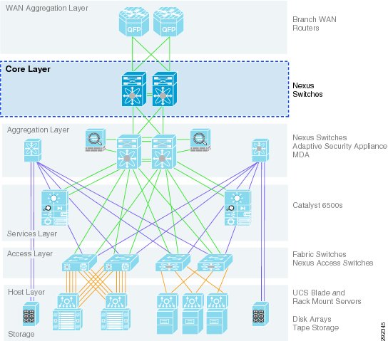
An aggregation block is a combination of the aggregation, services, and access layer systems. It represents a repeatable, implementable template for scaling applications and services within the data center. (See Figure 3-8.)
Figure 3-8 Aggregation Block
Design Considerations
Zones are a best practice to isolate applications and services based on their individual policy requirements. You can securely mix in-scope and out-of-scope applications and services within a single aggregation block.
The layers that comprise the aggregation block are described in more detail below.
For more information, see the following URLs:
•
•
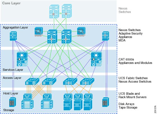
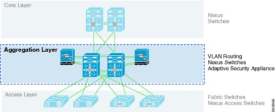
Aggregation Layer
The aggregation layer aggregates the connections from the services layer and the access layer to the centralized core, as shown in Figure 3-9.
Figure 3-9 Aggregation Layer
Design Considerations
The aggregation layer uses Layer 3 filters to segregate and protect the edge of the scope of compliance.
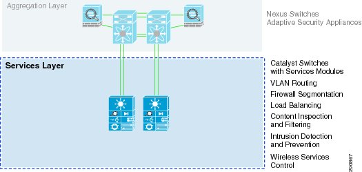
Services Layer
The services layer provides important functions, such as service module integration, Layer 2 domain definitions, spanning tree processing, and default gateway redundancy. (See Figure 3-10.)
Figure 3-10 Services Layer
Design Considerations
Services such as server load balancing and wide-area application services (WAAS) are used at this layer to optimize applications. Optimizing devices used within the scope of PCI are also brought into scope and are susceptible to the same controls as traditional network devices. For more information on understanding these controls, consult the capability assessment logic in Chapter 4, "Component Assessment."
Services such as content switching, SSL offload, intrusion detection, and network analysis are provided by hardware-based service modules or standalone appliances.
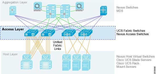
Access Layer
The access layer is where the servers physically attach to the network, as shown in Figure 3-11.
Figure 3-11 Access Layer
In typical data centers, the server components consist of appliances, 1RU servers, blade servers with integral switches, blade servers with pass-through cabling, clustered servers, and mainframes with OSA adapters. The access layer network infrastructure consists of modular switches, fixed configuration 1RU or 2RU switches, and integral blade server switches.
Design Considerations
Switches provide both Layer 2 and Layer 3 topologies, fulfilling the various server broadcast domain or administrative requirements.
The solution management servers connect to the network in this layer. They are centralized, segmented from other business application servers, and protected by firewall services from the service aggregation layer above. Business servers, consisting of POS transaction log servers, database, and data warehouse servers also exist at this layer but are segmented via separate VLANs and firewall policy.
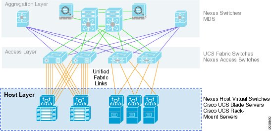
Host/Server Farm Layer
The host/server farm layer is where the centralized administrative applications reside, as shown in Figure 3-12.
Figure 3-12 Host/Server Farm Layer
Design Considerations
Network addressing should be used per business function. This allows the discrete manipulation of data traffic as requirements arise. For example, both POS applications and network management are used within the scope of PCI compliance but should be segregated onto their own subnets.
Virtualization technology can be used within a data center server farm. Individual blades within a blade server chassis can be used to segment sensitive and non-sensitive applications because they run independent hypervisors. Because hypervisors are considered insecure, when mixing sensitive applications with non-sensitive applications (mixed-mode) across the same hypervisor, the non-sensitive applications are now in scope.
For more information, see the PCI Virtualization Guidelines whitepaper at the following URL: https://www.pcisecuritystandards.org/documents/Virtualization_InfoSupp_v2.pdf.
Multiple internal Network Time Protocol (NTP) servers should be deployed for consistent log synchronization in the event of failure. Those internal NTP servers should use more than one external source in the event of an external failure.
Although virtualization can be used for a variety of services, NTP requires a high resolution system clock and accurate response times to clock interrupts that virtual machines cannot provide. For these reasons, it is recommended not to run NTP on virtual machines. Instead, NTP should be run on the base OS of the hypervisor, and the virtual machine should use VMware Tools Clock synchronization to sync with the base host. NTP servers should also not run on virtual machines but on physical devices (for example, on the Cisco Catalyst 6509 Services switches in the services layer of the data center aggregation block). For more details, see the following URL: http://www.vmware.com/files/pdf/Timekeeping-In-VirtualMachines.pdf.
Table 3-2 lists descriptions of applications for administrators.
Storage Layer
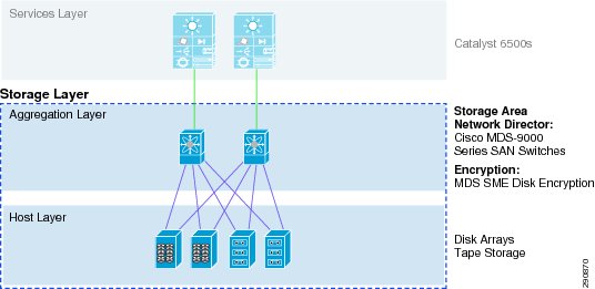
The storage layer is where sensitive data is stored, as shown in Figure 3-13.
Figure 3-13 Storage Layer
Design Considerations
A combination of disk encryption provided by Cisco MDS, Fibre-Channel zoning, and masking were used in the storage implementation of this solution. By deploying zoning within a Fibre Channel fabric, device access is limited to devices within the zone. This allows the user to segregate devices based on access to a particular storage device (disk array). This is a requirement in a data center environment in which multiple file servers in the data center server farm are connected to the same SAN fabric, and access to cardholder data must be restricted to a subset of servers. LUN masking takes zoning beyond the Fibre Channel switchport level, by restricting access to specific LUNs on a given disk array. Only specific devices belonging to the LUN zone are able to access those sections of the disk.
Encryption keys for storage are managed by Cisco Key Manager and RSA Data Protection Manager.
A subtle, yet potentially significant change to key management has been introduced with the PCI 2.0 standard. With past versions of the DSS, annual key rotations were required for encryption keys. DSS 2.0 now requires that keys are rotated at the end of their cryptoperiod, and references the NIST 800-57 Special Publication to determine what an appropriate cryptoperiod is. The NIST 800-57 Special Publication is a 324-page, three-part document. Organizations, and even QSAs, may not have the expertise to fully understand such a document that includes countless encryption scenarios, with cryptoperiods ranging from as short as a day to as long as three years.
In an ideal world, with all parties being expert cryptographers, this risk-based change to the standard would be very appropriate and most welcome. However, given the number of scenarios and criteria for determining an appropriate cryptoperiod, it could suggest that this change is too subjective and may become a point of contention between organization and QSA assessor, as to what is an appropriate cryptoperiod; whereas the former, more prescriptive control, did not allow for flexibility in this area.
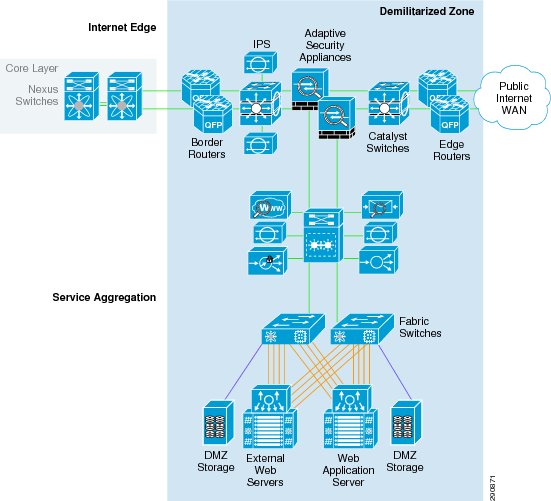
E-commerce/Internet Edge/Service Provider Edge/Partner Edge
The solution uses a collapsed Internet edge and extranet network to support Internet connectivity and business partner connectivity, as shown in Figure 3-14.
Figure 3-14 E-commerce/Internet Edge/Service Provider Edge
Design Considerations
The design does the following:
•
•
•
•
•
This design takes into account best practices from the Data Center Networking: Internet Edge Design Architecture Design Guide (http://www.cisco.com/go/designzone) and customizes these recommendations for the Internet edge and extranet networks of enterprises. The edges connect Internet services to the complete enterprise environment (that is, from headquarters to Internet service providers), and branch office connections that use a Cisco secure VPN to connect to headquarters. The collapsed design provides highly centralized and integrated edge networks, and transports the aggregated traffic through various service modules (Cisco ACE, Cisco ASASM, and Cisco IDSM2) within a pair of Cisco Catalyst 6500 Switch chassis. The Internet edge provides the following security functions:
•
•
•
•
•
•
•