-
Cisco Identity Services Engine User Guide, Release 1.2
-
Preface
-
What's New In This Release
- Introducing Cisco ISE
- Deploying Cisco ISE Nodes
- Setting Up Cisco ISE Management Access
- Managing Users and End-User Portals
- Enabling and Configuring Cisco ISE Services
- Monitoring and Troubleshooting Cisco ISE
-
Reference
-
Administration UI Reference
-
Operations UI Reference
-
Policy UI Reference
-
Sample Code for Sponsor and Guest Portal Customizations
-
Network Access Flows
-
Switch and Wireless LAN Controller Configuration Required to Support Cisco ISE Functions
-
Troubleshooting Cisco ISE
-
Supported Management Information Bases in Cisco ISE
-
-
 Feedback
Table Of Contents
Configuring Cisco Security Group Access Policies
Security Group Access Architecture
Configure SGA Settings on the Switches
Configuring Security Group Access Settings
Configuring Security Group Access AAA Servers
Configure Security Group Access Control Lists
Adding Security Group Access Control Lists
Map Security Groups to Devices
Adding Security Group Mappings
Configuring SGA Policy by Assigning SGTs to Devices
Assigning Security Groups to Users and Endpoints
Configure Egress Policy Table Cells
Adding the Mapping of Egress Policy Cells
Configuring SGT from Egress Policy
Configuring SGACL from Egress Policy
Running Top N RBACL Drops by User
Generating an SGA PAC from the Settings Screen
Generating an SGA PAC from the Network Devices Screen
Generating an SGA PAC from the Network Devices List Screen
Configuring Cisco Security Group Access Policies
This chapter describes how to configure a Cisco Identity Services Engine (Cisco ISE) node as an authentication server, using Security Group Access (SGA) policies. This requires a Cisco SGA solution-enabled network.
This chapter contains the following topics:
•
Security Group Access Architecture
•
Security Group Access Architecture
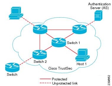
The Cisco Security Group Access (SGA) solution establishes clouds of trusted network devices to build secure networks. Each device in the Cisco SGA cloud is authenticated by its neighbors (peers). Communication between the devices in the SGA cloud is secured with a combination of encryption, message integrity checks, and data-path replay protection mechanisms. The SGA solution uses the device and user identity information that it obtains during authentication to classify, or color, the packets as they enter the network. This packet classification is maintained by tagging packets when they enter the SGA network so that they can be properly identified for the purpose of applying security and other policy criteria along the data path. The tag, also called the security group tag (SGT), allows Cisco ISE to enforce access control policies by enabling the endpoint device to act upon the SGT to filter traffic.
You need an Advanced License Package for Cisco ISE to enable SGA services.
Figure 24-1 shows an example of an SGA network cloud.
Figure 24-1 SGA Architecture
Related Topics
•
SGA Features
The key features of the SGA solution include:
•
•
–
–
–
•
•
•
•
•
–
–
–
•
•
•
SGA Terminology
Table 24-1 lists some of the common terms that are used in the SGA solution and their meaning in an SGA environment.
Supported Switches for SGA
To set up a Cisco ISE network that is enabled with the Cisco SGA solution, you need switches that support the SGA solution and other components. Table 24-2 lists the supported Cisco switch platforms.
Components Required for SGA
Apart from the switches listed in Table 24-2, you need other components for identity-based user access control using the IEEE 802.1X protocol. These include Microsoft Windows 2003 or 2008 Server running Microsoft Active Directory, certificate authority (CA) server, Domain Name System (DNS) server, and Dynamic Host Configuration Protocol (DHCP) server. An end host running the Microsoft Windows operating system can also be a part of this environment. Table 24-3 lists other components that may be required for your Cisco SGA environment.
To enable Cisco ISE to interoperate with SGA deployments, you must configure SGA switch ports on your switches.
Related Topics
"Enable Cisco Security Group Access Switch Ports" section
Enable SGA Solution
This section describes the tasks that you must perform to enable the SGA solution in your Cisco ISE network.
This section contains the following:
•
•
•
•
•
•
Configure SGA Settings on the Switches
To enable Cisco ISE to interoperate with SGA deployments, you must configure SGA switch ports on your switches. See "Enable Cisco Security Group Access Switch Ports" section for more information.
In addition to configuring SGA settings on Cisco ISE, you must also configure some settings on the SGA devices. These configurations vary for the Catalyst and Nexus switches and are described in the Catalyst and Nexus switch configuration guides that are available at the following URLs:
•
•
•
Configuring SGA Devices
For Cisco ISE to process requests from SGA-enabled devices, you must define these SGA-enabled devices in Cisco ISE.
Before You Begin
To perform the following task, you must be a Super Admin or System Admin.
Step 1
Step 2
Step 3
What To Do Next
•
Related Topics
•
•
•
Configuring Security Group Access Settings
For Cisco ISE to function as an SGA server and provide SGA services, you must define some global SGA settings.
Before You Begin
•
You must change the Authority Identity Info Description to your Cisco ISE server name. This description is a user-friendly string that describes the Cisco ISE server that sends credentials to an endpoint client. The client in a Cisco SGA architecture can be either the endpoint running EAP-FAST as its EAP method for IEEE 802.1X authentication or the supplicant network device performing NDAC. The client can discover this string in the protected access credentials (PAC) type-length-value (TLV) information. The default value is Cisco Identity Services Engine. You should change the value so that the Cisco ISE PAC information can be uniquely identified on network devices upon NDAC authentication.
•
Step 1
Step 2
Step 3
What To Do Next
•
Related Topics
•
•
•
Configuring Security Group Access AAA Servers
You can configure a list of Cisco ISE servers in your deployment in the AAA server list to allow SGA devices to be authenticated against any of these servers. When you add Cisco ISE servers to this list, all these server details are downloaded to the SGA device. When an SGA device tries to authenticate, it chooses any Cisco ISE server from this list and, if the first server is down or busy, the SGA device can authenticate itself against any of the other servers from this list. By default, the primary Cisco ISE server is an SGA AAA server. We recommend that you configure additional Cisco ISE servers in this AAA server list so that if one server is busy, another server from this list can handle the SGA request.
This page lists the Cisco ISE servers in your deployment that you have configured as your SGA AAA servers.
You can click the Push button to initiate an environment CoA notification after you configure multiple SGA AAA servers. This environment CoA notification goes to all SGA network devices and provides an update of all SGA AAA servers that were changed.
Before You Begin
To perform the following task, you must be a Super Admin or System Admin.
Step 1
Step 2
Step 3
•
•
•
•
Step 4
What To Do Next
Related Topics
Cisco ISE Admin Groups, Access Levels, Permissions, and Restrictions
Configure Security Groups
A security Group (SG) or Security Group Tag (SGT) is an element that is used in SGA policy configuration. SGTs are attached to packets when they move within a trusted network. These packets are tagged when they enter a trusted network (ingress) and untagged when they leave the trusted network (egress).
SGTs are automatically generated in a sequential manner, but you have the option to reserve a range of SGTs for IP to SGT mapping. Cisco ISE skips the reserved numbers while generating SGTs.
If you have deleted a particular security group, the SGT assigned to this security group does not get reused until all the succeeding SGTs are deleted.
For example, if you have SGTs 2, 3, and 4 defined and you delete SGT 2, the next SGT that is generated would be SGT 5. If you want SGT 2 to be generated next, you must delete SGTs 3 and 4.
SGA service uses these SGTs to enforce the SGA policy at egress.
You can configure security groups from the following pages in the Admin portal:
•
•
•
You can click the Push button to initiate an environment CoA notification after updating multiple SGTs. This environment CoA notification goes to all SGA network devices and provides an update of all SGTs that were changed.
Related Topics
•
Adding Security Groups
Each security group in your SGA solution should be assigned a unique SGT. Even though Cisco ISE supports 65,535 SGTs, having fewer number of SGTs would enable you to deploy and manage the SGA solution easily. We recommend a maximum of 64000 SGTs.
Before You Begin
To perform the following task, you must be a Super Admin or System Admin.
Step 1
Step 2
Step 3
Step 4
What To Do Next
•
•
Related Topics
Cisco ISE Admin Groups, Access Levels, Permissions, and Restrictions
Configure Security Group Access Control Lists
Security group access control lists (SGACLs) are permissions that will be assigned after the SGA policy evaluation. SGACLs restrict the operations that a user can perform based on the role of the user instead of the IP address or subnet mask alone. You can configure SGACLs from the Admin portal.
You can click the Push button to initiate an environment CoA notification after updating multiple SGACLs. This environment CoA notification goes to all SGA network devices and provides an update of all SGACLs that were changed.
Related Topics
•
•
Adding Security Group Access Control Lists
Before You Begin
To perform the following task, you must be a Super Admin or System Admin.
Step 1
Step 2
•
•
•
–
–
–
•
permit icmp
deny all
Step 3
Access Control List Entries for Nexus 7000 Series
The Nexus 7000 Series with Cisco Nexus operating system 4.2 supports the following access control list entries:
deny all
deny icmp
deny igmp
deny ip
deny tcp [{dest | src} {{eq | gt | lt | neq} port-number | range port-number1 port-number2}]
deny udp[{dest | src} {{eq | gt | lt | neq} port-number | range port-number1 port-number2}]
permit all
permit icmp
permit igmp
permit ip
permit tcp [{dest | src} {{eq | gt | lt | neq} port-number | range port-number1 port-number2}]
permit udp[{dest | src} {{eq | gt | lt | neq} port-number | range port-number1 port-number2}]
When you change SGACL ACE, SGACL name, or IP version of an SGACL, all the accumulative changes can be pushed to the SGA network devices by clicking the Push button.
What To Do Next
Configuring SGA Policy by Assigning SGTs to Devices
Related Topics
•
Map Security Groups to Devices
Cisco ISE allows you to assign an SGT to an SGA device if you know the device hostname or IP address. When a device with the specific hostname or IP address joins the network, Cisco ISE will assign the SGT before authenticating it. You can create this mapping from the Security Group Mappings page. Before you perform this action, ensure that you have reserved a range of SGTs. You can map the security groups to devices from the Admin portal.
Related Topics
•
•
Adding Security Group Mappings
You can add security group mappings from the Admin portal.
Before You Begin
To perform the following task, you must be a Super Admin or System Admin.
Step 1
Step 2
Step 3
Step 4
Step 5
Step 6
Step 7
Related Topics
Cisco ISE Admin Groups, Access Levels, Permissions, and Restrictions
Configuring SGA Policy by Assigning SGTs to Devices
You can configure the SGA policy by assigning SGTs to devices. You can assign security groups to devices by using the SGA device ID.
Before You Begin
•
•
Step 1
Step 2
Step 3
Step 4
Step 5
Step 6
Step 7
icon. You can also duplicate an existing condition, but ensure that you change the policy name.
The first rule that evaluates to true determines the result of the evaluation. If none of the rules match, the default rule will be applied; you can edit the default rule to specify the SGT that must be applied to the device if none of the rules match.
Step 8
If an SGA device tries to authenticate after you have configured the network device policy, the device will get its SGT and the SGT of its peers and will be able to download all the relevant details.
Related Topics
Cisco ISE Admin Groups, Access Levels, Permissions, and Restrictions
Assigning Security Groups to Users and Endpoints
Cisco ISE allows you to assign a security group as the result of an authorization policy evaluation. Using this option, you can assign a security group to users and end points.
Before You Begin
•
•
Step 1
Step 2
Step 3
If the conditions specified in this authorization policy is true for a user or endpoint, then this security group will be assigned to that user or endpoint and all data packets that are sent by this user or endpoint will be tagged with this particular SGT.
Related Topics
•
•
Egress Policy
The egress table lists the source and destination SGTs, both reserved and unreserved. This page also allows you to filter the egress table to view specific policies and also to save custom views. When the source SGT tries to reach the destination SGT, the SGA-capable device enforces the SGACLs based on the SGA policy as defined in the Egress Policy. Cisco ISE creates and provisions the policy.
After you create the SGTs and SGACLs, which are the basic building blocks required to create an SGA policy, you can establish a relationship between them by assigning SGACLs to source and destination SGTs.
Each combination of a source SGT to a destination SGT is a cell in the egress policy.
This section contains the following:
•
•
Related Topics
•
View the Egress Policy
You can view the Egress Policy in the Policy > Security Group Access > Egress Policy page.
You can view the Egress policy in three different ways:
Source Tree
The Source Tree view lists a compact and organized view of source SGTs in a collapsed state. You can expand any source SGT to see the internal table that lists all information related to that selected source SGT. This view displays only the source SGTs that are mapped to destination SGTs. If you expand a specific source SGT, it lists all destination SGTs that are mapped to this source SGT and their configurations in a table.
You will see three dots (...) next to some fields. This signifies that there is more information contained in the cell. You can position the cursor over the three dots to view the rest of the information in a quick view popup. When you position the cursor over an SGT name or an SGACL name, a quick view popup opens to display the content of that particular SGT or SGACL.
Destination Tree
The Destination Tree view lists a compact and organized view of destination SGTs in a collapsed state. You can expand any destination SGTs to see the internal table that lists all information related to that selected destination SGT. This view displays only the destination SGTs that are mapped to source SGTs. If you expand a specific destination SGT, it lists all source SGTs that are mapped to this destination SGT and their configurations in a table.
You will see three dots (...) next to some fields. This signifies that there is more information contained in the cell. You can position the cursor over the three dots to view the rest of the information in a quick view popup. When you position the cursor over an SGT name or an SGACL name, a quick view popup opens to display the content of that particular SGT or SGACL.
Matrix View
The Matrix View of the Egress policy looks like a spreadsheet. It contains two axis:
•
•
The mapping of a source SGT to a destination SGT is represented as a cell. If a cell contains data, then it represents that there is a mapping between the corresponding source SGT and the destination SGT. There are two types of cells in the matrix view:
•
•
The Egress Policy cell displays the source SGT, the destination SGT, and the Final Catch All Rule as a single list under SGACLs, separated by commas. The Final Catch All Rule is not displayed if it is set to None. An empty cell in a matrix represents an unmapped cell.
In the Egress Policy matrix view, you can scroll across the matrix to view the required set of cells. The browser does not load the entire matrix data at once. The browser requests the server for the data that falls in the area you are scrolling in. This prevents memory overflow and performance issues.
Related Topics
Matrix Operations
The Matrix view in Cisco ISE looks similar to a spreadsheet. It has source SGT as a row title and destination SGT as a column title. A cell is a crossing of source and destination SGTs. The cell in the matrix view contains the configuration information of source and destination pair to SGACLs. The Matrix view does not display all the fields in order to save the cell area.
Navigating through the Matrix
You can navigate through the matrix either by dragging the matrix content area with the cursor or by using horizontal and vertical scroll bars. You can click and hold on a cell to drag it along with the entire matrix content in any direction. The source and destination bar moves along with the cells. The matrix view highlights the cell and the corresponding row (Source SGT) and column (Destination SGT) when a cell is selected. The coordinates (Source SGT and Destination SGT) of the selected cell are displayed below the matrix content area.
Selecting a Cell in the Matrix
To select a cell in the matrix view, click on it. The selected cell is displayed in different color, and the source and destination SGTs are highlighted. You can deselect a cell either by clicking it again or by selecting another cell. Multiple cell selection is not allowed in the matrix view. Double-click the cell to edit the cell configuration.
Configure Egress Policy Table Cells
Cisco ISE allows you to configure cells using various options that are available in the tool bar. Cisco ISE does not allow a cell configuration if the selected source and destination SGTs are identical to a mapped cell.
This section contains:
•
•
Adding the Mapping of Egress Policy Cells
You can add the mapping cell for Egress Policy from the Policy page.
Step 1
Step 2
Step 3
•
•
Step 4
Step 5
•
•
•
•
Step 6
Configuring SGT from Egress Policy
You can create Security Groups directly from the Egress Policy page.
Step 1
Step 2
Step 3
Related Topics
Configuring SGACL from Egress Policy
You can create Security Group ACLs directly from the Egress Policy page.
Step 1
Step 2
Step 3
Related Topics
Configure Security Group Access Control Lists
Push Button
The Push option in the egress policy initiates a CoA notification that calls the SGA devices to immediately request for updates from Cisco ISE regarding the configuration changes in the egress policy.
Related Topics
Monitor Mode
The Monitor All option in the egress policy allows you to change the entire egress policy configuration status to monitor mode with a single click. Check the Monitor All check box in the egress policy page to change the egress policy configuration status of all the cells to monitor mode. When you check the Monitor All check box, the following changes take place in the configuration status:
•
•
•
Uncheck the Monitor All check box to restore the original configuration status. It does not change the actual status of the cell in the database. When you deselect Monitor All, each cell in the egress policy regains its original configuration status.
Features of Monitor Mode
The monitoring functionality of the monitor mode helps you to:
•
•
•
•
•
Related Topics
•
Running Top N RBACL Drops by User
You can run Top N RBACL Drops by User report as follows:
Step 1
Step 2
Step 3
•
•
•
•
Step 4
Step 5
Step 6
The Unknown Security Group
The Unknown security group is a pre-configured security group that cannot be modified and represents the ox000 SGT.
The Cisco Security Group network devices request for cells that refer to the unknown SGT when they do not have a SGT of either source or destination. If only the source is unknown, the request applies to the <unknown, Destination SGT> cell. If only the destination is unknown, the request applies to the <source SGT, unknown> cell. If both the source and destination are unknown, the request applies to the <Unknown, Unknown> cell.
Default Policy
Default Policy refers to the <ANY,ANY> cell. Any source SGT is mapped to any destination SGT. Here, the ANY SGT cannot be modified and it is not listed in any source or destination SGTs. The ANY SGT can only be paired with ANY SGT. It cannot be paired with any other SGTs. A SGA network device attaches the default policy to the end of the specific cell policy.
•
•
According to Cisco ISE, the cell policy and the default policy are two separate sets of SGACLs that the devices get in response to two separate policy queries.
Configuration of the default policy is different from other cells:
•
•
•
OOB SGA PAC
All SGA network devices possess an SGA PAC as part of the EAP-FAST protocol. This is also utilized by the secure RADIUS protocol where the RADIUS shared secret is derived from parameters carried by the PAC. One of these parameters, Initiator-ID, holds the SGA network device identity, namely the Device ID.
If a device is identified using SGA PAC and there is no match between the Device ID, as configured for that device on Cisco ISE, and the Initiator-ID on the PAC, the authentication fails.
Some SGA devices (for example, Cisco firewall ASA) do not support the EAP-FAST protocol. Therefore, Cisco ISE cannot provision these devices with SGA PAC over EAP-FAST. Instead, the SGA PAC is generated on Cisco ISE and manually copied to the device; hence this is called as the Out of Band (OOB) SGA PAC generation.
When you generate a PAC from Cisco ISE, a PAC file encrypted with the Encryption Key is generated.
This section describes the following:
SGA PAC Provisioning
This section describes the following:
•
•
•
Generating an SGA PAC from the Settings Screen
You can generate an SGA PAC from the Settings screen.
Step 1
Step 2
Step 3
Step 4
Related Topics
Generating the PAC for EAP-FAST
Generating an SGA PAC from the Network Devices Screen
You can generate an SGA PAC from the Network Devices screen.
Step 1
Step 2
Step 3
Step 4
Step 5
Step 6
•
•
The Encryption Key is used to encrypt the PAC in the file that is generated. This key is also used to decrypt the PAC file on the devices. Therefore, it is recommended that the administrator saves the Encryption Key for later use.
The Identity field specifies the Device ID of an SGA network device and is given an initiator ID by the EAP-FAST protocol. If the Identity string entered here does not match that Device ID, authentication will fail.
The expiration date is calculated based on the PAC Time to Live.
Step 7
Generating an SGA PAC from the Network Devices List Screen
You can generate an SGA PAC from the Network Devices list screen.
Step 1
Step 2
Step 3
Step 4
Step 5
Related Topics
Generating an SGA PAC from the Network Devices Screen
Monitoring SGA PAC
You can view SGA PAC provisioning data in the form of a PAC Provisioning Report.
Step 1
Step 2
Step 3
Step 4
Related Topics
SGA CoA
Cisco ISE supports SGA Change of Authorization (CoA) which allows Cisco ISE to notify SGA devices about Security Group changes, so that the devices can reply with requests to get the relevant data.
A CoA notification can trigger a SGA network device to send either an Environment CoA or a Per Policy CoA.
This section contains:
•
CoA Supported Network Devices
Cisco ISE sends CoA notifications to the following network devices:
•
•
•
When Cisco ISE is deployed in a distributed environment where there are several secondaries that interoperate with different sets of devices, CoA requests are sent from Cisco ISE primary node to all the network devices. Therefore, SGA network devices need to be configured with the Cisco ISE primary node as the CoA client.
The devices return CoA NAK or ACK back to the Cisco ISE primary node. However, the SGA session that follows an SGA CoA is handled by the related Cisco ISE secondary node.
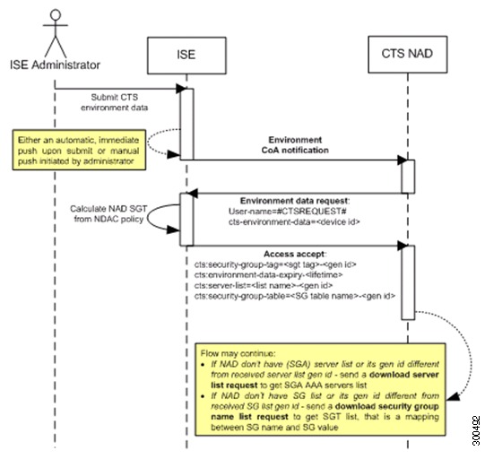
Environment CoA
Figure 24-2 depicts the Environment CoA notification flow.
Figure 24-2 Environment CoA Notification Flow
1.
2.
3.
a.
b.
c.
4.
5.
Initiate Environment CoA
An Environment CoA can be triggered for:
•
•
•
•
Triggering Environment CoA for Network Devices
To trigger an Environment CoA for the Network devices, complete the following steps:
Step 1
Step 2
Step 3
Changing the environment TTL is notified only to the specific SGA network device where the change took place.
Because only a single device is impacted, an environmental CoA notification is sent immediately upon submission. The result is a device update of its environment TTL.
Triggering Environment CoA for Security Groups
To trigger an Environment CoA for the security groups, complete the following steps.
Step 1
Step 2
Step 3
Triggering Environment CoA for SGA AAA Servers
To trigger an Environment CoA for the SGA AAA servers, complete the following steps.
Step 1
Step 2
Step 3
Triggering Environment CoA for NDAC Policy
To trigger an Environment CoA for the NDAC Policies, complete the following steps.
In the NDAC policy page you can create, delete, or update rules of the NDAC policy. These environment changes are notified to all network devices.
You can initiate an environment CoA notification by clicking the Push button in the NDAC policy page. This environment CoA notification goes to all SGA network devices and provides an update of network device own SGT, as described in the "Environment CoA" section.
Per Policy CoA
There are three types of Per Policy CoA notification:
•
•
•
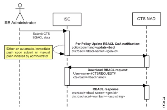
Update RBACL Named List CoA
Figure 24-3 depicts the Update RBACL Named List CoA flow.
Figure 24-3 Update RBACL Named List CoA Notification Flow
1.
2.
a.
b.
3.
Initiating an Update RBACL Named List CoA
To trigger an Update RBACL Named List CoA, complete the following steps:
Step 1
Step 2
Step 3
After you submit a SGACL, it promotes the generation ID of the SGACL.
Step 4
Changing the name or the IP version of an SGACL does not change its generation ID; hence it does not require sending an update RBACL named list CoA notification.
However, changing the name or IP version of an SGACL that is in use in the egress policy indicates a change in the cell that contains that SGACL, and this changes the generation ID of the destination SGT of that cell. See Initiating Update SGT matrix CoA from Egress Policy that deals with changes in the egress policy.
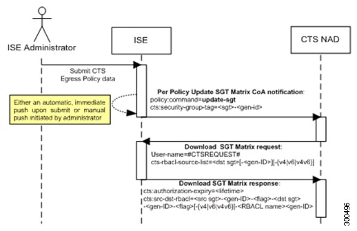
Update SGT Matrix CoA
Figure 24-4 depicts the Update SGT Matrix CoA flow.
Figure 24-4 Update SGT Matrix CoA flow
1.
2.
a.
b.
3.
Initiating Update SGT matrix CoA from Egress Policy
Step 1
Step 2
Step 3
Step 4
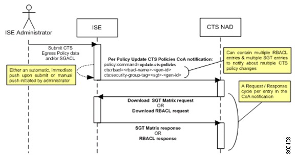
Policies Update CoA
Figure 24-5 depicts the Policies Update CoA flow.
Figure 24-5 Policies Update CoA flow
1.
2.
3.
SGA CoA Summary
Table 24-4 summarizes the various scenarios that may require initiating an SGA CoA, the type of CoA used in each scenario, and the related UI pages.
Monitor SGA CoA
SGA CoA notifications can be viewed as alarms, logs, and reports.
This section describes how to view the following:
SGA CoA Alarms
When CoA returns CoA-NAK, an alarm is generated.
To view SGA CoA alarms, go to Operations > Alarms > Rules.
You can also view the SGA CoA alarms under Live Logs. To view live logs, go to Operations > Alarms > Inbox .
Running SGA CoA Report
You can run the SGA CoA Report as follows:
Step 1
Step 2
You can use the Run button to run the report for a specific period, or use the Query and Run option. The Query and Run option allows you to query the output by using various parameters.