Feedback Feedback
|
Table Of Contents
Attach Inner Rails to the Chassis
Attach the Outer Slide Rail to Round and Square Hole Racks
Attach the Outer Slide Rail to Threaded Hole Racks
Obtaining Documentation and Submitting a Service Request
Slide Rail Installation Instructions
For Cisco C170, M170, and S170 Appliances
and
Cisco 5512-X, 5515-X, 5525-X, 5545-X, 5555-X Adaptive Security Appliances
and
Cisco IPS 4345 and 4360
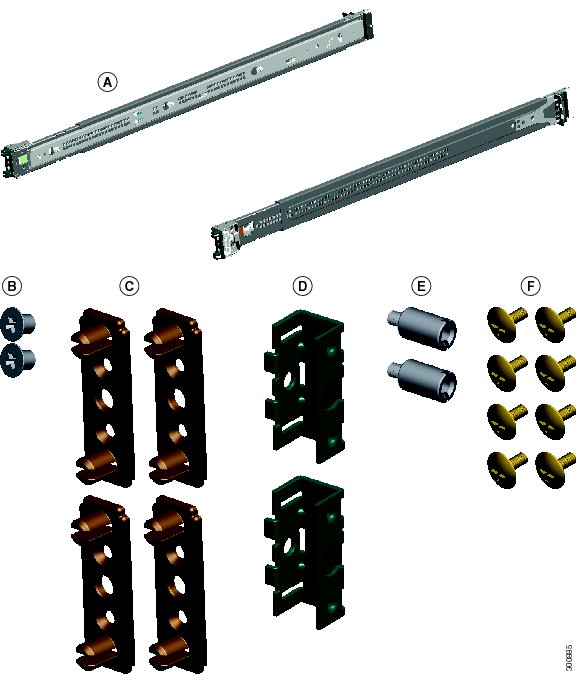
1 Verify the Box Contents
Remove the contents from the box and verify that it contains the following items for all rack types:
•
Slide Rails (x2) (preconfigured for square hole racks)
•
Phillips flat-head screws for Inner Slide (x2)
For round hole racks, you also need the following:
•
Round Hole Inserts (x4)
For threaded hole racks, you also need the following:
•
Threaded Hole Brackets (x2)
•
Threaded Hole Standoffs (x2)
•
Phillips pan-head screws for threaded hole racks (x8)
Tools Required:
•
Phillips screwdriver
•
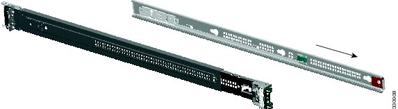
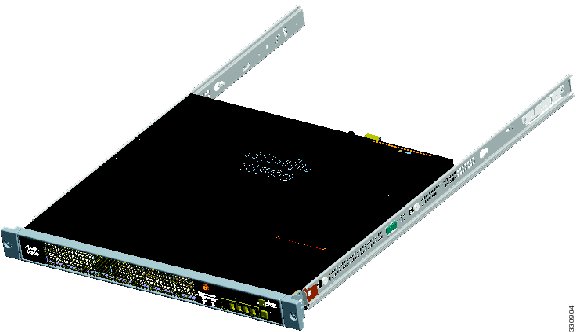
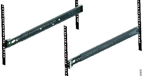
2 Disassemble the Slide Rail
Pull the inner slide rail from the outer slide rail.
Slide the plastic tab forward, and pull the inner slide rail to disconnect it from the outer slide rail.
Repeat the steps on this page for the other slide rail.
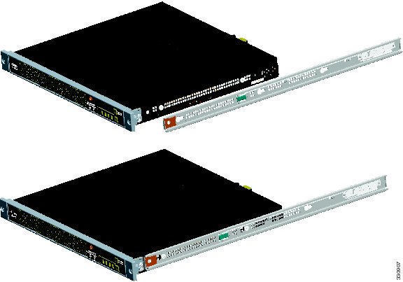
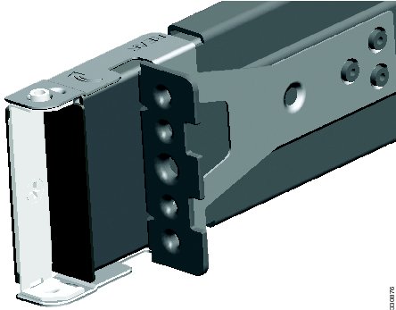
3 Attach Inner Rails to the Chassis
Align one of the inner slide rail key holes over the chassis shoulder screw on one side. Slide the inner slide rail forward so that the shoulder screw is securely in place.
Use a Phillips screwdriver to secure the inner slide rail with one Phillips flat-head screw
Secure the other inner slide rail to the chassis by repeating the previous steps on this page.
4 Verify the Rack Type
The slide rails are pre-assembled for square hole racks. See the following steps for the different rack types:
•
•
•
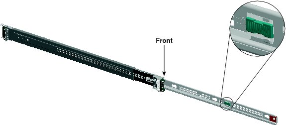
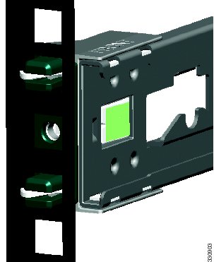
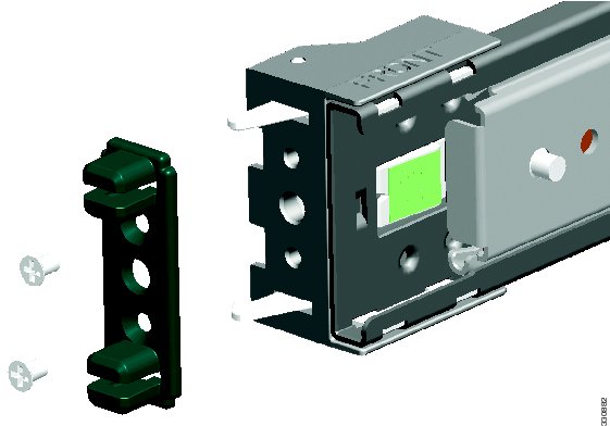
The following figure shows the slide rail with square hole rack inserts.
5 Round Hole Racks
Using a Phillips head screwdriver, remove the square insert from the rear of the rail. Keep the two Phillips head screws.
Remove the square insert from the front of the rail. Keep the two Phillips head screws.
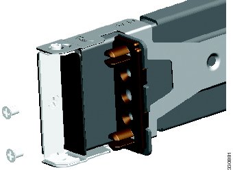
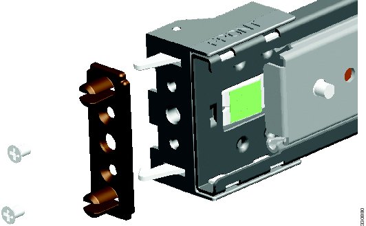
Align the round hole insert
Align the round hole insert
See "Attach the Outer Slide Rail to Round and Square Hole Racks" on page 8.
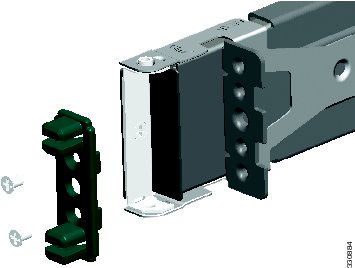
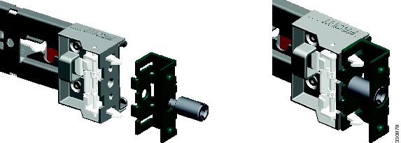
6 Threaded Hole Racks
Using a Phillips head screwdriver, remove the square hole insert from the rear of the rail.
Remove the square hole insert from the front of the rail.
Align the threaded hole bracket
No additional hardware is necessary for the rear adapter.
Repeat these steps page for the other slide rail. Go to the"Attach the Outer Slide Rail to Threaded Hole Racks" section.
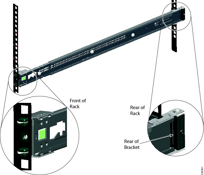
7 Attach the Outer Slide Rail to Round and Square Hole Racks
Align the front of one of the outer slide rails with the rack upright, push it forward, and click it into place. Align the rear of the outer slide rail with the rack upright, pull the release tab, push the slide rail toward the rack, release the tab, and click it into place.
Note
Secure the other outer slide rail to the rack by repeating the previous steps.
Go to the "Install the Chassis" section.
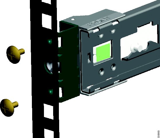
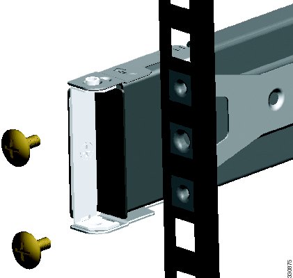
8 Attach the Outer Slide Rail to Threaded Hole Racks
Align the slide rail to the front rack post. Secure it with two of the included Phillips pan-head screws
Align the slide rail to the rear rack post. Secure it with two of the included Phillips pan-head screws
Align the other slide rail to the rack by repeating the previous steps on this page.
Go to the "Install the Chassis" section.
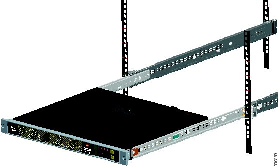
9 Install the Chassis
Align the inner slide rails to the outer slide rails. Install the inner slide rails into the outer slide rails until they lock into place.
Pull the side release tabs to unlock the inner slide rail, and push the chassis assembly into the rack.
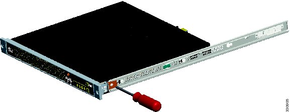
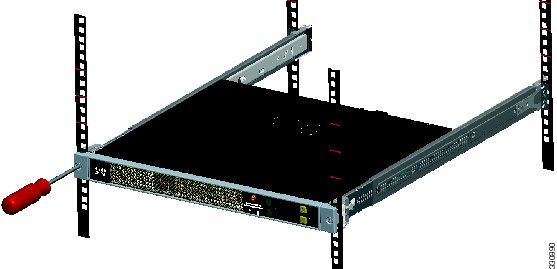
10 Secure the Chassis
Secure the chassis to the rack with the front captive screws.
Obtaining Documentation and Submitting a Service Request
For information on obtaining documentation, submitting a service request, and gathering additional information, see the monthly What's New in Cisco Product Documentation, which also lists all new and revised Cisco technical documentation, at:
http://www.cisco.com/en/US/docs/general/whatsnew/whatsnew.html
Subscribe to the What's New in Cisco Product Documentation as an RSS feed and set content to be delivered directly to your desktop using a reader application. The RSS feeds are a free service. Cisco currently supports RSS Version 2.0.
Cisco and the Cisco logo are trademarks or registered trademarks of Cisco and/or its affiliates in the U.S. and other countries. To view a list of Cisco trademarks, go to this URL: www.cisco.com/go/trademarks. Third-party trademarks mentioned are the property of their respective owners. The use of the word partner does not imply a partnership relationship between Cisco and any other company. (1110R)
© 2012 Cisco Systems, Inc. All rights reserved.