Feedback
Table Of Contents
Information about the ASA 5500-X
Cisco ASA 5500-X Series Chassis Overview
Internal and External USB Flash Drives
(Optional) External USB Drives
Online Insertion and Removal Support
Information about the ASA 5500-X
This chapter describes the Cisco ASA 5512-X, 5515-X, 5525-X, 5545-X, and 5555-X models. We recommend that you read this entire guide before beginning any of the procedures contained herein.
WarningOnly trained and qualified personnel should install, replace, or service this equipment. Statement 49
Caution
This chapter includes the following topics:
•
•
Cisco ASA 5500-X Series Chassis Overview
This guide supports the Cisco ASA 5500-X series models, which includes the ASA 5512-X, ASA 5515-X, ASA 5525-X, ASA 5545-X, and ASA 5555-X.
The Cisco ASA 5500-X series is a family of next-generation mid-range ASAs that are built on the same security platform as the rest of the ASA family. These next-generation ASAs provide more firewall throughput (4X firewall throughput), better scaling, more Ethernet ports (up to 14 GE ports), optional ASA CX SSP or ASA IPS SSP software modules, and redundant power supplies on the 5545-X and 5555-X models.
For More Information
•
•
http://www.cisco.com/en/US/products/hw/vpndevc/ps4077/products_documentation_roadmaps_list.html
•
http://www.cisco.com/en/US/docs/security/asacx/roadmap/asacxprsmroadmap.html
Internal and External USB Flash Drives
The Cisco ASA 5500-X series chassis have internal and (optional) external USB drives.
•
•
Internal USB Drive
An embedded USB (eUSB) device is used as the internal flash (disk0). See the "Hardware Specifications" section for the size shipped with each model.
(Optional) External USB Drives
The ASA 5500-X series supports external USB flash drives for data storage. The ASA 5500-X series use disk1 as the external USB flash drive identifier. When the ASA is powered on, an inserted USB flash drive is mounted to disk1 and available for you to use. Additionally, the file system commands that are available to disk0 are also available to disk1, including copy, format, delete, mkdir, pwd, cd, and so on. When you remove the USB flash drive, the system unmounts disk1, and disk1 becomes an invalid file system label that you can no longer access.
If you insert a USB drive with more than one partition, only the first partition is mounted.
Online Insertion and Removal Support
While the ASA back panel has two USB slots, only one is supported for Online Insertion and Removal (OIR), with priority given to the USB drive that was inserted first. For example, based on the time sequence, the first inserted USB flash drive is mounted to disk1, regardless of the slot in which you insert it. When you insert a second USB device, an error message displays on the console to notify you that an extra, unsupported USB flash drive exists. Removing either one of the USB devices does not change the priority that you just established. To change the priority you must safely remove the USB device and begin again to establish the desired priority.
FAT 32 File System
The ASA 5500-X series supports only FAT32 formatted file systems for the eUSB and external USB drives. If you insert an external USB drive that is not in FAT 32 format, the system mounting process fails, and you receive an error message. You can enter the format disk1: command to format the partition to FAT 32 and mount the partition to disk1 again; however, data might be lost.
Viewing Flash Memory
Check the amount of free flash memory on the ASA by doing the following:
•
•
Solid State Drives
You must install a Cisco Solid State Drive (SSDs) for use with the ASA CX SSP. Only Cisco SSDs are supported. Currently, the ASA CX SSP is the only process that can use the SSD for storage. You can install one SSD in the ASA 5512-X, ASA 5515-X, and ASA 5525-X. You can install two SSDs in a RAID 1 configuration in the ASA 5545-X and ASA 5555-X.
Note
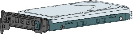
The SSD is hot-swappable. The SSD resides in a carrier, which you install into the drive bay. You can use the SSD with an AC or DC power supply.
Figure 1-1 shows the SSD in the carrier that it is shipped in.
Figure 1-1 SSD in Carrier
Management 0/0 Interface
You manage the ASA through the Management 0/0 interface. The Management 0/0 interface has the following characteristics:
•
•
•
•
•
The Management 0/0 interface is configured for management-only traffic, and you cannot disable management-only for the Management interface. Also, because the ASA 5500-X models do not allow subinterfaces on the Management interface, for per-context management, you must connect to a data interface for management.
The Management 0/0 interface is configured for ASDM access as part of the default factory configuration.
For More Information
For more information, see the "Rear Panel Ports" section.
Alarm LED
The ASA 5500-X series chassis perform autonomous environment monitoring to poll all external sensors and monitor operating conditions. In the event of damage to certain internal components or surpassed temperature thresholds, the system activates an alarm LED to notify you of a critical condition. For example, the alarm LED is activated by firmware in the event of various critical over-voltage and over-temperature conditions, as well as when the ASA has missing or unrecognized internal chip components. When the alarm LED lights, you can find details about the system condition from the system message that appears on the console or by entering the show environment or show controller pci command.
ASA 5500-X I/O Cards
The Cisco ASA 5500-X Series 6-port Gigabit Ethernet interface cards extend the I/O capabilities of the ASA 5525-X, ASA 5545-X, and ASA 5555-X models by providing additional Gigabit Ethernet ports.
The I/O cards provide the following benefits:
•
•
•
•
•
For More Information
For information about installing an I/O card in your ASA, see Chapter 4 "Maintenance and Upgrade Procedures for the ASA 5500-X."
SFP Modules
The ASA uses a field-replaceable SFP module to establish Gigabit Ethernet connections. Table 1-1 lists the supported SFP modules.
Table 1-1 Supported SFP Modules
1000BASE-LX/LH
Fiber-optic
GLC-LH-SM=
1000BASE-SX
Fiber-optic
GLC-SX-MM=
The 1000BASE-LX/LH and 1000BASE-SX SFP modules are used to establish fiber-optic connections. Use fiber-optic cables with LC connectors to connect to an SFP module. The SFP modules support 850 to 1550 nm nominal wavelengths. The cables must not exceed the required cable length for reliable communications. Table 1-2 lists the cable length requirements.
Use only Cisco certified SFP modules on the ASA. Each SFP module has an internal serial EEPROM that is encoded with security information. This encoding provides a way for Cisco to identify and validate that the SFP module meets the requirements for the ASA.
Note
ASA Chassis Panels
This section describes the front and rear ASA panels, and it includes the following topics:
Front Panel LEDs
This section describes the front panel LEDs for the Cisco ASA 5500-X series chassis.
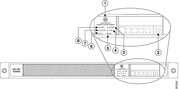
Figure 1-2 shows the front panel LEDs for the ASA 5512-X, ASA 5515-X, and ASA 5525-X models.
Figure 1-2 Front Panel LEDs for the Cisco ASA 5512-X, ASA 5515-X, and ASA 5525-X
Power button
A soft switch that turns the system on and off. Once depressed, the button stays in the "on" position:
•
•
For information about the power state, see the "Power Supply Considerations" section.
Hard disk release button
Releases the hard disk from the device.
Alarm
Indicates system operating status:
•
•
–
–
–
VPN
Indicates VPN tunnel status:
•
•
HD
Indicates Hard Disk Drive status:
•
•
•
PS
Indicates the power supply status
Active
Indicates the status of the failover pair:
•
•
Boot
Indicates power-up diagnostics:
•
•
•
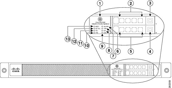
Figure 1-3 shows the front panel LEDs for the ASA 5545-X and ASA 5555-X models.
Figure 1-3 Front Panel LEDs for Cisco ASA 5545-X and ASA 5555-X
Power button
A soft switch that turns the system on and off. Once depressed, the button stays in the "on" position:
•
•
For information about the power state, see the "Power Supply Considerations" section.
Hard disk slot
Indicates the slot for hard disk 1.
Hard disk release button
Releases hard disk 1 from the device.
Hard disk release button
Releases hard disk 0 from the device.
Hard disk slot
Indicates the slot for hard disk 0.
Alarm
Indicates system operating status:
•
•
–
–
–
VPN
Indicates VPN tunnel status:
•
•
HD1
Indicates Hard Disk Drive 1 status:
•
•
•
HD0
Indicates Hard Disk Drive 0 status:
•
•
•
PS1
Indicates the status of the optional redundant power supply.
PS0
Indicates the status of the primary power supply that ships with the product.
Active
Indicates the status of the failover pair:
•
•
Boot
Indicates power-up diagnostics:
•
•
•
Rear Panel LEDs
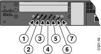
Figure 1-4 shows the rear panel LEDs for the ASA 5500-X series chassis.
Figure 1-4 Rear Panel LEDs for ASA 5500-X Series Chassis
Rear Panel Ports
Figure 1-5 shows the ports for the ASA 5512-X and ASA 5515-X models.
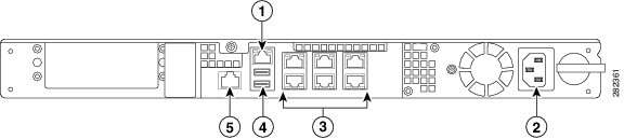
Figure 1-5 Rear Panel Ports for the ASA 5512-X and ASA 5515-X
Management 0/0 interface
Indicates the Gigabit Ethernet interface that is restricted to management use only. Connect with an RJ-45 cable.
(See the "Management 0/0 Interface" section.)
Power supply
Indicates the chassis power supply.
RJ-45 ports
Indicates the Gigabit Ethernet customer data interfaces.
The top row port numbers are (from left to right) 5, 3, 1.
The bottom row port numbers are (from left to right) 4, 2, 0.USB Ports
Indicates the two USB standard ports.
Console port
Indicates the console port that directly connects a computer to the ASA.
.
Figure 1-6 shows the ports for the ASA 5525-X.
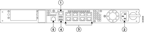
Figure 1-6 Rear Panel Ports for the ASA 5525-X
Management 0/0 interface
Indicates the Gigabit Ethernet interface that is restricted to management use only. Connect with an RJ-45 cable.
(See the "Management 0/0 Interface" section.)
Power supply
Indicates the chassis power supply.
RJ-45 ports
Indicates the Gigabit Ethernet customer data interfaces.
The top row port numbers are (from left to right) 7, 5, 3, 1.
The bottom row port numbers are (from left to right) 6, 4, 2, 0.USB Ports
Indicates the two USB standard ports.
Console port
Indicates the console port that directly connects a computer to the ASA.
Figure 1-7 shows the rear panel ports for the ASA 5545-X and ASA 5555-X.
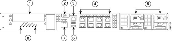
Figure 1-7 Rear Panel Ports for the ASA 5545-X and ASA 5555-X
I/O slot
Slot for the optional I/O Card. If you have a fiber I/O card, use SFP modules to connect (not included).
Thumbscrew
The screw that tightens and loosens the chassis cover.
Management 0/0 port
Indicates the Gigabit Ethernet interface that is restricted to management use only. Connect with an RJ-45 cable.
(See the "Management 0/0 Interface" section.)
RJ-45 ports
Indicates the Gigabit Ethernet customer data interfaces.
The top row port numbers are (from left to right) 7, 5, 3, 1.
The bottom row port numbers are (from left to right) 6, 4, 2, 0.Power supplies
Slots for the primary power supply that ships with the device and the optional redundant power supply.
USB ports
Indicates the two USB standard ports.
Console port
Indicates the console port that directly connects a computer to the ASA.
Rear panel LEDs
Shows the rear panel LEDs. (See the "Rear Panel LEDs for ASA 5500-X Series Chassis" for more information.)
Power Supply
The ASA 5512-X, ASA 5515-X, and ASA 5525-X ship with one fixed fan and one fixed power supply (AC or DC) installed. The ASA 5545-X and ASA 5555-X ship with one power supply (AC or DC) installed. You can add an additional power supply or you can order these appliances with two power supplies installed. Having two power supplies installed provides a redundant power option. This configuration ensures that if one power supply fails, the other power supply assumes the full load until the failed power supply is replaced. To maintain airflow, an empty bay must be covered or both bays must be populated with power supplies. If only one power supply is installed, make sure that it is installed in slot 0 (left slot) and that slot 1 (right slot) is covered with a slot cover. If only one power supply is installed, do not remove the power supply unless the appliance has been powered off. Removing the only operational power supply causes an immediate power loss.
Note
The power supplies each provide 400 W of output power and are used in a 1 + 1 redundant configuration. There is no input switch on the faceplate of the power supplies.
The Cisco ASA 5500-X series hardware operates on AC power and supports the ability to restore the previous power state of the system in the event that AC power is lost.
The power supply is switched from Standby to ON by way of a system chassis STANDBY/ON switch. Earlier ASAs (V01) require you to turn on the power with the power switch. Newer ASAs (V02) automatically turn on when you plug in the power cable. To determine your version, do one of the following:
•
•
For the V01 chassis, see the following limitations:
•
•
For the V02 chassis, the above limitations to not apply.
The power supply slot numbers are on the back of the chassis to the left side of each power supply. When facing the back of the chassis, power supply slot 0 (PS0) is to the left and power supply slot 1(PS1) is to the right. By default, the factory installs a single power supply in slot 0.
The ASA supports the following power supplies:
•
•
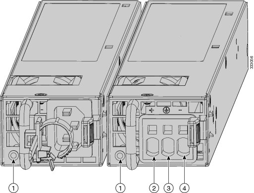
Figure 1-8 shows both the removable AC (on the left) and DC (on the right) power supplies for the ASA 5545-X and ASA 5555-X.
Figure 1-8 AC Power Supply and DC Power Supply
Power supply indicator
DC power supply positive connection
DC power supply neutral connection
DC power supply negative connection
Table 1-3 describes the power supply indicator. The function of the indicator is the same for both the AC and DC power supplies.
Hardware Specifications
Table 1-4 contains hardware specifications for the ASA 5500-X series models.
For More Information
•
http://www.cisco.com/en/US/prod/collateral/vpndevc/ps6032/ps6094/ps6120/data_sheet_c78-701253.html
•
http://www.cisco.com/en/US/prod/collateral/vpndevc/ps6032/ps6094/ps6120/data_sheet_c78-701808.html
Console Cable Pinouts
•
RJ-45 Console Cable
Cisco products use the following types of RJ-45 cables:
•
•
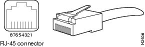
Figure 1-9 shows the RJ 45 cable.
Figure 1-9 RJ-45 Cable
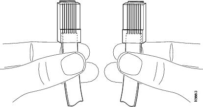
To identify the RJ-45 cable type, hold the two ends of the cable next to each other so that you can see the colored wires inside the ends, as shown in Figure 1-10.
Figure 1-10 RJ-45 Cable Identification
Examine the sequence of colored wires to determine the type of RJ-45 cable, as follows:
•
•
Table 1-5 lists the rolled (console) cable pinouts for RJ-45.
Table 1-5 RJ-45 Rolled (Console) Cable Pinouts
-
1
8
-
-
2
7
-
-
3
6
-
-
4
5
-
-
5
4
-
-
6
3
-
-
7
2
-
-
8
1
-
RJ-45 to DB-9 Console Adapter
Table 1-6 lists the cable pinouts for RJ-45 to DB-9 or DB-25.
Table 1-6 Cable Pinouts for RJ-45 to DB-9 or DB-25
RTS
1
7
DTR
2
4
TxD
3
3
GND
4
5
GND
5
5
RxD
6
2
DSR
7
6
CTS
8
8