Feedback Feedback
|
Table Of Contents
FIPS 140-2 Non-Proprietary Security Policy for the Cisco ASA 5500 Series Security Appliance
Security Appliance Validation Level
Physical Characteristics and Security Appliance Interfaces
Crypto Officer Guidance - System Initialization
Crypto Officer Guidance - System Configuration
Approved Cryptographic Algorithms
Obtaining Documentation and Submitting a Service Request
FIPS 140-2 Non-Proprietary Security Policy for the Cisco ASA 5500 Series Security Appliance
Introduction
This is a non-proprietary Cryptographic Module Security Policy for Cisco ASA 5510, ASA 5520, and ASA 5540 security appliances. This policy describes how the Cisco ASA 5500 series security appliances meet the requirements of FIPS 140-2. This document also includes instructions for configuring the security appliance in FIPS 140-2 mode. This policy was prepared as part of the Level 2 FIPS 140-2 validation for the Cisco ASA 5500 series security appliances.
Note
This document may be copied in its entirety and without modification. All copies must include the copyright notice and statements on the last page.
FIPS 140-2 (Federal Information Processing Standards Publication 140-2 — Security Requirements for Cryptographic Modules) details the U.S. Government requirements for cryptographic security appliances. More information about the FIPS 140-2 standard and validation program is available on the NIST website at http://csrc.nist.gov/cryptval/.
This document includes the following sections:
•
•
•
•
FIPS 140-2 Submission Package
The security policy document is one document in a complete FIPS 140-2 Submission Package. In addition to this document, the complete submission package contains:
•
•
•
With the exception of this non-proprietary security policy, the FIPS 140-2 validation documentation is proprietary to Cisco Systems, Inc. and is releasable only under appropriate non-disclosure agreements. For access to these documents, please contact Cisco Systems, Inc. See the "Obtaining Documentation and Submitting a Service Request" sectionfor more information.
Overview
The Cisco ASA 5500 series security appliance leverages Cisco's expertise in security and VPN solutions, and integrates the latest technologies from Cisco PIX 500 series security appliances, Cisco IPS 4200 Series Intrusion Prevention Systems, and Cisco VPN 3000 series concentrators.
The Cisco ASA 5500 series security appliances provide multiple integrated security and networking services, including:
•
•
•
•
•
•
The Cisco ASA 5500 series security appliance is a high-performance, multifunction security appliance family delivering converged firewall, IPS, network anti-virus and VPN services. As a key component of the Cisco Self-Defending Network, it provides proactive threat mitigation that stops attacks before they spread through the network, controls network activity and application traffic, and delivers flexible VPN connectivity while remaining cost-effective and easy-to-manage.
In a single platform, the Cisco ASA 5500 series security appliance offers the following:
•
•
•
Security Appliance Validation Level
Table 4 lists the level of validation for each area in the FIPS PUB 140-2.
Physical Characteristics and Security Appliance Interfaces
The Cisco ASA 5500 series security appliance family delivers enterprise-class security for medium business-to-enterprise networks in a modular, purpose-built appliance. Its versatile one-rack unit (1RU) design supports up to 8 10/100/1000 Gigabit Ethernet interfaces (on the ASA5520 and ASA5540) and 1 10/100 Fast Ethernet Management interface, making it an excellent choice for businesses requiring a cost-effective, resilient security solution with demilitarized zone (DMZ) support.
Each appliance is a multi-chip standalone security appliance, and the cryptographic boundary is defined as encompassing the "top," "front," "left," "right," and "bottom" surfaces of the case; all portions of the "backplane" of the case which are not designed to accommodate a removable interface or Cisco ASA 5500 series security appliance; and the inverse of the three-dimensional space within the case that would be occupied by an installed Cisco ASA 5500 series security appliance. The cryptographic boundary includes the connection apparatus between the Cisco ASA 5500 series security appliance and the motherboard/daughterboard that hosts the Cisco ASA 5500 series security appliance, but the boundary does not include the Cisco ASA 5500 series security appliance itself. In other words, the cryptographic boundary encompasses all hardware components within the case of the device except any installed modular Cisco ASA 5500 series security appliance.
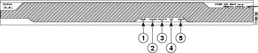
Figure 1 shows the ASA 5500 adaptive security appliance front panel LEDs.
Figure 1 ASA 5500 Adaptive Security Appliance Front Panel LEDs
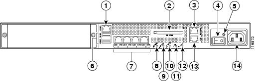
Figure 2 shows the ASA 5500 adaptive security appliance rear panel LEDs and ports.
Figure 2 ASA 5500 Adaptive Security Appliance Rear Panel LEDs and Ports (AC Power Supply Model Shown)
Management port1
USB 2.0 interfaces2
External CompactFlash slot
Network interfaces3
Serial Console port
Power indicator LED
Power switch
Status indicator LED
Power indicator LED
Active LED
1 The management 0/0 interface is a FastEthernet interface designed for management traffic only.
2 Not supported at this time.
3 GigabitEthernet interfaces, from right to left, GigabitEthernet 0/0, GigabitEthernet 0/1, GigabitEthernet 0/2, and GigabitEthernet 0/3.
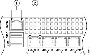
Figure 3 shows the adaptive security appliance rear panel LEDs.
Figure 3 ASA 5500 Adaptive Security Appliance Rear Panel Link and Speed Indicator LEDs
Table 2 lists the rear MGMT and Network LEDs.
Table 2 Link and Speed LEDs
Left side
Solid green
Physical link
Green flashing
Network activity
Right side
Not lit
10 Mbps
Green
100 Mbps
Amber
1000 Mbps
Note
Each security appliance provides a number of physical and logical interfaces to the device, and the physical interfaces provided by the security appliance are mapped to four FIPS 140-2 defined logical interfaces: data input, data output, control input, and status output.
The logical interfaces and their mapping are described in Table 3:
Table 3 Cisco ASA 5500 Series Security Appliance Physical Interface/Logical Interface Mapping
GigabitEthernet 0-3
Multi-Function Service Card (MFSC) Interface
MGMT Port
Compact Flash Type 1
Com 1 (Console Port)
Data Input Interface
GigabitEthernet 0-3
Multi-Function Service Card (MFSC) Interface
MGMT Port
Compact Flash Type 1
Com 1 (Console Port)
Data Output Interface
GigabitEthernet 0-3
Multiple Service Function (MFS) Interface
MGMT Port
Power Switch
Reset Switch
Com 1 (Console Port)
Control Input Interface
GigabitEthernet 0-3
Multi-Function Service Card (MFSC) Interface
MGMT Port
Ethernet LEDs
Power LED
Status LED
VPN LED
Active LED
CF Active LED
Com 1 (Console Port)
Status Output Interface
Power Plug
Power Interface
USB Port
Com 2 (Aux Port)1
Unused Interface
1 Physical interface not functional
Roles and Services
The security appliance can be accessed in one of the following ways:
•
•
•
•
As required by FIPS 140-2, there are two main roles in the security appliance that operators may assume: a Crypto Officer role and User role. The security appliance supports role-based authentication, and the respective services for each role are described in the "Crypto Officer Services" section, and the "User Services" section.
Crypto Officer Services
The Crypto Officer role is responsible for the configuration and maintenance of the security appliance and authenticates from the enable command (for local authentication) or the login command (for AAA authentication) from the user services. The Crypto Officer services consist of the following:
•
•
•
•
•
•
User Services
A user enters the system by accessing the console port with a terminal program or via IPSec protected Telnet or SSH session to a LAN port. The security appliance will prompt the user for their password. If the password is correct, the user is allowed entry to the executive program. The services available to the User role consist of the following:
•
•
•
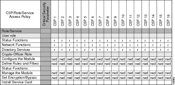
The services accessing the Critical Service Parameters (CSP)s, the type of access and which role accesses the CSPs are listed in Table 4.
Table 4 Cisco ASA 5500 Series Adaptive Security Appliance Validation Level by Section
Authentication Mechanisms
The security appliance supports either a password or digital certificates for authenticating IPSec users. To log on to the appliances for management purposes, an operator must connect to it through one of the management interfaces (Console Port, SSH, Telnet, or ASDM) and provide a password.
Table 5 describes the estimated strength of the authentication mechanism.
Cryptographic Key Management
The appliances use a variety of Critical Security Parameters during operation.
Table 6 lists the cryptographic keys used by the Cisco ASA 5500 series security appliance.
Self-Tests
The security appliances include an array of self-tests that are run during startup and periodically during operations to prevent any secure data from being released and to insure all components are functioning correctly.
Table 7 lists the ASA 5500 adaptive security appliance power-on self-tests.
The security appliances perform all power-on self-tests automatically at boot when FIPS mode is enabled. All power-on self-tests must be passed before a User/Crypto Officer can perform services. The power-on self-tests are performed after the cryptographic systems are initialized but prior to the initialization of the LANs; this prevents the security appliance from passing any data during a power-on self-test failure. In the unlikely event that a power-on self-test fails, an error message is displayed on the console followed by a security appliance reboot.
Table 8 lists the conditional self-tests that the ASA 5500 adaptive security appliance performs.
Mitigation of Other Attacks
The security appliances do not claim to mitigate any attacks in a FIPS-approved mode of operation.
Secure Operation
The Cisco ASA 5510, ASA 5520, and ASA 5540 adaptive security appliances meet FIPS 140-2 Level 2 requirements. This section describes how to place and keep the security appliances in a FIPS-approved mode of operation. Operating the security appliances without maintaining the following settings will remove the security appliances from the FIPS-approved mode of operation.
Crypto Officer Guidance - System Initialization
The security appliances were validated with adaptive security appliance software Version (file name: asa704-k8.bin). This is the only allowable image for FIPS-approved mode of operation.
The Crypto Officer must configure and enforce the following initialization steps:
Step 1
(config)# mode singleStep 2
(config)# no firewall transparentStep 3
(config)#crashinfo console disableStep 4
Step 5
(config)#fips enableStep 6
(config)#no service password-recoveryStep 7
(config)# config-register 0x1001Step 8
(config)#failover key hex <key>
Note
Note
- Before upgrading to V7.0.4, copy the configuration to a location off the device
- Use a text editor to modify the interface configuration
- Change the failover cables to the specified failover interface
- Upgrade to V7.0.4 and reload the modified configuration
Step 9
(config-terminal)#aaa authentication serial console LOCAL(config-terminal)#username <name> password <password>Step 10
(config-terminal)#aaa authentication ssh console LOCAL(config-terminal)#aaa authentication telnet console LOCALStep 11
(config-terminal)#aaa authentication enable console LOCALStep 12
(config-terminal)#username <name> password <password> privilege 15(config-terminal)#username <name> password <password> privilege 1Step 13
Step 14
Step 15
Note
Step 16
Crypto Officer Guidance - System Configuration
To operate in FIPS mode, the Crypto Officer must perform the following steps:
Step 1
Step 2
Note
Step 3
The following configuration settings are known to work when launching ASDM in a TLS-only environment with JRE 1.5.0_05:
a.
(config)# ssl server-version tlsv1-onlyb.
c.
Step 4
Step 5
Step 6
Step 7
Step 8
Step 9
Step 10
Step 11
Step 12
Approved Cryptographic Algorithms
The appliances support many different cryptographic algorithms; however, only FIPS approved algorithms may be used. Use the following cryptographic algorithms:
•
•
•
•
•
•
•
•
•
•
Note
Each cryptographic implementation adaptive security appliance software with on-board acceleration has achieved the certifications listed in Table 9.
Table 9 Algorithm Certificates
AES
320
105
3 DES
384
217
SHA-1
393
196
SHA-1 HMAC
124
125
RNG
143
144
RSA
105
106
DSA
150
151
Non-FIPS Approved Algorithms
The security appliances implement the following non-FIPS-approved cryptographic algorithms:
•
•
•
•
•
•
Tamper Evidence
All Critical Security Parameters are stored and protected within each appliance's tamper evident enclosure. The administrator is responsible for properly placing all tamper evident labels. The security labels recommended for FIPS 140-2 compliance are provided in the FIPS Kit (CVPNPIXASAFIPS/KIT). These security labels are very fragile and cannot be removed without clear signs of damage to the labels.
The Crypto Officer should inspect the tamper evident labels periodically to verify they are intact and the serial numbers on the applied tamper evident labels match the records in the security log.
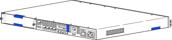
Apply the serialized tamper evident labels as follows (see Figure 4):
Figure 4 Cisco ASA 5500 Series Security Appliance Tamper Evident Label Placement
Step 1
Step 2
Step 3
Step 4
Step 5
The tamper evident seals are produced from a special thin gauge vinyl with self-adhesive backing. Any attempt to open the device will damage the tamper evident seals or the material of the security appliance cover. Because the tamper evident seals have non-repeated serial numbers, they may be inspected for damage and compared against the applied serial numbers to verify that the security appliance has not been tampered with. Tamper evident seals can also be inspected for signs of tampering, which include the following: curled corners, rips, and slices. The word "OPEN" may appear if the label was peeled back.
Related Documentation
This document deals only with operations and capabilities of the security appliance in the technical terms of a FIPS 140-2 cryptographic security appliance security policy. More information is available on the security appliance from the sources listed in this section and from the following source:
•
Obtaining Documentation and Submitting a Service Request
For information on obtaining documentation, submitting a service request, and gathering additional information, see the monthly What's New in Cisco Product Documentation, which also lists all new and revised Cisco technical documentation, at:
http://www.cisco.com/en/US/docs/general/whatsnew/whatsnew.html
Subscribe to the What's New in Cisco Product Documentation as a Really Simple Syndication (RSS) feed and set content to be delivered directly to your desktop using a reader application. The RSS feeds are a free service and Cisco currently supports RSS Version 2.0.
Definition List
AES—Advanced Encryption Standard
ASA—Adaptive Security Appliance
CMVP—Cryptographic Module Validation Program
CSP—Critical Security Parameter
DES—Data Encryption Standard
FIPS—Federal Information Processing Standard
HTTP—Hyper Text Transfer Protocol
KAT—Known Answer Test
LED—Light Emitting Diode
MAC—Message Authentication Code
NIST—National Institute of Standards and Technology
NVLAP—National Voluntary Laboratory Accreditation Program
RAM—Random Access Memory
RSA—Rivest Shamir and Adleman method for asymmetric encryption
SCEP—Simple Certificate Enrollment Protocol
security appliance—A security appliance may provide additional interfaces, feature acceleration or additional services. Security appliances may take a Circuit Board form factor SSM (for ASA appliances)
SHA—Secure Hash Algorithm
SSL—Secure Sockets Layer
SSM—Security Services Module
TLS—Transport Layer Security